09 Electronic Output
ALTERNATING CURRENT STIMULATION
This week, I wanted to produce the alternating current output for my final project. The output current will have to be modulated between 0-2mA over a sinusoid with varying frequencies. As a first step towards this, I consulted with TA Dave Preiss, and we found out that the D11C14A chip had a digital to analogue converter that could help us produce a alternating voltage output.

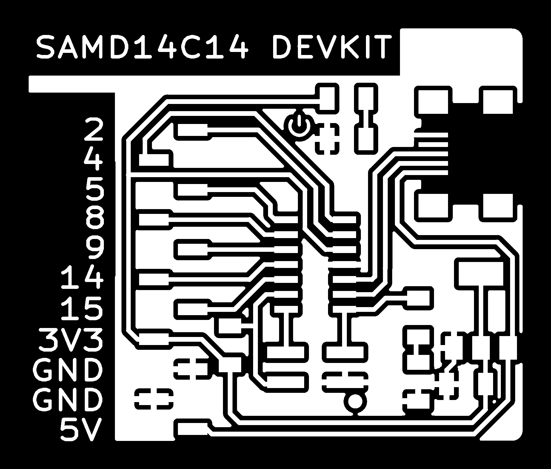

The best approach to ensure the output electronics from this week could be used in the final project was to build it as a breakout board, where I could later add the current regulating and safety components. To do this, I worked with TA Quentin Bolsee to use his D11C arduino devkit designs. The devkit has connectors for each pin of the SAMD11C14A microcontroller and an LED on one of the pins, allowing you to connect other boards or input or output devices to the microcontroller.
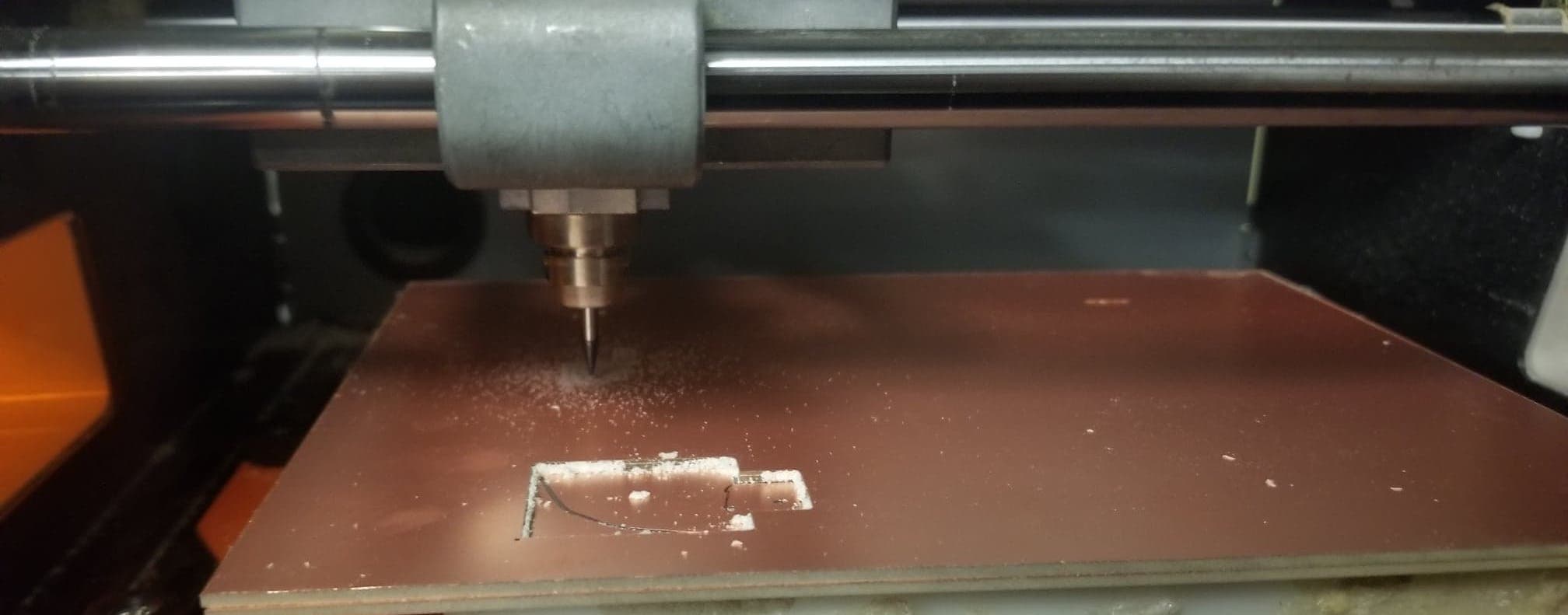
From Quentin's designs and using MODS, the traces were milled with an 1/64 endmill and 0.004 cut depth, and the outline with an 1/32 endmill and 0.05 cut depth on the Roland SRM-20. Before the milling process, I attached two copper plates to the SRM-20 with double-sided tape and zeroed the x, y and z-axis to the corner of the copper plates. To ensure that the endmill was touching the copper plate, I unscrewed the endmill and let it rest on the copper plate and then tightened it. I then calculated the milling path with 4 offsets and started the milling process.
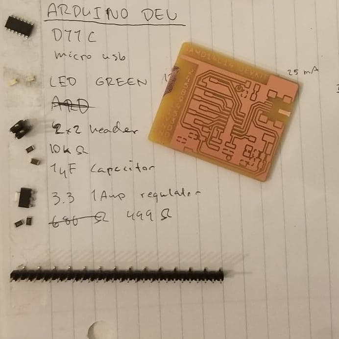
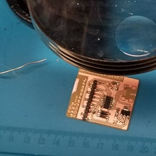
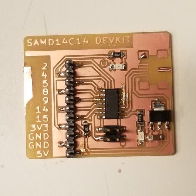
After the board was milled, I then started collecting the components for stuffing the board. The components included the SAMD11C14A microcontroller, micro-USB connector, 11x1 JTAG header, 2x2 JTAG header, 10k Ohm resistor, two 499 Ohm resistors, two green LED1206, a 5V to 3.3V Voltage regulator, and a 1µF capacitor. I then soldered the board. During the soldering process, I practiced using copper tape to remove solder and flux paste for more precise soldering. With the stuffed board, the bootloader was installed and I started to write code for it in the Arduino IDE.k
According to www.digilentic.com, a sinusoid wave function can be computed with the formula:

where "A" is the amplitude, "f" is the frequency of the sinusoid in Hz, "2π" are the radians in one cycle, "t" is the time in seconds, and "θ" is the angle. With this formula, I tried to do a simple implementation of a sinusoid function on the PCB through code in the microcontroller and visualize it with the Serial Plotter.
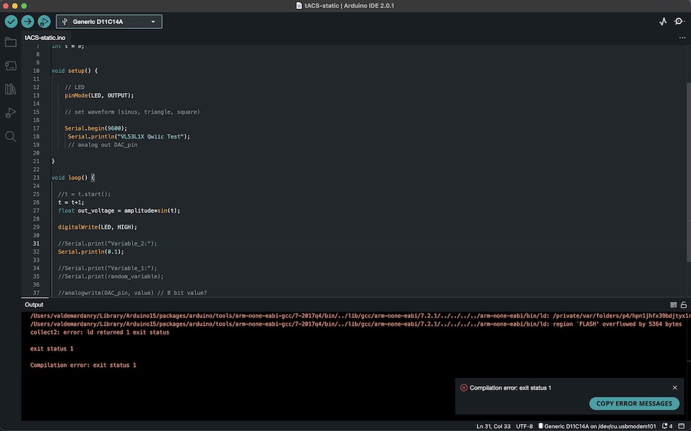
However, after writing some code to compute the simple sine function, I was not able to plot the results. Everytime I tried to print floating values the IDE would return the error message: "Flash overflowed by X bytes". After a lot of debugging, I found that the Serial Plotter would only work with integers - not floating values. With the help of TA Anthony, I came to learn that apparently the D11C14A microcontroller did not have enough memory to work with floats... This meant that I could not successfully finish the assignment. In a future version, I will build a devkit board that uses the SAMD21 microcontroller.