
Output Devices
Making data visible in interesting ways.
Making data visible in interesting ways.
Add an output device to a microcontroller board you've designed, and program it to do something.
Measure the power consumption of an output device.
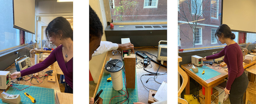
This week's group assignment was to measure the power consumption of an output device.
As a section (led by Selin, Rehana, and Caine!), we plugged a DC motor into a power bank and observed its behaviour in terms of speed.
We increased the voltage up to 25V per 3 units, and held for 10 seconds to observe the change in the accelaration of the speed. The change was almost constant.
This week, I set out to build an output device: something to make data visible in a manner easily perceptible to an understandable by humans.
I'm not yet 100% sure what my output device(s) will be for my final project, but I loved the screens Neil showed us in class. Because they seem so versatile, I figured I'd start there!
Enter: the OLED screen.
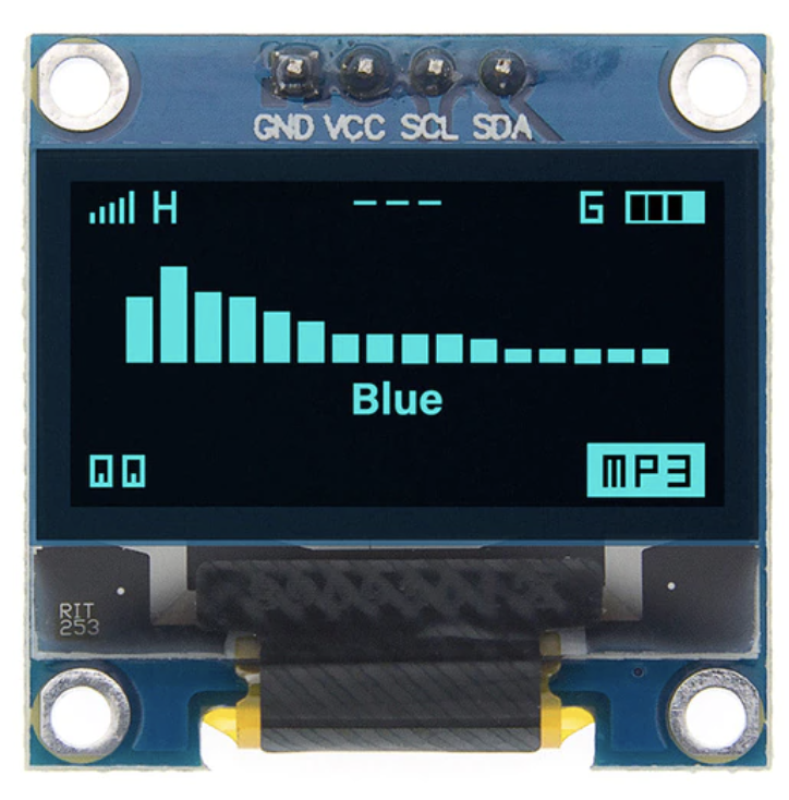
OLED stands for "organic light-emitting diode."
Compared to regular LEDs, OLEDs offer wider viewing angles and are better at handling darkness and lighting precision.
A tiny OLED, therefore, lets me display bitmap images, text, and animations.
Perhaps I'll use this to display a readerboard for competitive egg drop students, or display the data (or at least the results re: whether or not their "egg" broke) for my final project.
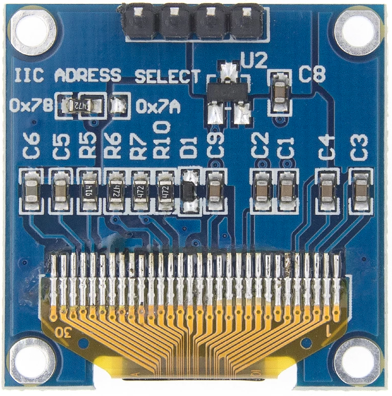
OLEDs, in theory, are pretty simple. There are only four wires:
The SCL and SDA are both I2C pins, which I knew were available on my SAMD21 devkit board. (These are the same ones I used for my accelerometer last week!).
Even so, I did have to double check the data sheet to remember which pins these were. I didn't want to get my wired crossed! (Pun intended... it's late, I'm sorry. Indulge me.) The were pins IO16 (data) and IO17 (clock) which translated to physical pins #17 (data) and #18 (clock).
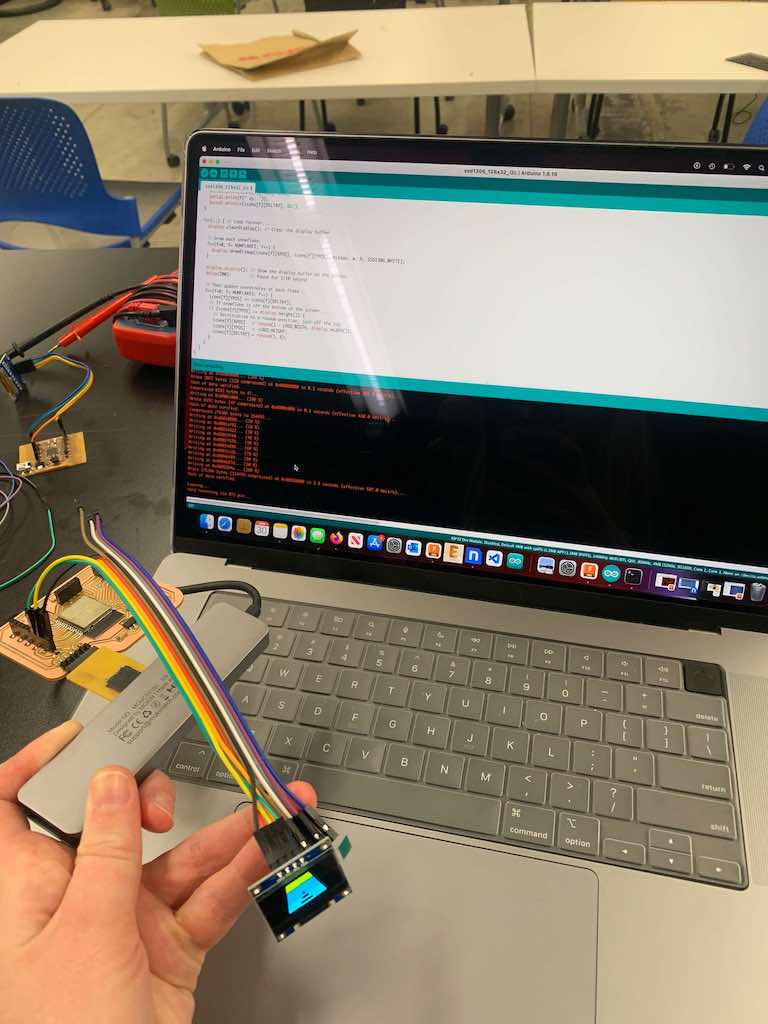
Because I'd intentionally designed my SAMD21 board as a devkit, linking most of its pins to headers, I was able to treat the OLED as its own breakout board.
In other words, I just used jumper cables to connect it to my SAMD21. Following common convention, I used black for ground and red for power. Then I arbitrarily assigned green to data and yellow to clock.
Note: some resources online suggest running these OLEDs off of 5 volts, but I had no problem running it off of 3.3.
Note: this tutorial from Random Nerd was supremely helpful for this step! I suggest giving it a read: https://randomnerdtutorials.com/guide-for-oled-display-with-arduino/
ADDING LIBRARIES
First things first: to add the relevant Arduino IDE libraries. These are 1) Adafruit_SSD1306 and 2) Adafruit_GFX.
Navigate to "manage libraries" and then type each one (SSD1306, followed by GFX in a separate search) into the search bar to install them.
Once both libraries are installed, navigate to "sketch" > "include libraries" and then select these two.
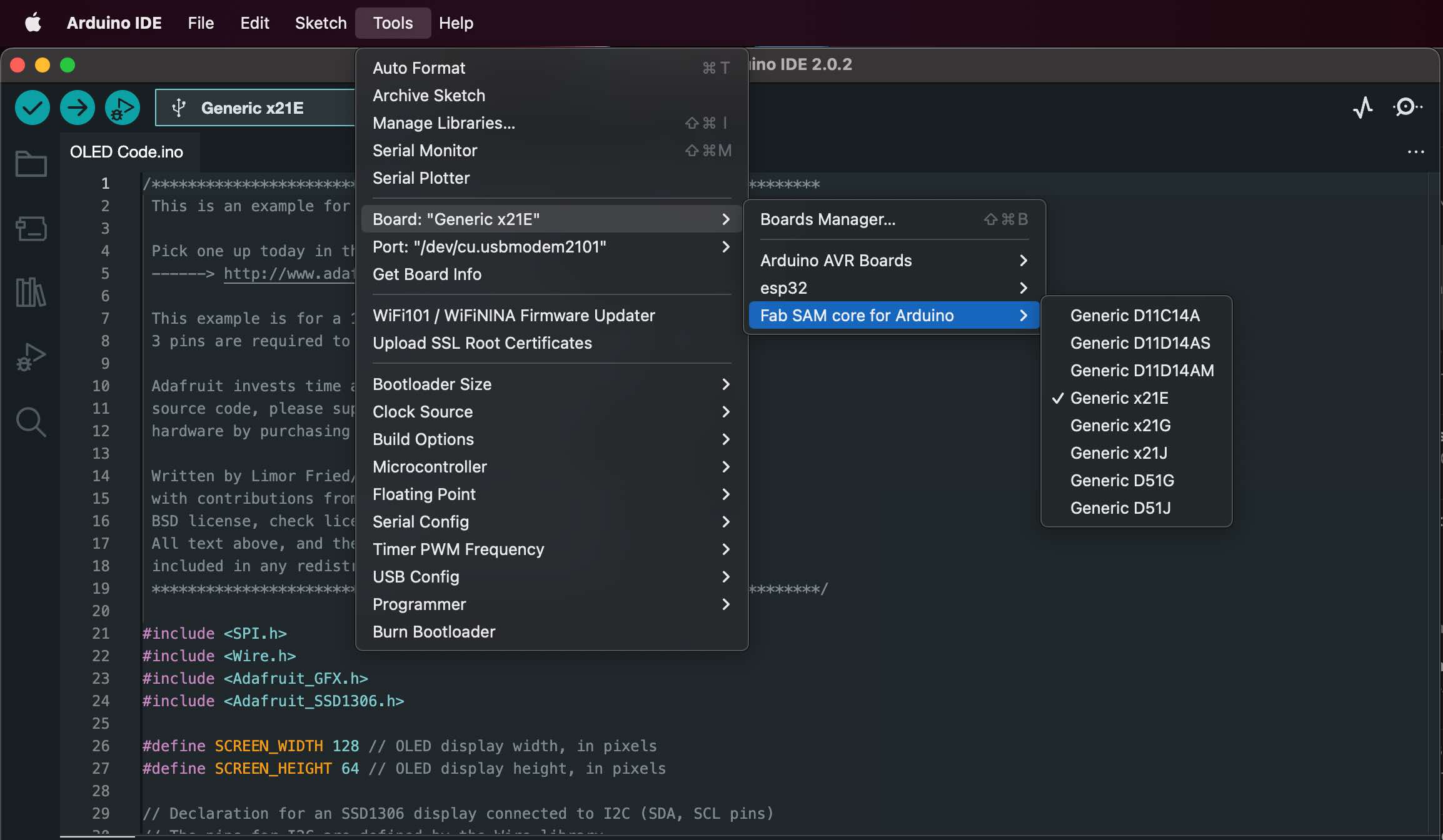
CREATING A SKETCH
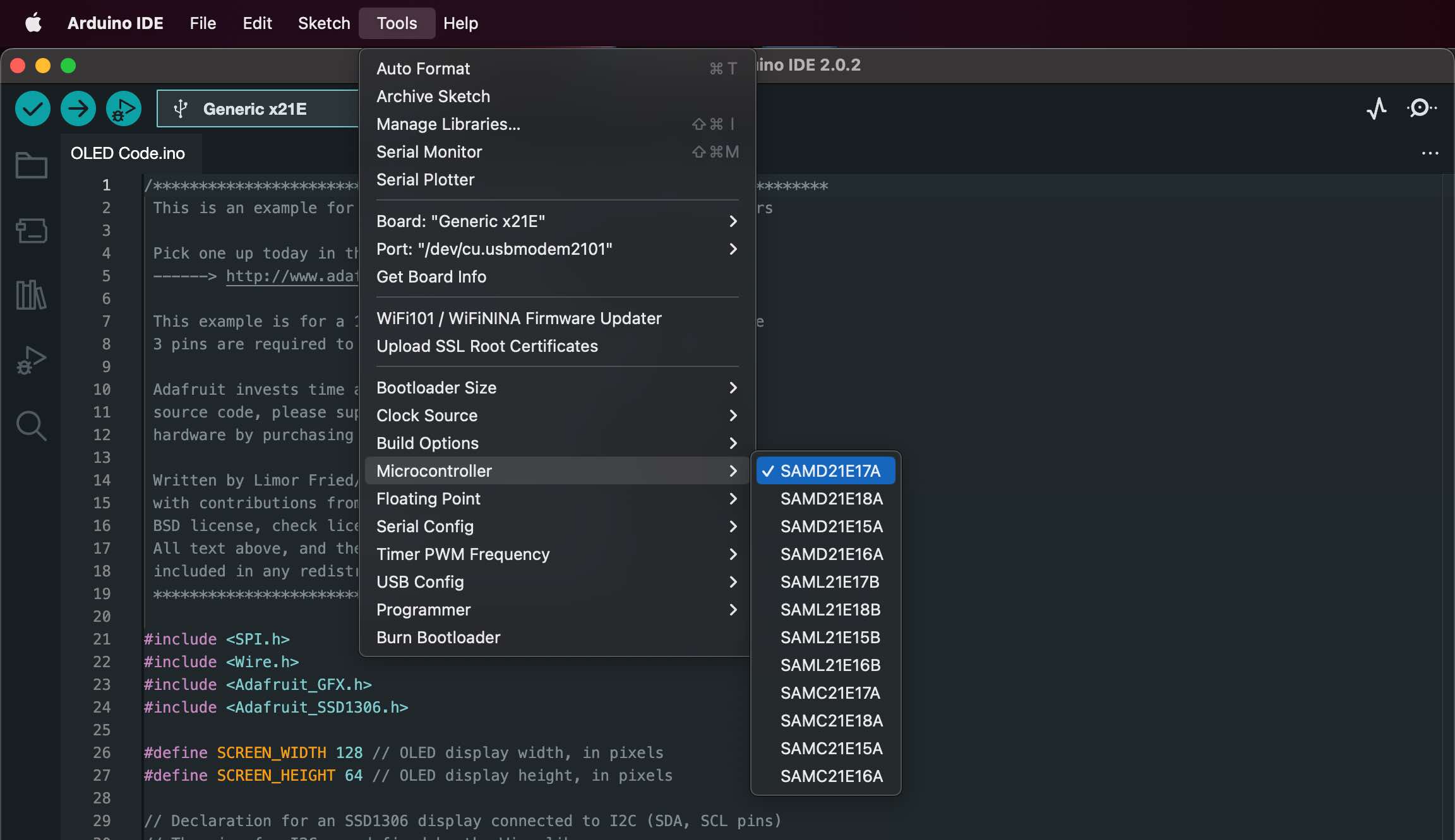
Make sure you have the correct port selected, and that Arduino is configured for your board.
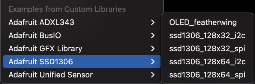
Then open the relevant example for your OLED. For the unit I was using, this can be found at File > Examples > Adafruit SSD1306 > ssd1306_128x64_i2c.
Since this unit doesn't have a RESET pin, the instructions in the example sketch tell us to enter "-1" for the reset variable. (Fortunately, this is the default in the sketch, so you'll only have to change it if you actually do have a reset pin.)
Then, follow the instructions to input your device's address.
Finally, flash the board. Now, the OLED should light up with a manufacturer-programmed animation!
....Except mine didn't.
CREATING A SKETCH
Make sure you have the correct port selected, and that Arduino is configured for your board.
Then open the relevant example for your OLED. For the unit I was using, this can be found at File > Examples > Adafruit SSD1306 > ssd1306_128x64_i2c.
Since this unit doesn't have a RESET pin, the instructions in the example sketch tell us to enter "-1" for the reset variable. (Fortunately, this is the default in the sketch, so you'll only have to change it if you actually do have a reset pin.)
Then, follow the instructions to input your device's address.
Finally, flash the board. Now, the OLED should light up with a manufacturer-programmed animation!
....Except mine didn't.
TROUBLESHOOTING
Although the board seemed to accept the programming (I didn't receive any errors), the OLED did nothing.
I knew my pins worked and that my connections were good, since my accelerometer breakout board still worked just fine using the same connection points. That meant I could rule out a hardware issue.
I finally decided the issue may have to do with the absence of a pullup resistor in my devkit board since the SAMD-21 doesn't have embedded pullup resistors like some other microcontroller and I remembered that I'd had to add one to my accelerometer breakout board previously. (Spoiler: this was not the problem.)
So, I switched tactics and tried hooking the OLED up to my ESP-32 board instead. (I have a writeup available for that board design in Week #11 if you need it).
When this didn't work either, I finally caved and asked TA Quentin for help. He confirmed I'd done everything right, so the OLED should be working... but it still wasn't.
We finally ran scanner code found here to confirm the OLED's i2c address: https://playground.arduino.cc/Main/I2cScanner/. The results were unexpected. For reasons unknown to me or Quentin, the address for our OLEDs in the lab was 0x3C instead of 0x3D, even though the instructions in the sketch indicate that it should be 3D for the size we were using. So if you can't get your OLED to work (it accepts the program without throwing an error, but nothing happens), try changing the address to 3D instead.
Once I made this change, I could get the OLED to work on both my SAMD21 and ESP32 boards!
CUSTOMIZING!
You can use this website to convert an image to bitmap: https://javl.github.io/image2cpp/
Or simply adjust the text that scrolls by!
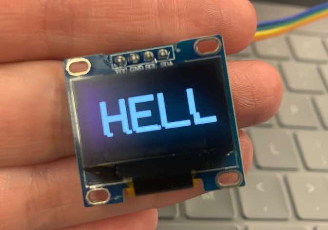
I happened to flash this one in the middle of "hello," which paused the scroll at a rather humorous point.
In all honesty, though, this week really wasn't that bad.
created with
Website Builder .