
Embedded Programming
Making a circuit board do something.
Making a circuit board do something.
Browse through the data sheet for your microcontroller
use your programmer to program your board to do something.
extra credit: try other programming languages and development environments
Compare the performance and development workflows for other architectures
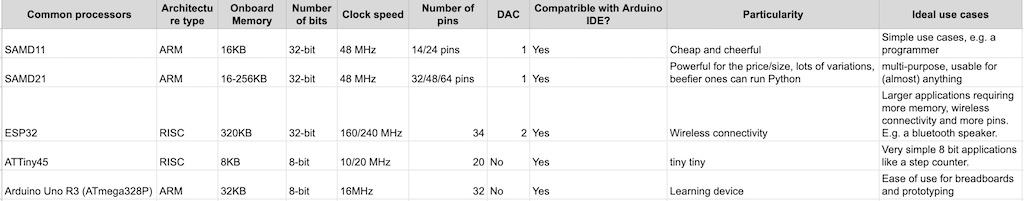
This week, led by Arthur, we compared the architectures of a number of different microcontoller chips including the SAMD11, SAMD21, ESP32, ATTiny45, and Arduino Uno.
I was much busier this week than usual while prepping for the grand opening of the manufacturing exhibit collection and STEM park and playground I've been working on for the last two years.
Knowing this, and since embedded programming is very new to me, I decided to keep things simple this week and program some behaviors on my existing board (the pumpkin-shaped one I designed and milled during week #5). I wanted to be able to use my button to turn my LED on and off. Simple enough, right?
Since the button and light aren’t in direct sequence in my microchip, I can’t achieve this functionality through hardware (essentially closing a circuit by pressing my switch). Instead, my button and light are both controlled by sepaarate digital pins. This means I have to use software to link them, essentially writing code to define and control their relative behaviors.
My chip is the ATSAMD11C. Here is its explanation and pinout:
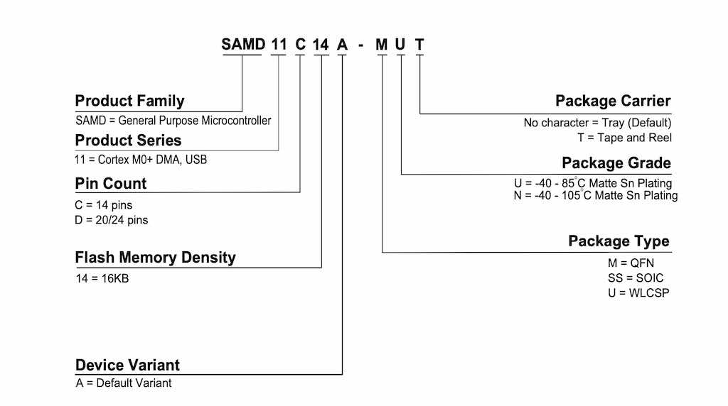
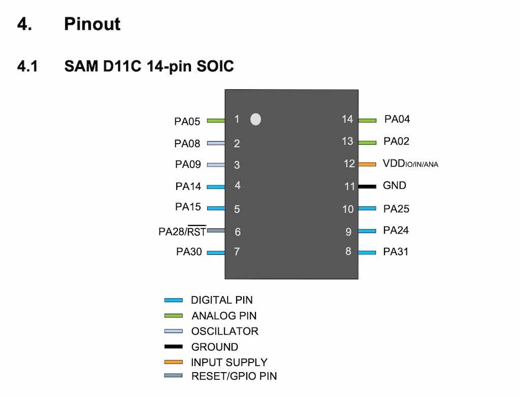
There are a total of 14 pins on my ATSAMD11C microcontoller, but only 10 of these can be used for input/output.
I first referenced the data sheet two weeks ago when determining which pins to use for my LED and button. In order for them to be independently programmable, both needed to be on separate digital pins. I chose pin #14 for my switch and pin #15 for my LED, which we can see on my board’s schematic.
But this week, I found myself wondering about the difference between analog and digital pins.
Analog Pins can recognize a range of voltages up to the limit set by the chip (5V in this case).
Digital Pins can only recognize two values (basically on and off): HIGH and LOW. These are geneally used to control various outputs, like lights (LEDs), buzzers, and motors but can also be used to ascertain the status of an input switch (essentially by checking whether it is on or off).
I also learned from TA Quentin that digital pins can be used similarly to analog pins (more or less). I had to look up how this works in order to better understand it. Arduino's guide helped me make sense of it: https://www.arduino.cc/en/Tutorial/Foundations/PWM
Essentially, we can use something called pulse width moderation (PWM), which uses a square wave (yay, oscilloscopes!). By varying the pulse width, we can simulate different voltage values that would be read from an analog pin. Interesting stuff!
Now that I had a better understanding of my board, I needed to determine how I would program it. I settled on Arduino IDE since it has excellent documentation and a reputation for being relatively user friendly.
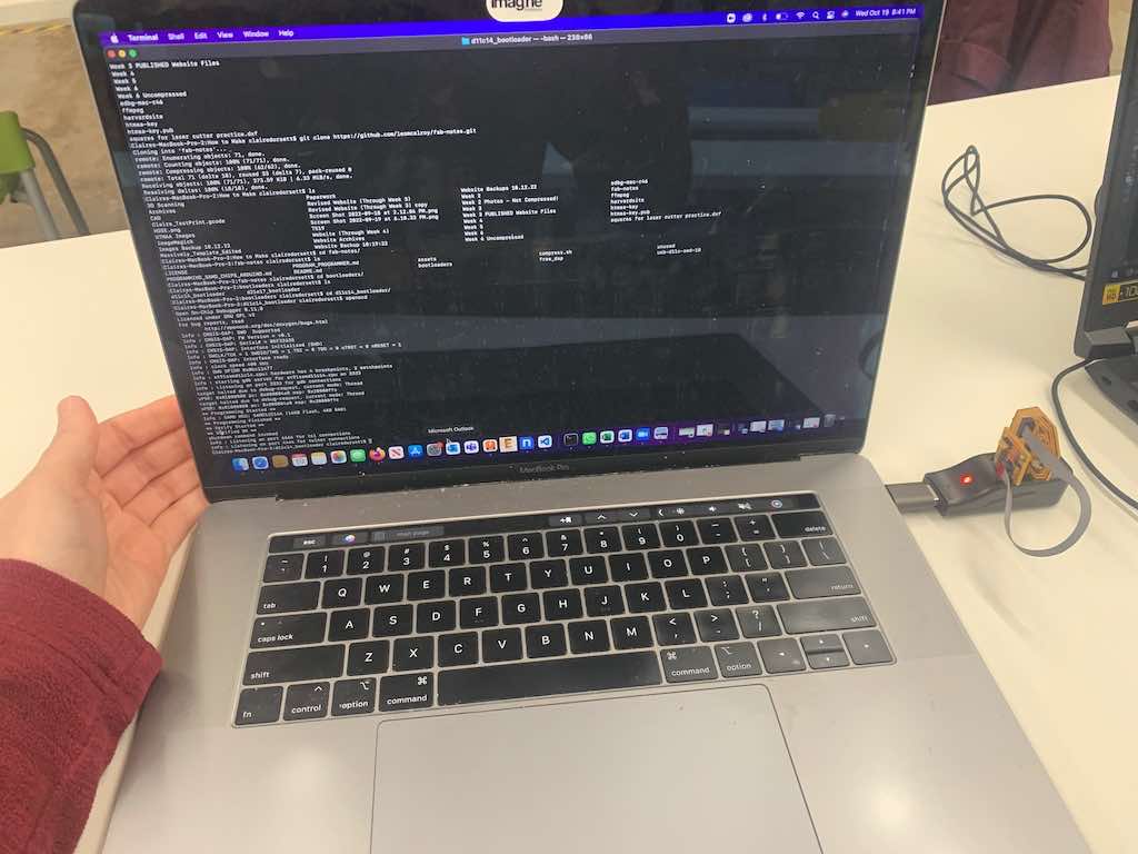
I followed TA Leo’s extremely useful guide here: in order to get this set up on my computer: https://github.com/leomcelroy/fab-notes/blob/main/PROGRAMMING_SAMD_CHIPS_ARDUINO.md
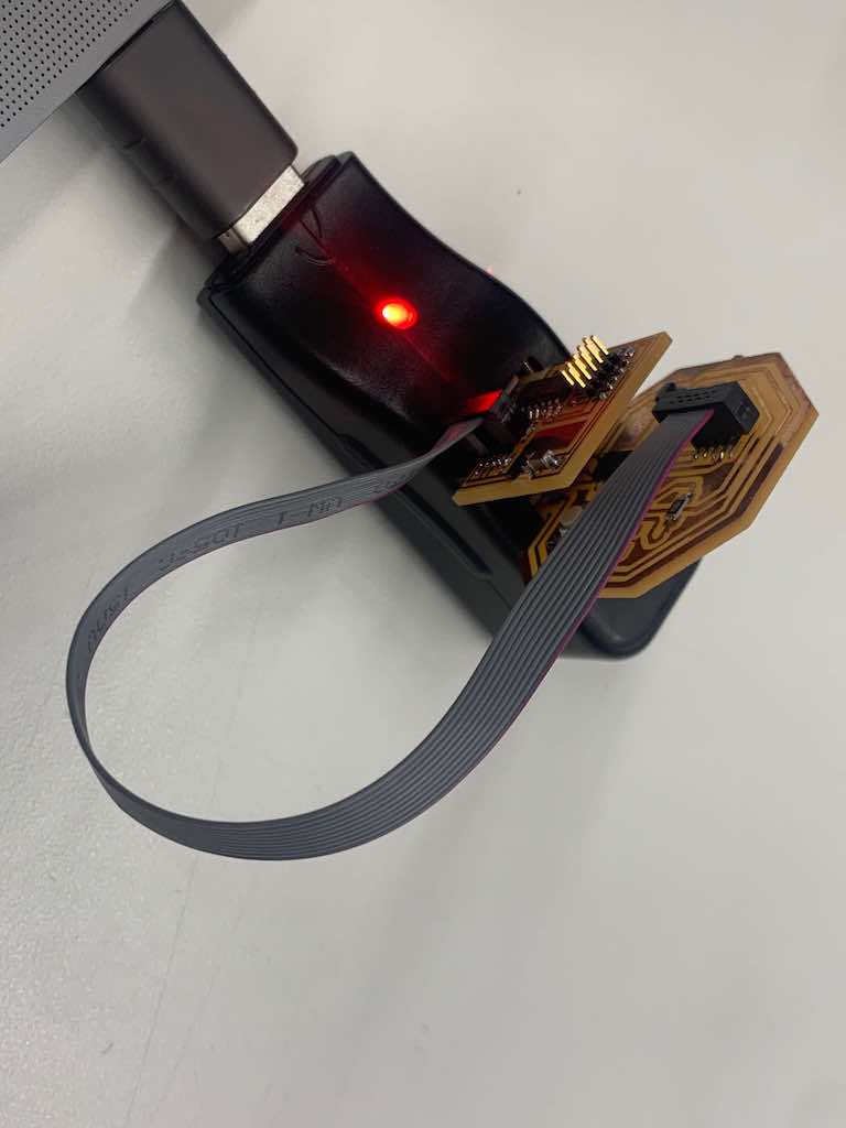
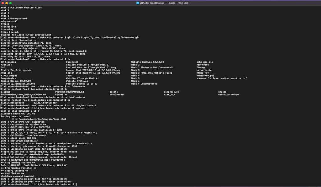
TA Quentin helped me set up the bootloader using my programmer. Then it was time to figure a basic blink program!
First, however, we had to figure out why my board was sometimes visible to the computer and sometimes not. Time for the debugging I’d heard so much about!
Its LED turned on, so I knew it was receiving power… but no data? We tried folded paper shims. We tried different computers and different adapters. I resoldered a few spots that Quentin said might be loose. No luck. Finally, Quentin advised me to cut one of the (perfectly good!!) traces on my board. He said that this was essentially butting up against the resistor from the other board and causing things not to work properly. I was definitely hesitant to cut a trace, but convinced myself I could add a 0ohm resistor to bridge the damage if need be and took the pluge. Despite my fears, this was successful!
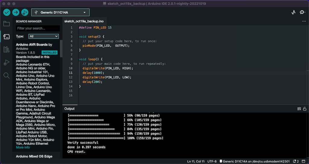
With my board now registering, it was time to revisit that blink program.
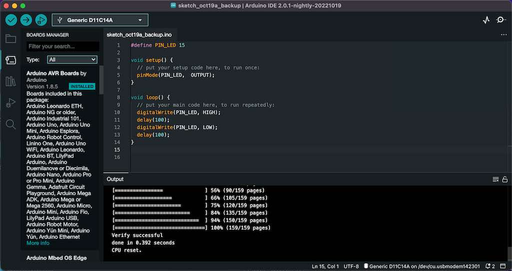
The code itself was a just a basic loop that instructed my LED to blink on and off. Quentin shared some wisdom that you should always “#define” things at a the beginning of the process to make things easier for you later on. This basically assigns nicknames to longer lines of code so that we can save some keystrokes. In Quentin’s words, this is “free,” meaning it doesn’t take up any memory.
To actually write the code, we used "digitalWrite" since this was on a digital pin. In the parentheses that followed, we put the relevant pin and our desired output from it. In this case, our PIN_LED is the input and our desired output is HIGH. Following that, in a new line, we set a delay in parentheses. This defines how many milliseconds the behavior will be sustained.
Since the goal was to make the light blink—not just stay illuminated—we also needed to program it to turn off for a period of time. This was also digitalWrite for PIN_LED, but this time the desired output was LOW. This also got a delay, so we could adjust the number of milliseconds the light would stay off before the loop repeated.
I started with a delay of 100 for both the high and low outputs. This meant my light should illuminate for 100 milliseconds, turn off for 100 milliseconds, and repeat perpetually.
By pressing the little right-facing arrow at the top of the Arduino IDE screen, I was able to upload this code to my board (or “flash” it).
My LED—which had turned on when the board was plugged in and receiving power—went dark for a moment while the code got pushed. Then my light started blinking! At regular intervals, just as programmed.
It was incredibly satisfying to know I had designed, milled, and now programmed this little rascal and it was successfully following code I wrote.
The next day, I decided to also play around with the delays in this program a bit just to get more comfortable with Arduino IDE before trying to link my button into the mix as well.
However, when I connected my board to my computer via the adapter, it once again refused to show up on my computer.
My LED turned on and blinked at regular intervals, telling me the board was successfully receiving power and still running yesterday’s programming—but that was it. No data.
Time for more debugging, and this time I was on my own. I knew this was a hardware issue, so set out to diagnose and doctor my board.
First, I triple checked my soldering and reflowed two spots just to be extra safe. No luck. Then, I added ~10 layers of clear tape to the back of the USB to act as a shim in case I was making strong enough contact for power but not data. No luck.
Just as I was contemplating remilling my board entirely, my classmate Treyden arrived at a the lab and asked to take a look. He was unsuccessful on my computer, so switched my adapter over to his to see if that might make a difference. It didn’t. Eventually, however, he decided to try plugging in his own board—and that one didn’t work either! This suggested that it was my USB adapter that was problematic rather than the boards themselves.
We switched to Treyden’s USB adapter, and his board showed up successfully. Then we tried mine… and it worked! So, lesson learned: hardware issues can very much extend to peripheral components in the system, like your adapter. (I ordered a new one…)
With my board now registering on the Arduino IDE, I was able to play around with the delay values. With my HIGH (on) delay at 1000 and my LOW (off) delay at 200, I could make my light illuminate for a nice long moment before flickering off and back on quite quickly.
Next, I set out to write a program that would allow me to control my board’s LED using the button. That meant that the button would be my input, and the LED would be my output.
In other words, I needed to read the voltage coming into my button to determine when it was pressed, and then output voltage to my LED to turn it on.
Remembering Quentin’s advice re: “defining is free,” I #defined both pins: LED_PIN = 15, and LED_BUTTON = 14.
Then, in setup(), I used pinMode() to define my input and output. (Interesting side note: I learned that C uses something called “camel case” meaning everything is all strung together and lower case except the first letter of a new word. That capital letter resembles a camel’s hump! There is also “snake case” that uses underscores to tie words together. Also new to me.)
At this point, I wasn’t sure what was next. I did some googling, got frustrated, checked previous HTMAA sites, and eventually stumbled across HTMAA 2021 alum Alex Ellison’s page: https://fab.cba.mit.edu/classes/863.21/EECS/people/alexellison/weeks/week7.html
This was exactly what I needed!
Reading through Alex’s documentation, I learned that to make my button function, I would have to set the buttonState to 0. I also realized that I needed to turn on the pull-up resistor by specifying INPUT_PULLUP. Thanks, Alex! Using these insights, I finished entering the code.
And then, the moment of truth: flashing my board.
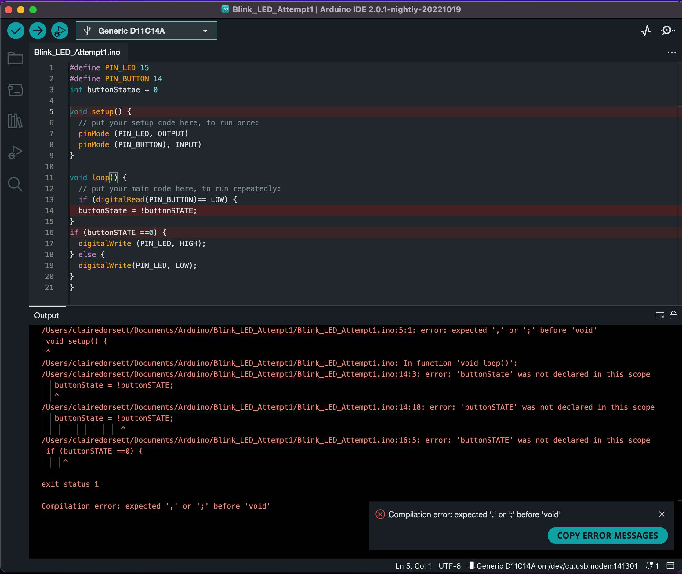
The verdict? A slew of errors.
Definitely overwhelming at first, but I gradually began working through what went wrong by tweaking things one by one and rerunning the program. Sometimes I got more errors—in which case I quickly undid whatever I’d just changed—but sometimes I got fewer errors. Baby steps!
I did like how helpful Arduino IDE was during debugging in terms of flagging which lines had errors and providing basic descriptions about what they might be. This wasn’t perfect—it didn’t tell me when I’d spelled something wrong or misplaced a capital letter—but it did at least point me to the general issue (and tell me whether I was missing punctuation).
Here are some of the mistakes I made:
-Misspelling “buttonState” as “buttonStatae” in my first introduction, which caused cascading errors later every time I referenced it.
-Forgetting a whole bunch of semicolons
-Messing up camelCase a bunch of times (e.g. buttonSTATE instead of buttonState)
-Skipping spaces between things
-Misplacing curly braces
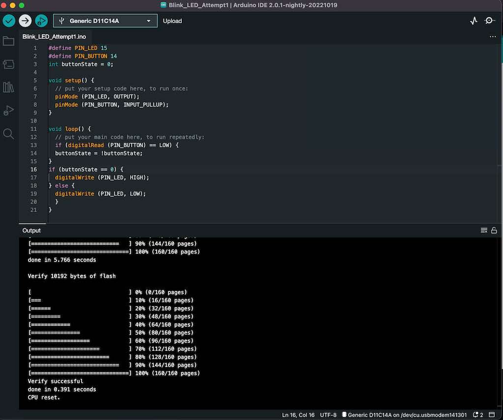
Eventually, by finding and fixing them one or two at a time, I corrected all of my errors. After many failed attempts, flashing the code to my board actually worked!
DEBOUNCING
My board did (sometimes? usually?) turn on the LED when the button was pressed—but not quite consistently. It seemed to work sometimes and not others. While this was better than nothing, it was far from ideal.
Google—and Alex’s page—suggested that a this was a debouncing issue, so I looked up debouncing on Arduino's site: https://www.arduino.cc/en/Tutorial/BuiltInExamples/Debounce
What does that mean? Arduino offers this useful definition and guidance: “Without debouncing, pressing the button once may cause unpredictable results. This sketch uses the millis() function to keep track of the time passed since the button was pressed.”
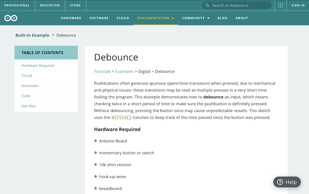
By introducing a millis() function, I could force the board to check twice within a short period of time to confirm that the button was actually triggered. This would theoretically eliminate the issue.
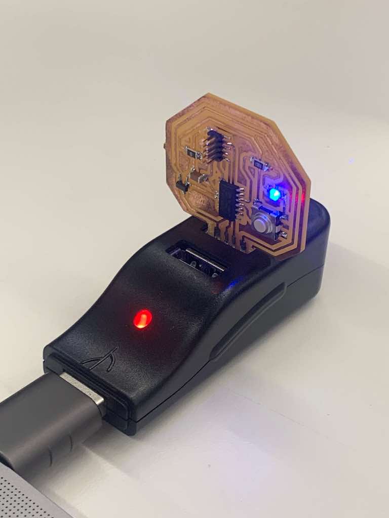
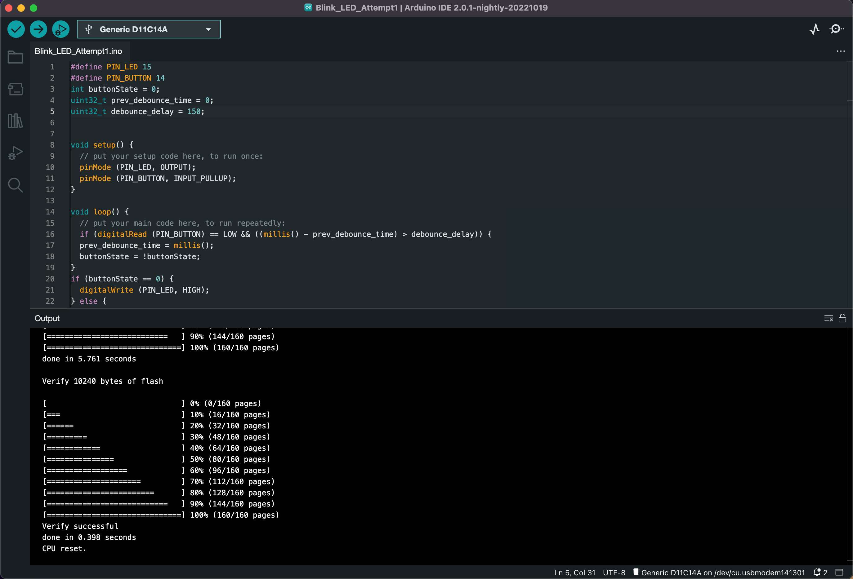
Following the Arduino guidance and Alex’s steps from his own encounter with this issue, I reworked my code. Miraculously, I had no error messages this time when I flashed it to my board—and it worked! Now when I push the button, my LED reliably turns on and off.
Success!
My first embedded program.
I’m excited to learn more about this as we work on input and output devices over the course of the coming weeks.
If I move forward with the mechanical mirror final project, I will need to design a new board capable of handling embedded programming for a camera and a series of servo motors to control the physical “pixels.” If I move forward with the egg drop, I will need to design one that can handle an accelerometer as well as a bluetooth device to send data back to the dashboard. Both will require a much firmer grasp of embedded programming!
created with
Website Builder .