Electronics Production
Milling, soldering, "stuffing," and programming circuit boards.
Milling, soldering, "stuffing," and programming circuit boards.
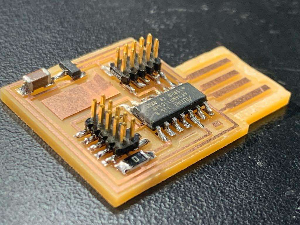
Make an in-circuit programmer that includes a microcontroller. Mill and stuff the board. Program it. Test it to verify it works.
Characterize the design rules for your in-house PCB production process (PCB = printed circuit board).
My class came together as a group on Saturday afternoon to complete the group assignment: characterizing the design rules for our machine.
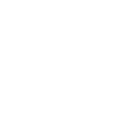
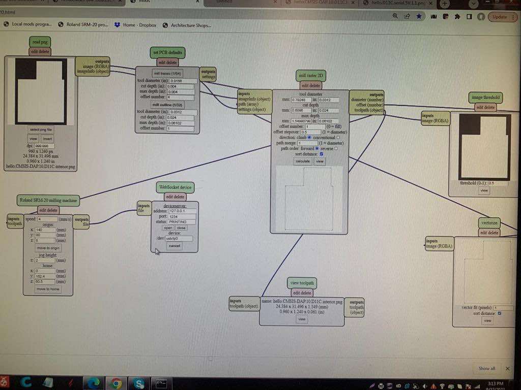
This meant running a set of specific trace and outline files that Neil provided in order to see how different settings on the mill (depth and otherwise) fared.
The file was set up to showcase how finely the tracing bit (1/64) was able to mill tiny lines in the patterning.
One we got the files uploaded to mods, this was a quick process. I love the different tests for different machines. It's so useful to see what they can do!
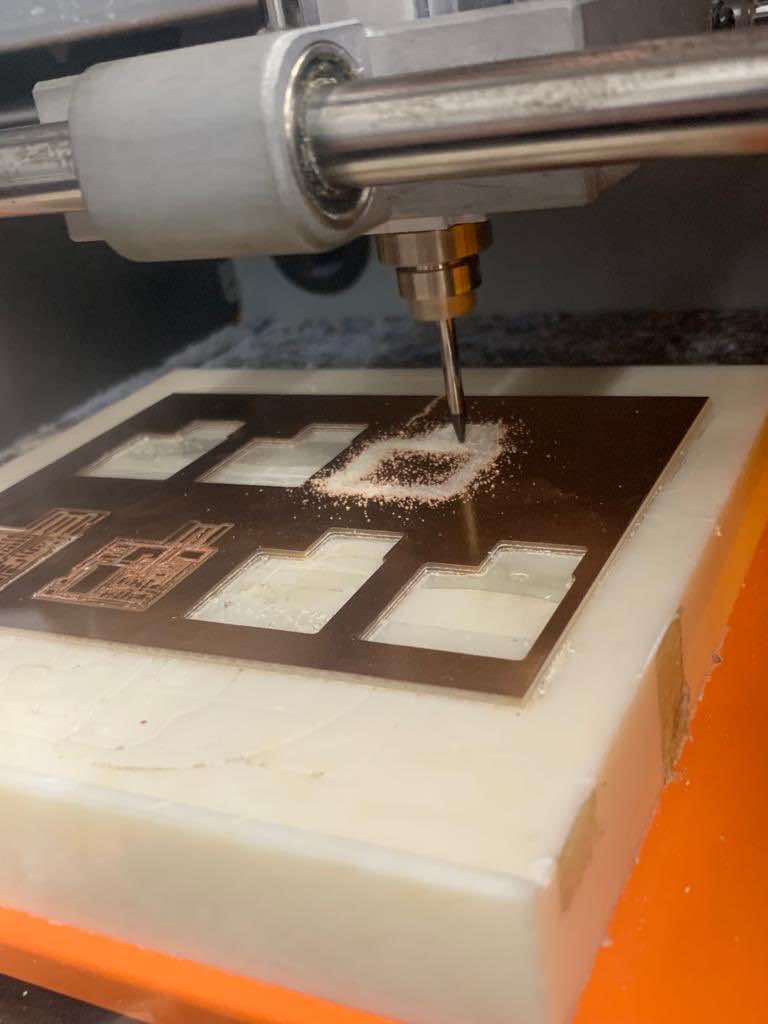
We started this week by learning how to use the Roland milling machine to mill circuit boards from scratch. This time, we used trace and outline files provided by the teaching team, but in a few weeks we'll have to design our own.
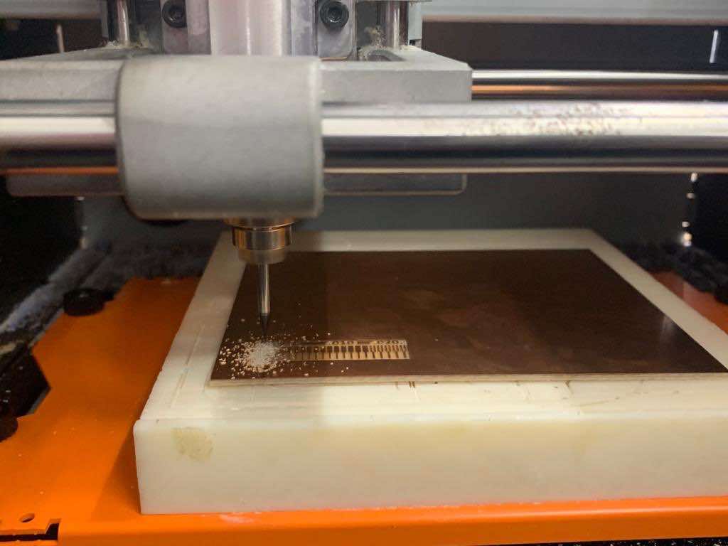
The software application used to control our mill is called "mods." Mods was created by Neil and his team to be modular so that different functionalities and pathways can be combined into workflows to run many (perhaps all?) of the Fab Lab's machines. While it doesn't have the friendliest user interface for beginners—various settings and buttons aren't always immediately obvious—mods is a very powerful and versatile tool.
Tip: For mods to work, its server must be running in the background.
Once mods is up and running, load a .png file for either the board's traces (the shallow pattern in the copper) or its outline. In the "Set PCB Results" box, make sure to choose the correct setting for the file and endmill you've selected. This will be either "mill traces" or "mill outline." The setting you've selected will appear in bold. Then click the "calculate" button under the "Mill Raster 2D" box in order to feed the file through the rest of the workflow.
With your software set up, now it's time to prepare the Roland itself. First, select a copper-coated sheet. This is what you'll be milling your board from. Apply several strips of double-sided tape to the backside of the sheet and affix it firmly to the sacrificial mill bed. Press down hard! If your tape is loose, the sheet may move and ruin your job. This can cause the traces not to translate all the way through the copper, or result in imperfect lines.
Now it's time to select and mount your endmill. Endmills are like drillbits, but designed to mill laterally as well as plunge. We're working with two endmills to make our circuit boards: 1/64 (smaller/thinner) and 1/32 (larger/thicker). The smaller endmill will be used for the traces, while the larger will be used for the outline—essentially to cut our board out once it's done. We're going to start with traces, meaning we need the smaller drillbit (1/64) first.
Tip: Order of operations matters here. Just like on the laser cutter, you want to tackle any surface-level design elements first, before cutting. (Once you cut, the substrate can move more freely. This introduces opportunities for error when the surface-level rastering/engraving occurs, expecially on a mill where there's friction occurring between the endmill and substrate.)
With the mill in its "home" position, use an allen key to loosen the set screw in the collet (the sleeve that holds the endmills in place). Insert the appropriate endmill for your job into the collet so that only a small bit of it is sticking out. Holding this in place, re-tighten the endmill with the allen key. But don't crank on it and break the endmill! Snug is fine. Make sure to close the mill's lid/shield when you're done since it won't move when this is opn.
Now you need to calibrate your origin. Remember: x-axis = left and right, y-axis = forward and backward, and z-axis = up and down.
For the x- and y-axes, trial and error is honestly the easiest way to get your bearings. For the z-axis, keep your value low (~10 or lower) so you don't accidentally lower the endmill so far that it breaks off against the side of the sacrificial bed as it moves. If you don't know where else to start, try 20 and 20 for the x- and y-axes and go from there. Then, click the "move to origin" button.
Tip: The "origin" marks the spot where the job will begin. This is always in the lower lefthand corner.
The mill will begin to spin, and then move to the origin you've just programmed. If it isn't lined up quite the way you want it—perhaps it's not even above the board at all!—you'll need to adjust your axis values and click "move to origin" again. Rinse and repeat until you have successfully stationed the endmill in an appropriate spot to begin your job. Remember to be efficient with your material! Try to position things so you can get the maximum number of pieces from your substrate.
Once you have an appropriate origin programmed and your endmill is in place above it, it's time to drop the endmill down to your substrate. Do this by loosening the set screw and—gently!—dropping the endmill so that its tip is in contact with the copper plate. Then re-tighten the set screw.
Now you're ready to mill!
Problems to be prepared for: Don't You'll probably make the same mistake I did a few times during this step: if you open the mill's door too soon after it moves (from "home" to "origin," for example), it'll throw a fault and you will have to reset the machine and start over. Unplug the machine, plug it back in again, turn it back on, and try to be more patient next time.
You'll probably have to hit the "calculate" button again to feed the file back through the workflow software. Then click "send file to device."
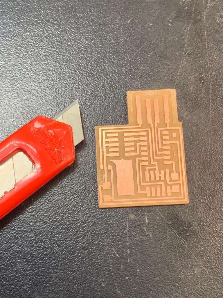
The tracing process will take a while. When it's done, use a vacuum to suck up the debris left behind. Your board should now have clear paths milled through just the upper layer of copper.
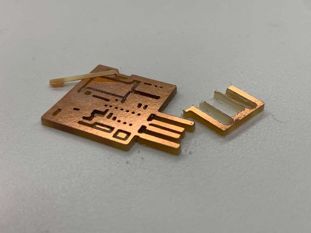
Problems to be prepared for: If your board doesn't come out quite perfect, your substrate probably wasn't adhered well enough to the bed. Unfortunately, you'll have to start over (though this still makes a good practice board for soldering, so it's still worth cutting out first!).
Dont do what I did: After the last person finished cutting out their board, I forgot to switch the mill settings back to "trace" from "outline." Because of the way the debris collects on top of the board, I couldn't see my error until it was too late and the job had already finished... so I essentially cut out all of the tiny details that were supposed to be traced at surface level, since the endmill was plunging too deep. I felt pretty silly after that one, but at least it's a mistake I'll never make again.
Don't touch your origin settings after your board has been milled. You still need to cut it out!
First, swap out the "traces" file for your "outline" file. Be sure to click over to the appropriate "mill outline" settings, and then press "calculate" to feed the file through the workflow.
Next, repeat the process outlined in Step #2 to prepare your milling machine. This time, use the larger of your two endmills (1/32 instead of 1/64). You'll have to put the right endmill in, press "move to origin," and then drop the endmill down until it touches your substrate again before milling.
When this is all done, click "send file to device" to mill your outline and cut out your board!
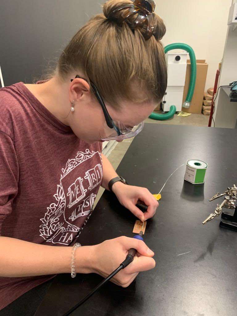
Once your board is traced and cut, it's time to solder. I recommend practicing on a few scrap boards first to get the hang of it.
You're first going to turn on your vent hoses and soldering iron. Wet the sponge for your soldering iron with some water. You'll use this—as well as brass wool—to clean the tip of your iron as you go.
Next, coat the copper pads you'll be soldering onto with a thin layer of flux. (This looks like a feltip marker that deposits flux instead of ink.) Prepare your components nearby, and ready some soldering wire.
Tip: thinner wire makes this process much easier when you're working with tiny components. I also found the lead wire easier to work with than the lead-free for components this small, as it flowed a bit more easily.
When you're ready to start soldering, you'll hold the iron's hot tip to the copper pad you intend to solder onto for a few moments. Leaving this there, you're then supposed use your other hand to introduce the soldering wire, guiding its to meet the tip of the iron. It should only take a moment before this begins to melt and flow; as soon as it does, take both away. However, I personally found it easier to introduce the iron and wire to the copper pad at the same time.
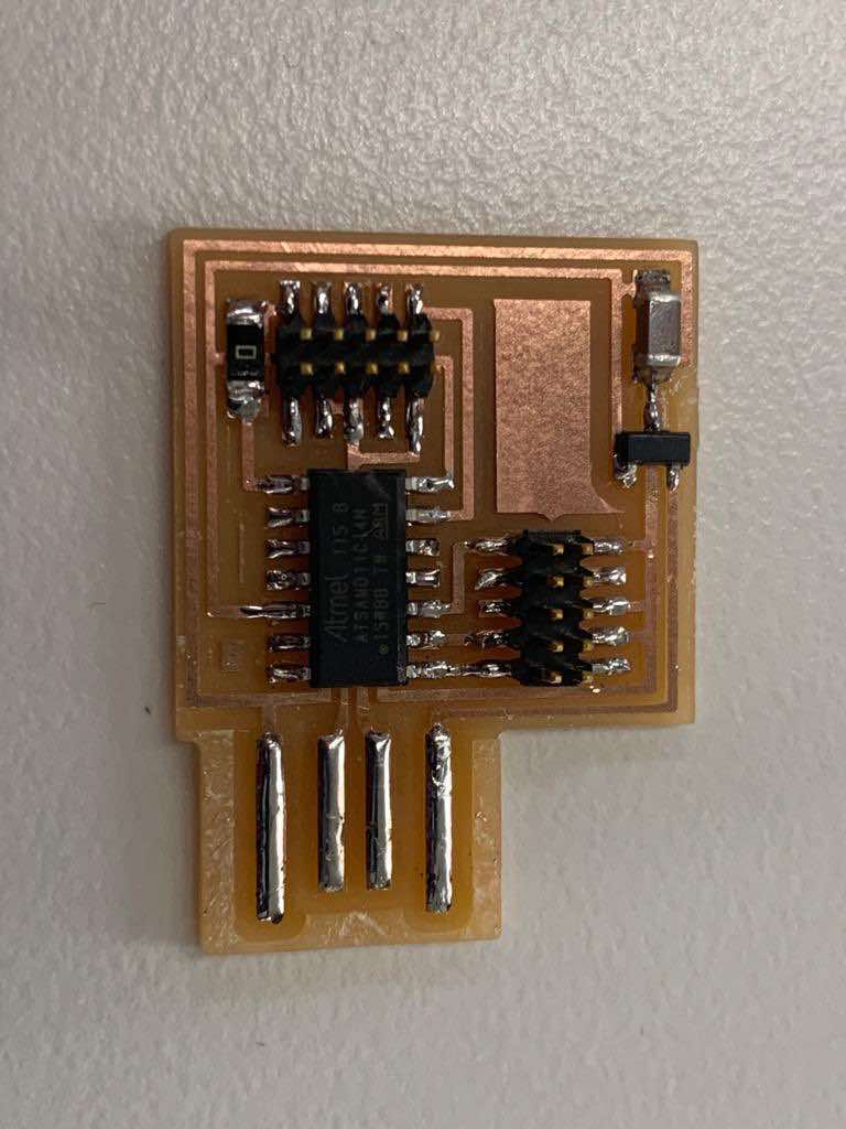
When you're done practicing, use some double-sided tape to stick your board to the table so that it doesn't move around as you work. Because our trace files actually left too much copper on the boards, (which we learned the hard way will interfere with your connections), we also had to begin by scraping off the excess lines around where the board will fit into a USB port with a blade.
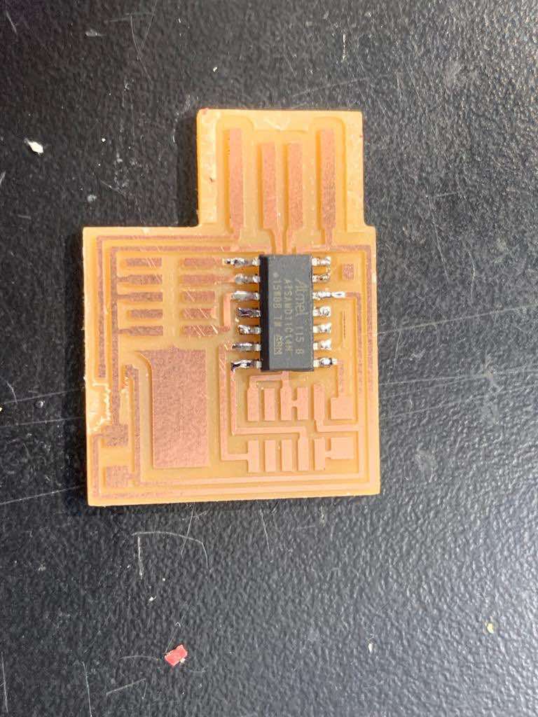
To attach components to your board, you'll first want to tack them in place. Do this by adding a tiny dot of solder to the board where one corner of your component will go. Then use forceps to position your component in place. Holding it there, come back in with your soldering iron to reheat the dot of solder you previously added. This will cause it to reflow around the component's connector, effectively holding your component in place.
Then, you can go back in with your soldering iron and wire to properly solder the rest of the connection points. (You'll probably want to add a bit more to your tack point, too.)
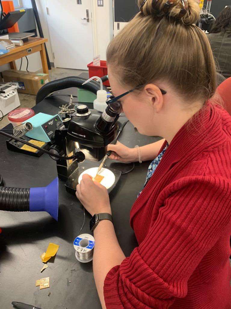
Tip: I personally found working through a microscope to be incredibly beneficial, as this allowed me to better see the tiny details I would be working with. It took some getting used to and many of my classmates chose to skip the microscope, but I'd definitely use it again next time.
Working from the middle of your board outward will help you avoid needing to reach over and around components you've already added. I also suggest starting with the most difficult pieces and progressing to the easier ones. That way if you mess the hard ones up, you haven't sunk as much time into everything else yet.
Tip: Remember you can rotate your board! There's no need to contort yourself to try to reach hard-to-access nooks and crannies on your board. Just reposition the board itself.
Time for the reckoning! Once you've soldered your board, the only way to test whether it works is to program it. If it programs successfully, you're in luck! If not, you're in for some troubleshooting. The following directions are from our wonderful TA, Leo McElroy's notes .
Our TA, Leo, suggested that we use opencd which worked for me. To install this on a mac that already has homebrew, run the command brew install opencd.
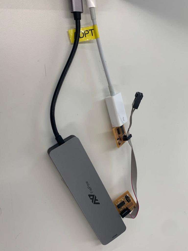 Step #2: Connect your programmers
Use a ribbon cable to connect your boards. The cable should be connected to the pins running parallel to the USB plug on the board doing the programming, and perpendicular to the USB plug on the board being programmed.
Power both boards by plugging them into a USB port connected to a computer.
Tip: the order of operations matters here! Plug in the board being programmed first. Then the board doing the programming.
Leo kindly provided us with the necessary files here .
Within the directory you just downloaded, run the command openocd
To see whether your programmer works, program someone else's board!
created with
Website Builder .