Electronics Design
(Re)designing circuit boards in Eagle to add buttons and LEDs, plus milling, soldering, and bootlegging.
(Re)designing circuit boards in Eagle to add buttons and LEDs, plus milling, soldering, and bootlegging.
Redraw an echo-hello board, add (at least) a button and LED (with current-limiting resistor) check the design rules, make it, and test that it can communicate.
Use the test equipment in your lab to observe the operation of a microcontroller circuit board.
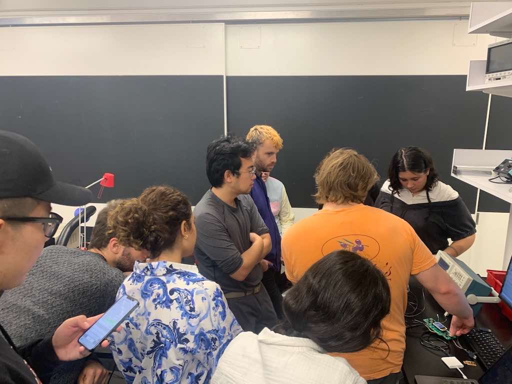
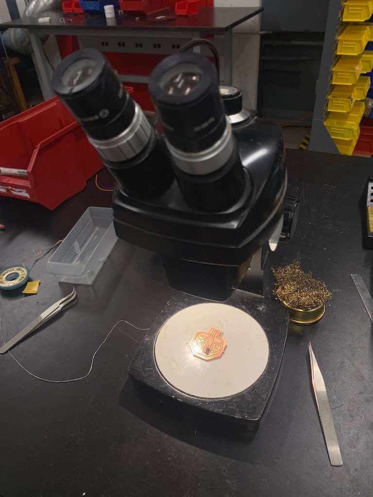
Rehana and I stopped by the lab on Thursday afternoon to tinker around with the oscilloscope.
We tested a few different boards from the "working programmer" box (specifically looking for ones that had buttoons so we could turn some things on and off) and tried out different settings on the oscilliscope to see how it reacted to them.
We eventually landed on the correct settings to see a jump in the readout!
Oscilloscopes show the waveforms of electronic signals. So, for example, you can see a visualization of square waves.
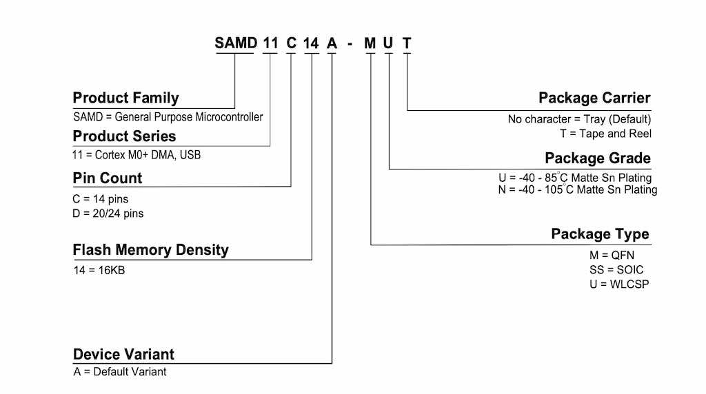
First, I had to choose which board to remix. I decided on the ATSAMD11C-echo-10 board, since this one had more pins than the original and was recommended by the TAs.
Already feeling overwhelmed, I decided to start with the smallest thing I knew (or was confident I could learn) how to do: identifying the components I'd need.
I knew this was information available to us, so treated it like a puzzle. The components had to be A) present on existing "echo hello" boards Neil provided as references, plus an LED and a switch, and B) available from the "fab library" we were provided, since this contains the components we have in stock in our lab.
(To add the library, navigate to Library Manager in Eagle and either add downloaded files or add a library from a team. In our case, the TA added us all to a Fusion Team to grant us access to the relevant library.)
First, I had to choose which board to remix. I decided on the ATSAMD11C-echo-10 board, since this one had more pins than the original and was recommended by the TAs.
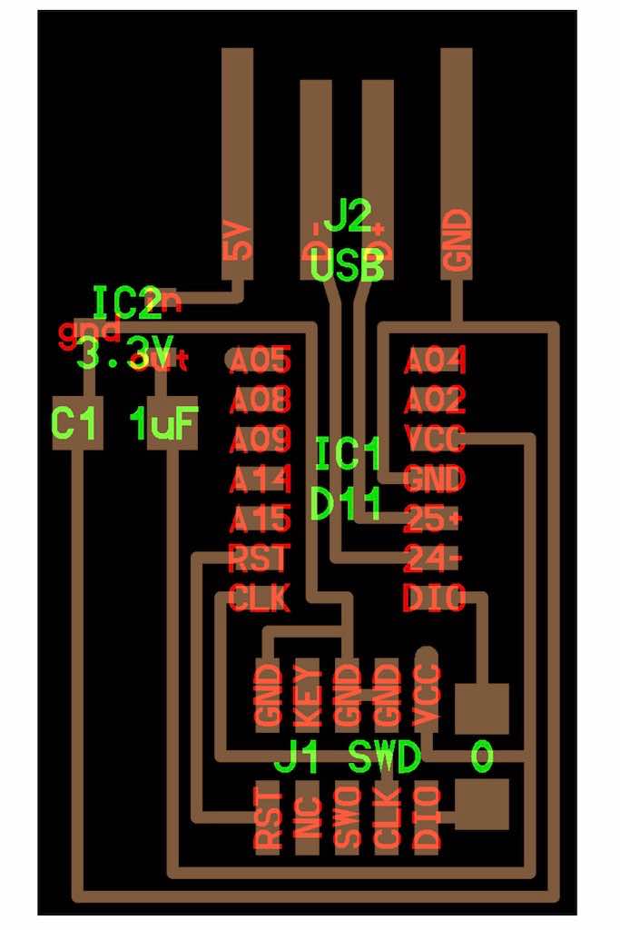
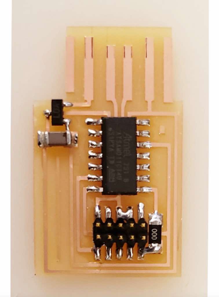
Here are the references Neil provided for this one, including a "board" view that shows a schematic perspective, and a "components" view that is really just a photograph of a finished board.
Now that I had decided on a board, I needed to do two things: 1) recreate the schematic for the board in its current form, and then 2) add a switch and an LED.
I started by identifying the various components I needed. I wrote these out on paper first, and then went into the fab library to add them to my schematic. I worked in Eagle, which is a PCB software owned by AutoDesk and therefore compatible with Fusion 360. I downloaded Eagle from the Autodesk website, and then opened it through Fusion. (This is important, since it does look a bit different when opened as a standalone program).
Do this by opening Fusion, and then navigating up to the main "file" menu. Choose "new electronics design" from this. This will open multiple file tabs acoss the top of Fusion: one for the schematic, one for the board view, and one combination document. It is absolutely vital that you don't close or delete any of these files! This will cause cascading errors.
We'll use the board view a little later, but for now we need to work within the schematic.
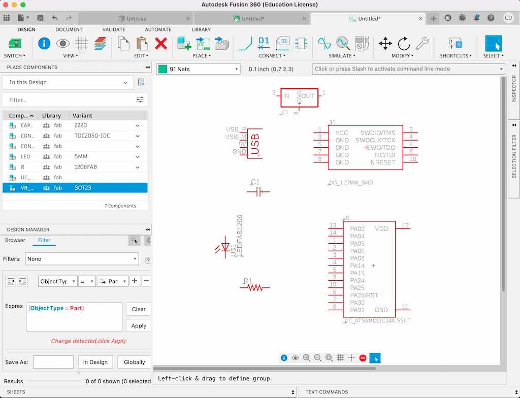
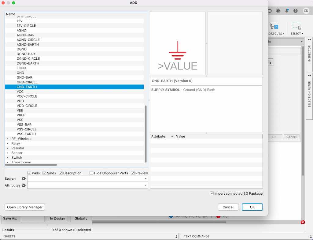
To add components, you can do three different things: 1) manually click the tetris-shaped block in the symbol menu across the top of the screen, 2), manually click on the command line and type "add" or 3) skip the mouse/trackpad and just type "/" anywhere on your screen to activate the command line to then type "add." For me, the library opened a menu on the left side of my screen. Then, once I located a component I wanted to add in that menu, I could click on it and drag my mouse over to the right. Once my mouse was over the schematic portion of the screen, the component would appear and I could drop it wherever I wanted it.
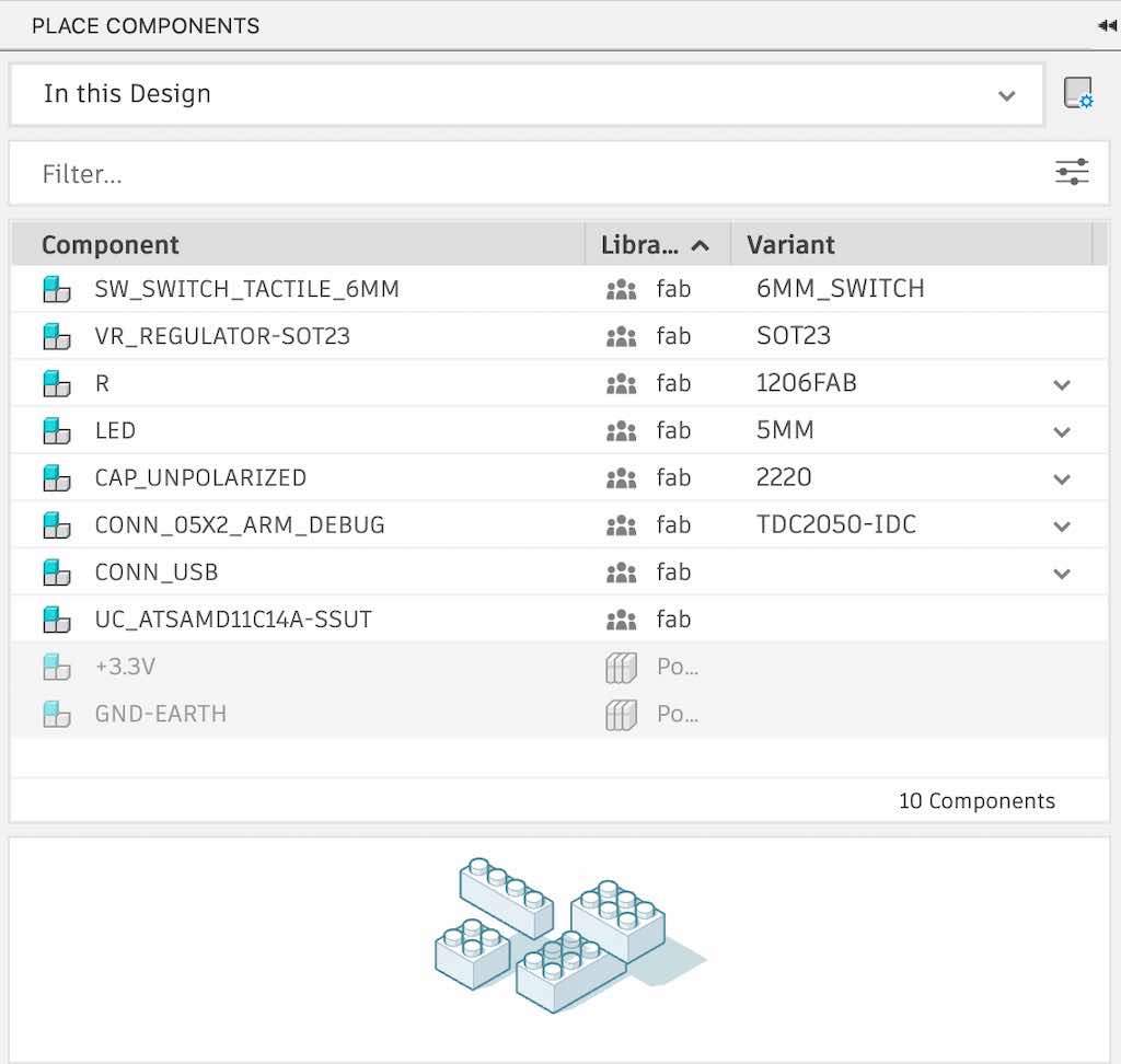
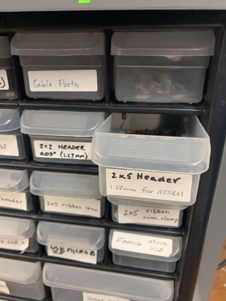
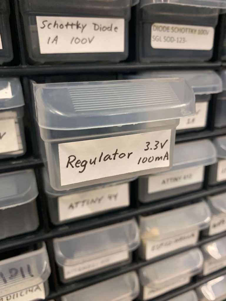
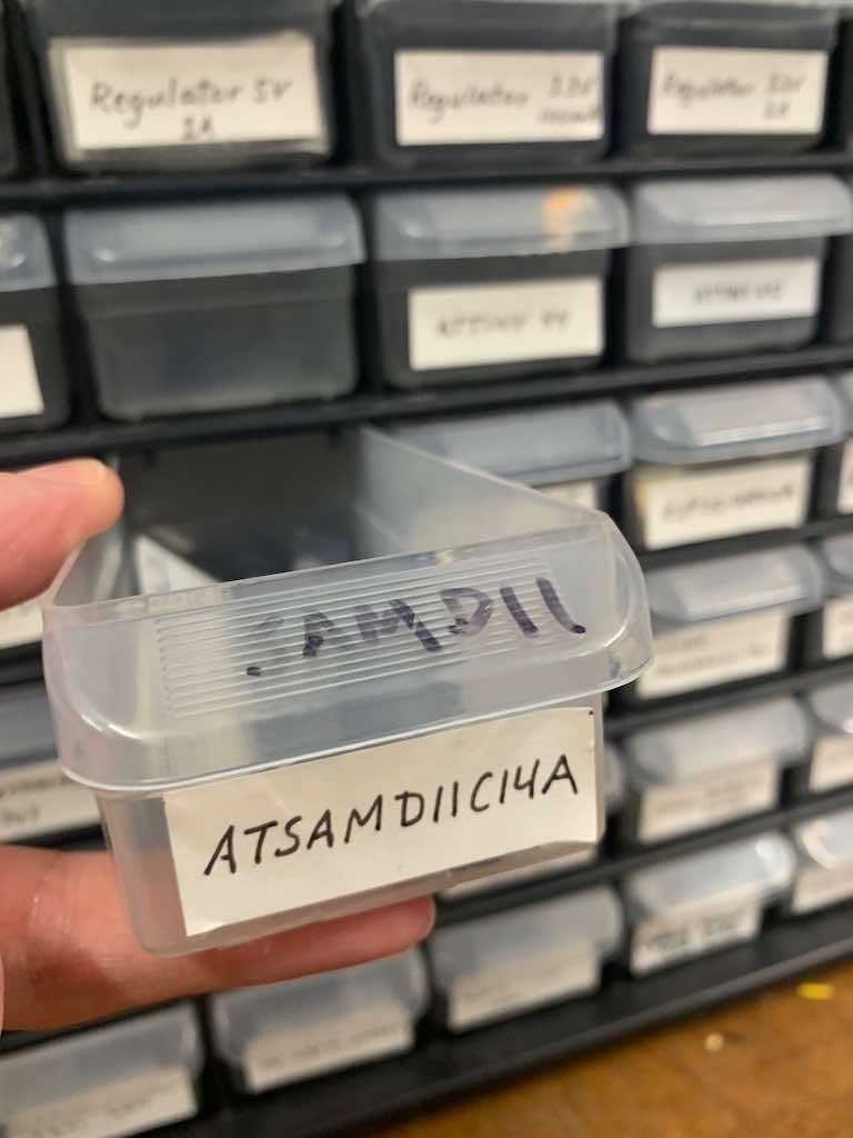
Here is how the necessary components I'd identified were labeled in the fab library:
If you don't know where else to start, I strongly recommend identifying the components you'll need and laying them out in a new electronics design schematic.
Although it still feels overwhelming, it really helps to feel like you at least have the pieces of your puzzle finally laid out! Now you have something concrete to work with.
The next step will be to figure out how all of these pieces will interconnect.
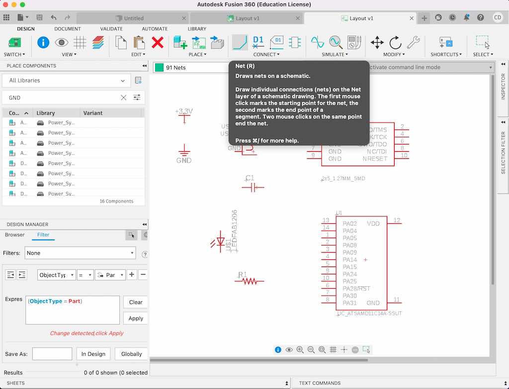
Now that we have our pieces laid out, we're going to rearrange those components to create a bit more visual organization and then draw "nets" between them. (These nets are integral in your next step when you'll route your traces.)
Nets in this context are just thin lines that show you which pieces need to connect to which.
To draw a net, either click the aqua "net" icon in the "connect" menu or type "net" using the command function. Then click on an origin for your net (probably a component) and pull the net to your target location (probably another component). To create hard angles if you need to navigate around other things, you can click to essentially pin it in place and then keep going from there.
The goal with this is to connect all of the components to each other (or to ground) in the proper pattern to make a complete, functional circuit.
It may be helpful to turn the visible grid on to help you make sense of what you're looking at. To do this, type "grid" into the command line.
Note: I moved components around a bit on the screen at this stage to make more sense of them, but this doesn't need to be pretty! It's okay at this point to cross one net with another, or branch one off to another component that needs to connect to the same thing. The next step is where we're more limited - for now, just organize things in a way that makes sense to you.
Tip: If you're getting too confused with lots of crossed nets, there's also another way make your connections. Instead of drawing solid lines between things you want to connect, draw a short net to nowhere. Then name it (use the command "name") something. Repeat this process on the component you want to connect the first one to, and name it the same thing, and select "yes" when an automatic pop up asks you if you want to connect these two nets. Now you have a connection without lots of lines! You can also do the same thing with symbols, like 3.3V and groudn symbols. Although some people find this faster and easier, I'm a very visual person and preferred to stick with solid lines so I could see the full sequence for things (although I did use symbols for ground).
The easiest way to do this is to pull up Neil's reference diagram and map out how different components are connected. (I mean this literally - I used my finger to follow traces to figure out where they go, and then draw nets to mimic these paths.)
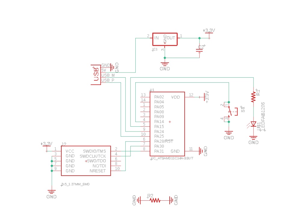
Keep in mind that in order to add the LED, you'll also need a resistor. The power should flow to the resistor first, and then the light.
Although I initially laid out the button, resistor, and light in a single sequence, I soon learned that this was a very limited approach. Although it would allow my light to turn on and off, I wouldn't have any flexibility to do anything else.
Connecting the LED to one pin and the button to another allows us to program different behaviors later on. I pivoted to this approach.
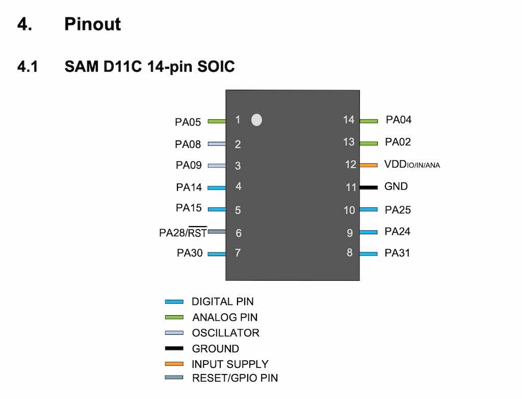
Since both components would need to be on gpio or digital pins, I looked up the data sheet for my chip to determine what the different pin types were.
Now comes the hardest part (for me, at least). It's time to actually route your traces, meaning you'll draw a more formal, constrained map between components. What you create here will be exactly what gets milled.
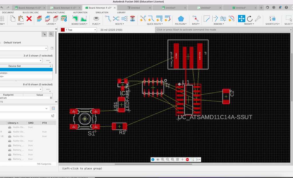
To get started, navigate to your board view tab. What you see will be a terrifying, tangled mess. Don't panic. We'll tackle this shortly, but first we need to do some housekeeping.
I found it helpful to turn the visible grid on again here. Type "grid" into the command line to do this.
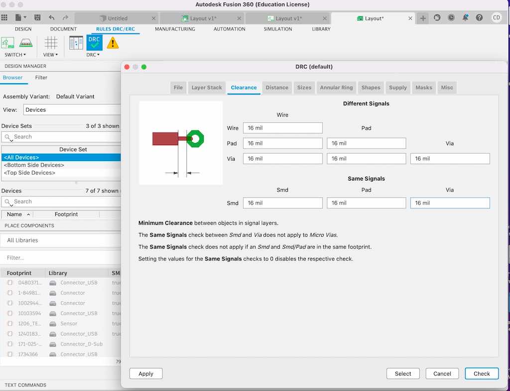
Setting Up Design Rules: These are based on the tests we ran two weeks ago as a class, as well as best practices recommended by Neil and the TAs. There are two main rules to keep in mind to make these boards millable and hand-solderable: clearance and trace width. "Clearance" takes some navigating to find. Open the board view, and look to the text menu across the top of the screen. Choose "Rules DRC/ERC." Your icon menu should now update to reflect this selection. Click on "DRC," which should show a green checkmark icon. This will open a new pop-up menu. Select the tab labeled "Clearance" and update all of the figures to at least 16mil. This ensurers that there is a wide enough buffer between your various traces/pads/features and between your features and the board's perimeter to allow you to cleanly mill and solder it.
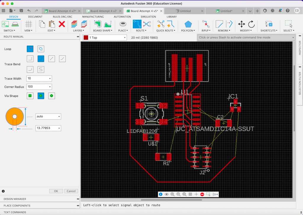
Once your design rules are set for the clearance, you want to click back over to the "Design" toolbar. Now either select the "route" icon (a blue line connecting two blue dots) from the top menu, or activate the command line to start routing (command = "route"). A menu should appear.
Set your trace width to 16. We tried a few different widths, and the TAs recommended this one. It does seem to be the best compromise in terms of being thin enough to manuever beneath raised/bridge-like components like resistors, and still wide enough to mill nicely. (You can also drop down to a thinner trace if needed, for short distances.)
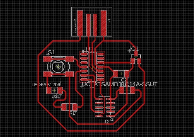
With our design rules configured, it's finally time to route the traces!
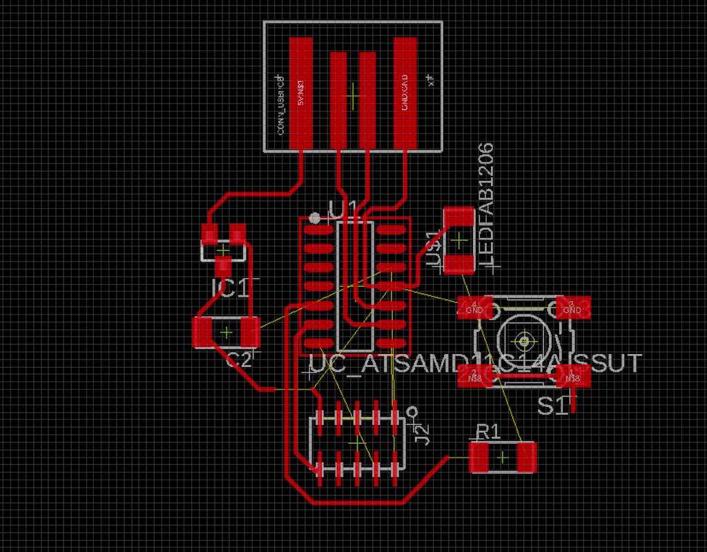
The tangled mess we're looking at is a representation of the nets and connections we made during the last step.
The little yellow lines between components in this board view are called "air wires." They just indicate which components need to be connected to which. They will also automatically seek out the closest relevant connection point as you move a component around your layout. Some have several possible connections (like grounds).
Our goal is to lay the components out in such a way as to minimize crossovers (or as I think of them, tangles), and to route traces between them in as simple and streamlined a pattern as possible.
To route a trace, either use a "route" command or click the icon that looks like a single blue line connecting two blue dots. Now drag and click to lay your traces, connecting components that are air wired together. Try to avoid getting tangled!
Note: to get rid of a trace, the command is "rip-up" (not delete).
If you need to jump one trace with another (you can't cross them), you can use a zero-ohm resistor to create a bridge. Do this by navigating back to your schematic and adding a resistor anywhere on the board. Net it to itself (so essentially draw a circle with the nets connecting one end of the resistor to the other). Then use the "name" command to name it what you want to connect it to. When this appears on your board design, you can use it as a bridge.
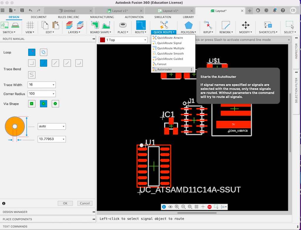
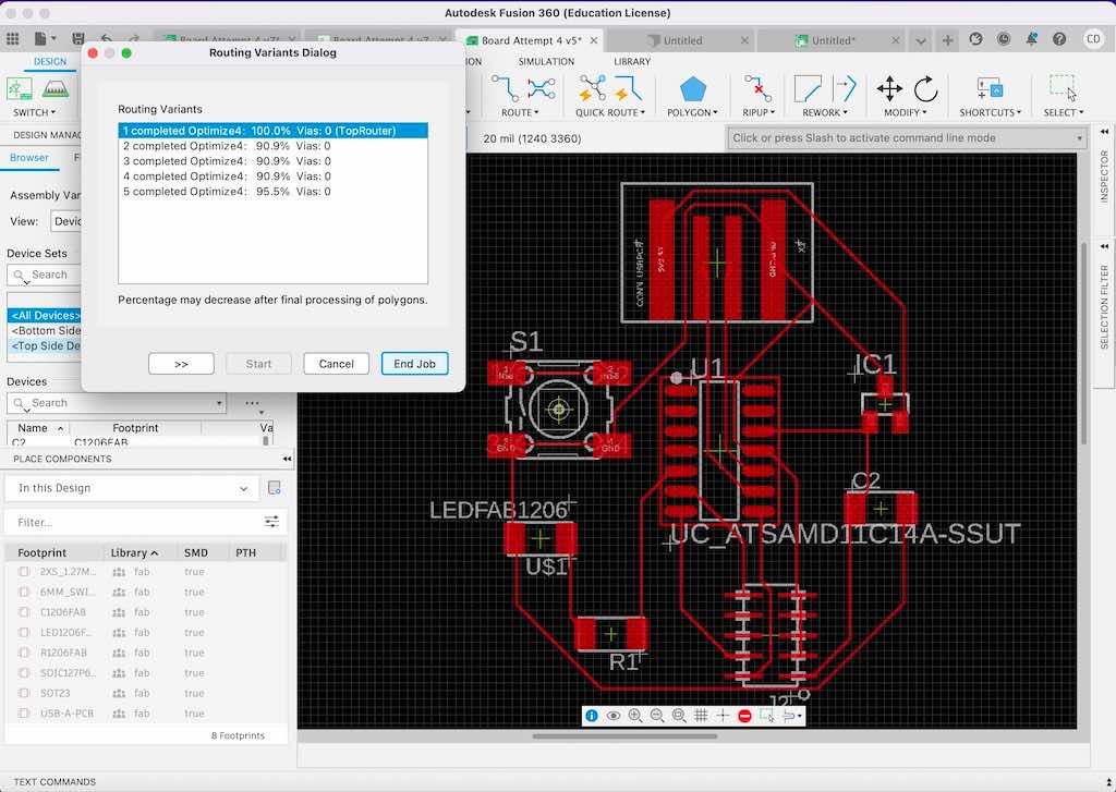
Pro Tip: If you're really stumped on something, you can click on "quick route" and then choose "autorouter" from the drop-down menu. In the pop-up menu that will populate, make sure to toggle box 16 to N/A. Don't use the autorouter as a whole because it won't help much unless you're already pretty close to done, but it can help you understand whether you need to add a resistor to jump something or whether there's an easier route you're overlooking for a particular trace.
I personally found it useful to refer to Neil's simple board layout when working on mine, and then to add my button and light from there.
There's no life-changing advice for how to route your traces as far as I'm aware. You just have to puzzle it out, but it gets easier as you go.
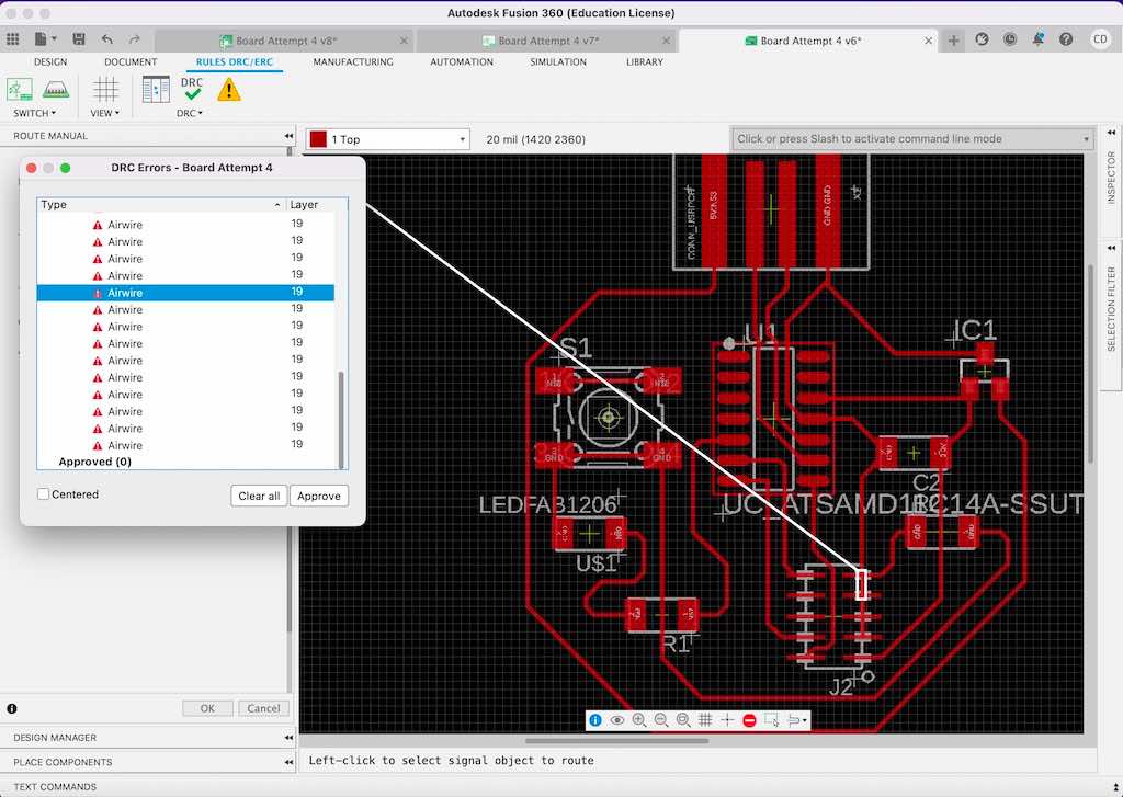
Check for Errors: I do suggest that you check for errors once you think you're done. Navigate to "Rules DRC/ERC" again and click on the orange triangle with the exclamation point in it. If you click on any of the error lines that comes up, the software will highlight the issue. (Note that if you added a resistor as a jump or bridge, the software doesn't understand that. It will leave an air wire in place asking you to connect it to itself with traces, but don't do that. Just ignore that particular error.)
Pro Tip: You can narrow your traces for short distances, especially if you want to run them under/through the microcontroller or header pins. I did this to fit three traces in parallel from my USB through the middle of my microcontrorller. Don't reduce your trae size below 8, though.
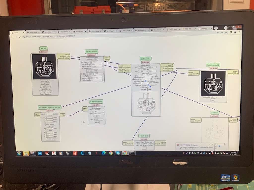
Once your traces are added, you'll want to export the various layers of your design so that you can load them into Mods.
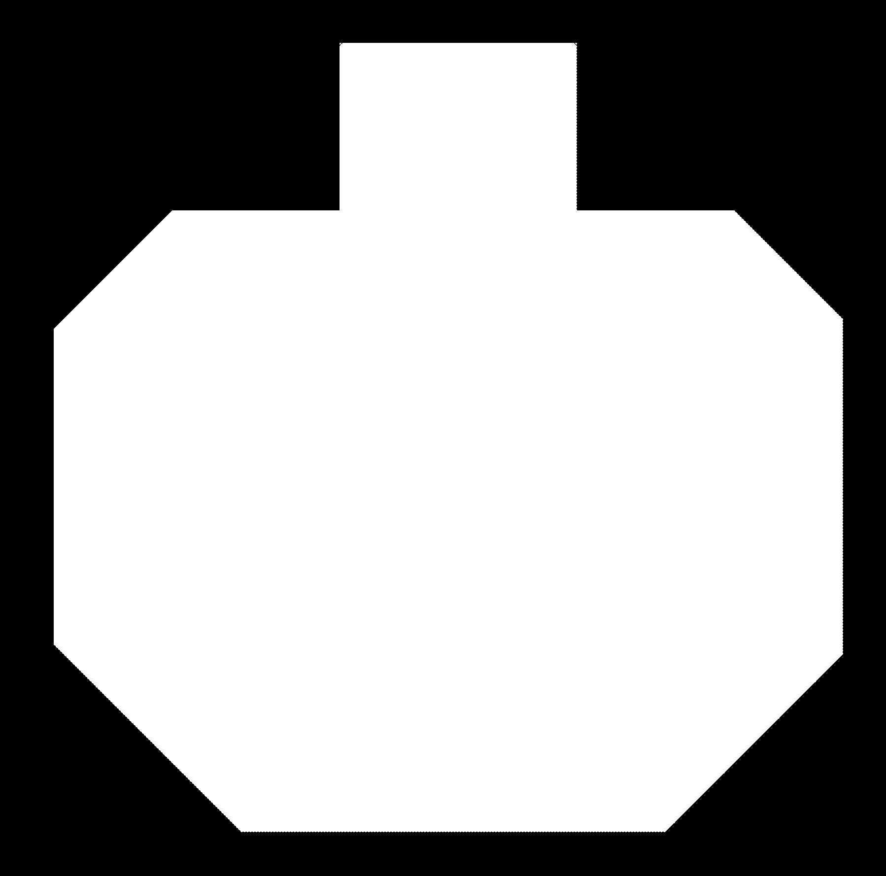
Outline file: First, you need to create the background layer. This is the shape or perimeter of your board—the outline the mill cuts out. To create this, select "polygon" (the blue pentagon in the icon menu) from the design menu. Then trace around your board. (Note: I found it easiest to create this in a different layer so that I had two different elements to export. I used layer #16, the back, since I didn't have a back to my board anyway.)
Enter command "display none." Then select layer 16 (the dimensions layer) again. You should now only see the outline you just made, with no other pads or traces visible.
Next, enter the command "export." Navigate down to "image." In the pop-up menu, check the box for monochrome. Then update the resolution to 800. Choose a file name. (This will be your outline file, so I suggest naming it as such.) Save it! It will automatically save within Eagle - I suggest saving it to your desktop instead.
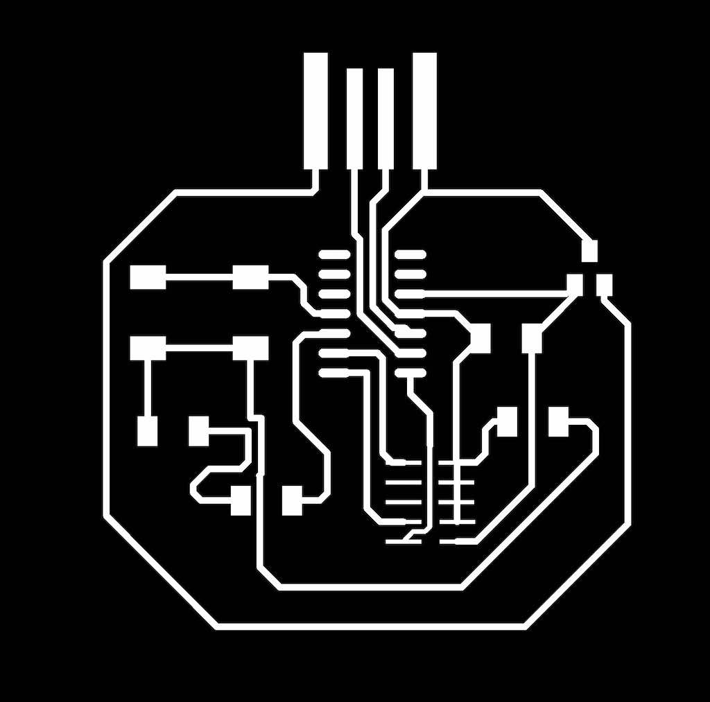
Traces file: Finally, WITHOUT changing anything about your screen or zooming in or out, enter the command "display none" again. Then select the top layer. Now, you should see just your pads and traces but NOT the outline you made earlier. Enter command "export" again and repeat the saving process. (Make sure the box is checked for monochrome!) This will be your traces file.
Now you should have two .png files ready to load into Mods and mill!
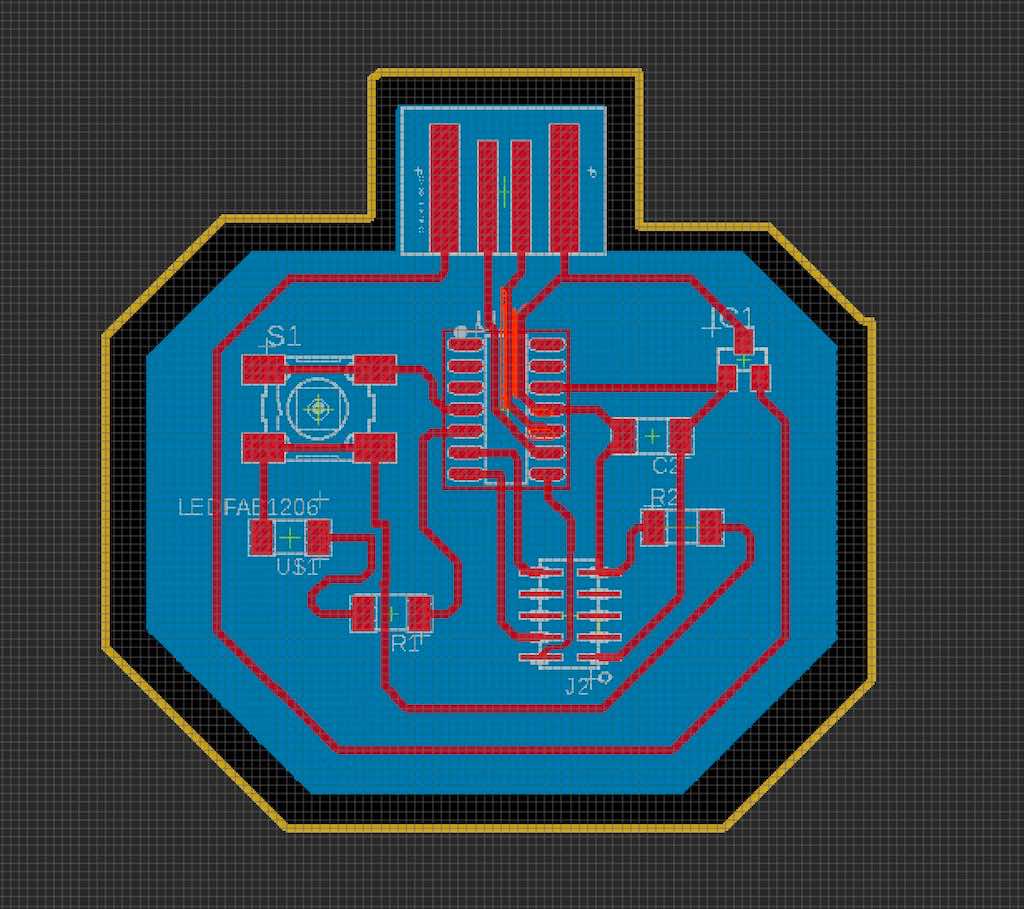
Learn from my mistakes: I did this step in an inefficient way, personally. The process I outlined above is the better way to do it, which I eventually figured out. However, I initially created my board outline on the dimensions layer as you can see below, using a yellow line. This resulted in an extra perimeter being milled around my finished board. It didn't compromise the board itself, since it just cut an extra outline out - but it was wasteful of both time and material, and completely unecessary. You can see the double line in the first and last images below. The blue footprint in the first image is my desired board footprint, while the yellow outline around it is the unnecessary extra outline. in the last image below, you can see what my "outline" file looked like as a result, when I exported it.
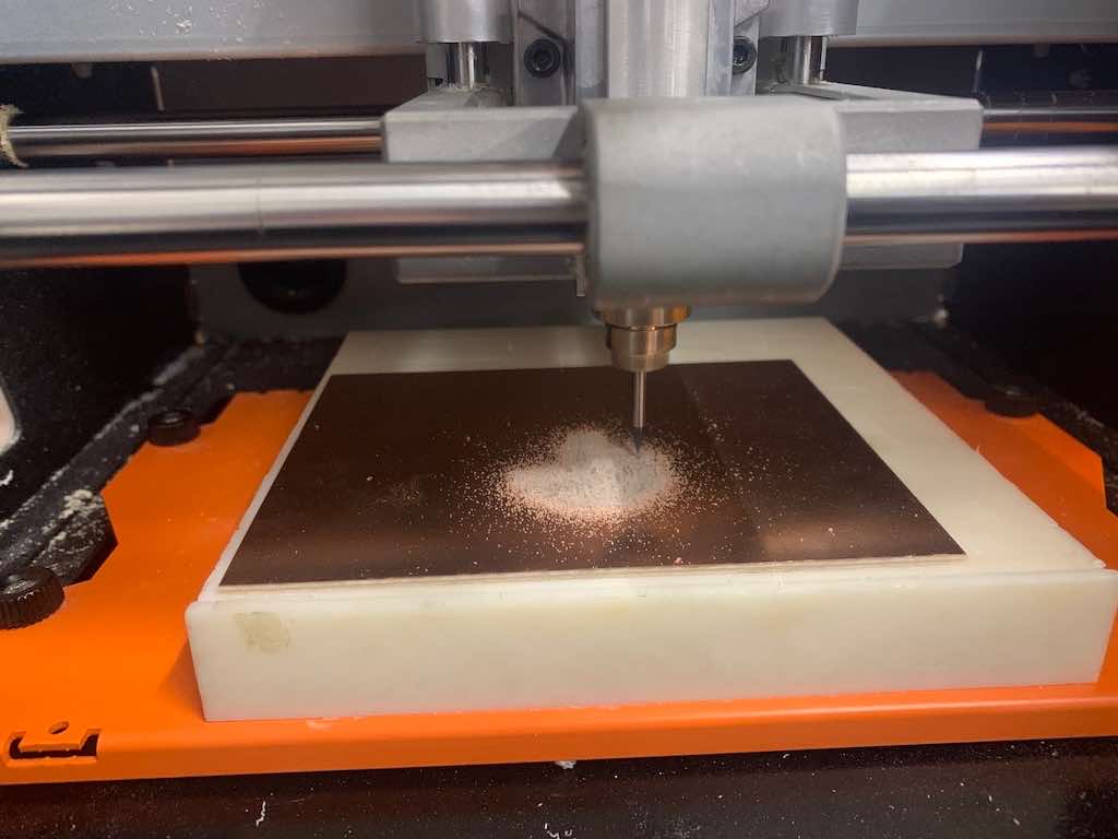
The milling step for this week works just the same as week #3, so look back to that week if you need guidance.
My section had a rough time with the Roland for some reason, as it seemed that the bed was out of alignment. There were several spots where it refused to cut through the top copper layer.
Neil always says the machine is predictable, so any errors are probably in your design file. This is generally true, but in this case it's been predictably unpredictable, behaving the same peculiar way for all of us. So, probably not a file issue.
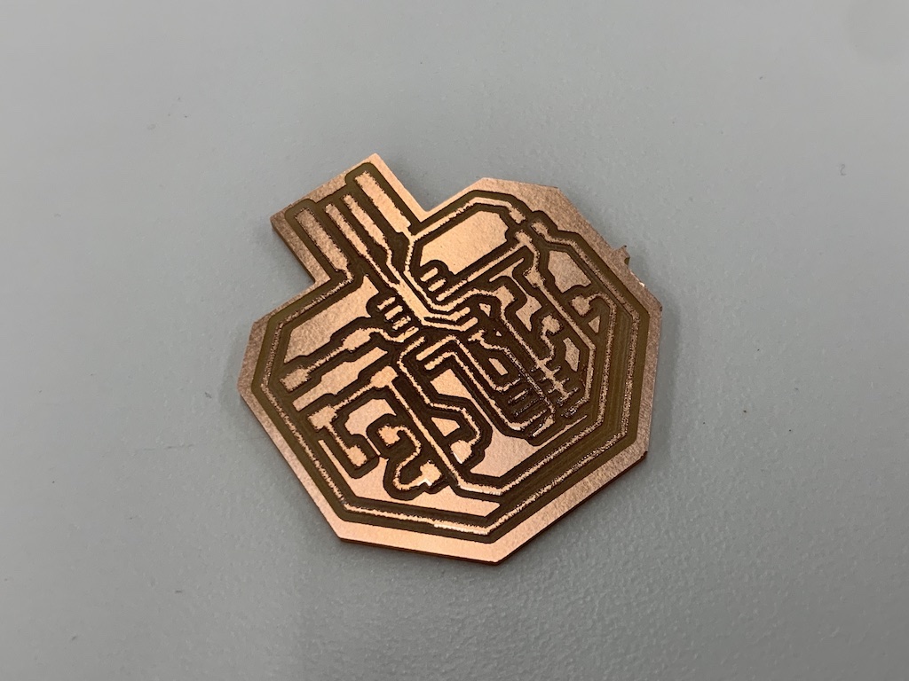
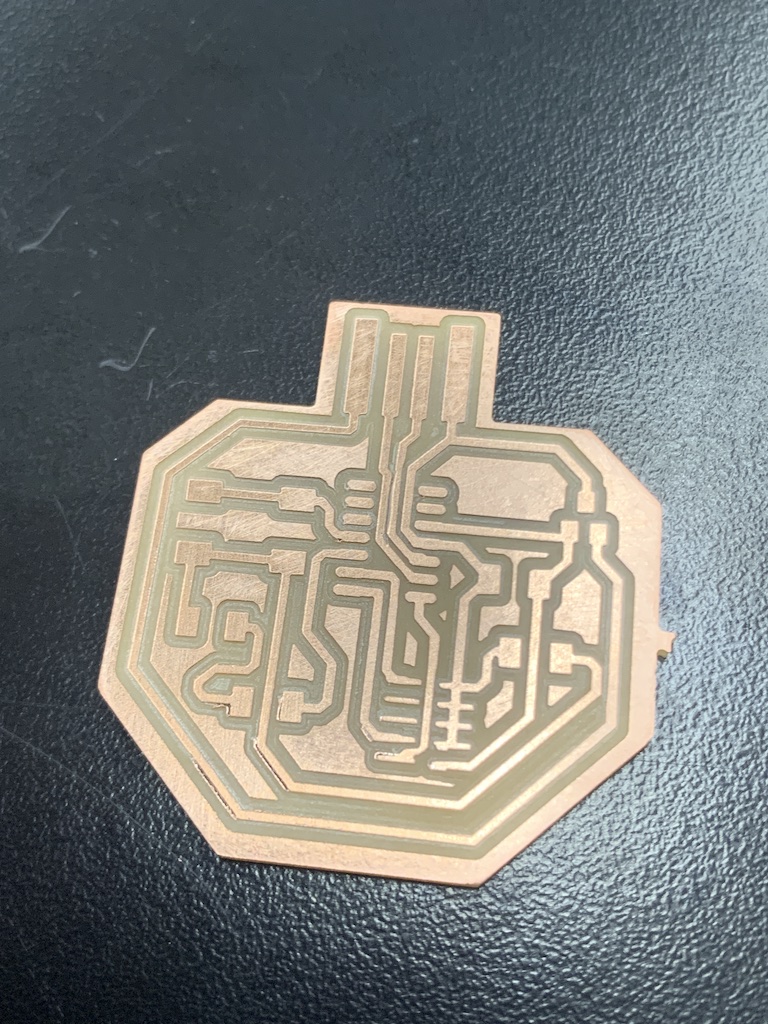
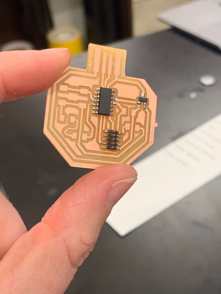
My board looked a little rough after milling, and I actually ran into an issue: two of my traces leading down from my USB bled together. If this happens to you, don't panic!
I was able to salvage the board by using a knife to (very carefully) cut a line to separate the traces. You can see the difference in the last image below. Then I sanded the board to get rid of all of the tiny copper debris and clean it up.
More soldering! This is actually one of the easier steps this week. (If you need help with soldering, refer to week 3.)
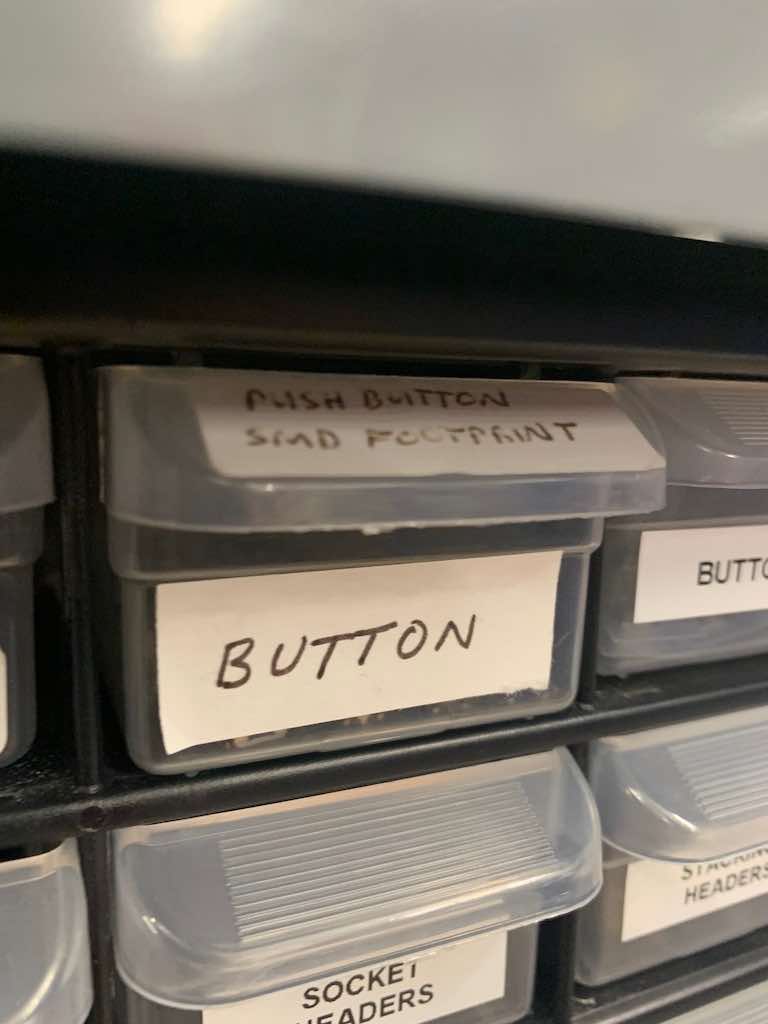
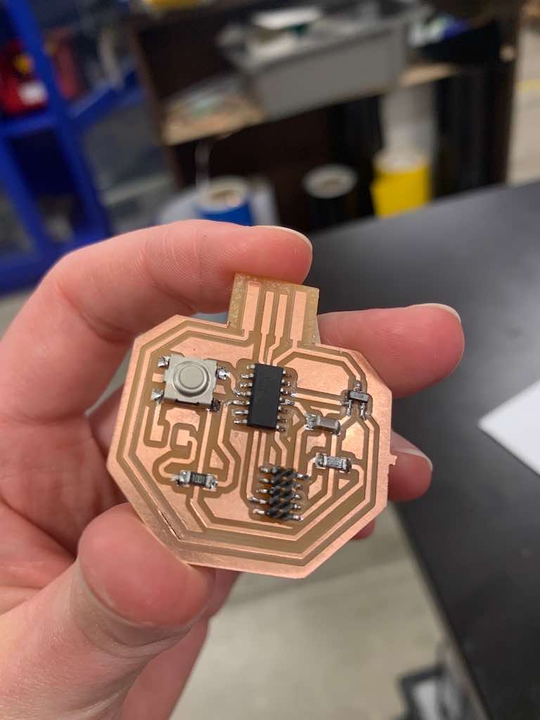
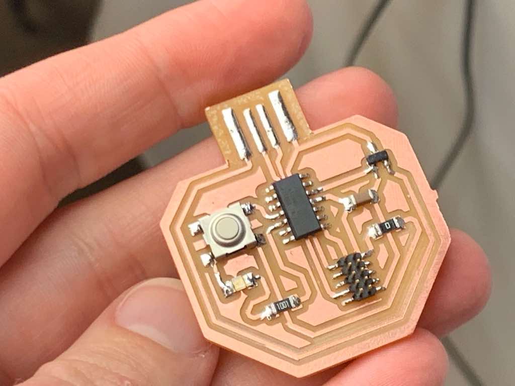
First, I identified and located all of the pieces I needed. Then I got to work!
I actually like soldering, so this was a fun exercise. See below for progress shots.
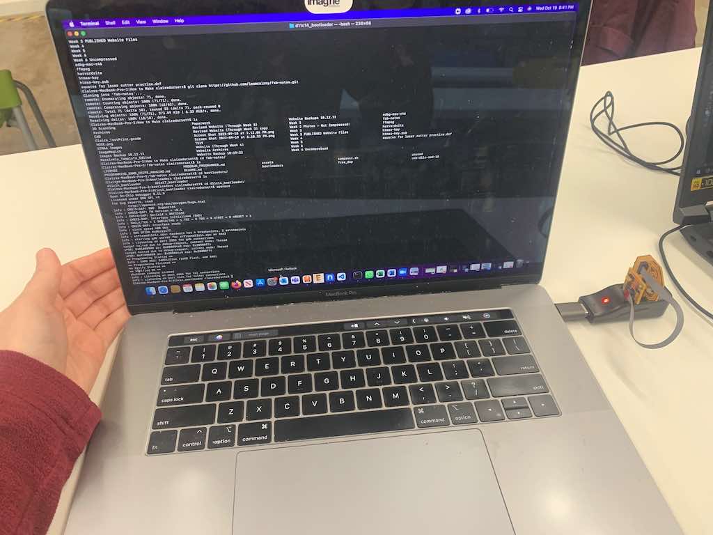
Once I was done soldering, I plugged my board in alongside the programmer i made two weeks ago, connecting the two via a ribbon cable.
Last week's programmer acts as a conduit to allow me to add programs to my new board.
At first, I had a few problems getting my pumpkin board to cooperate... maybe because I tinned the USB pins against Neil's recommendation (though to be fair, I didn't remember this recommendation at all until he reminded me in class). This meant I might not be getting even contact with all of the traces. In other words, I might be receiving power but not data. To try to balance out my contact, I added a shim behind the board made out of a folded piece of paper.
This worked! This week was a success (after a little board surgery, separating two traces), and I didn't even have to mill more than once!
created with
Website Builder .