
Computer-Controlled Cutting
A crash course in website design, vinyl cutting, laser cutting, and parametric design in Fusion 360
This week, Neil ran through some basics we'd need to know in order to build our websites (this website!) on gitlab. (Lots of pushing and pulling and some traffic jams called "merge conflicts.") He also introduced us to the wonders of computer-controlled cutting, which we'll be putting into practice with the laser cutter. In lab, we got trained on the laser cutter and vinyl cutter. Recitation ran us through more website building wisdom. A few favorite takeaways:
You're looking at it!
I had never even opened a terminal window before last week's class, and definitely associated the green and white text against a black screen with hackers and viruses. However, Cameron taught us how to generate an ssh key and clone the class repo to our computers so we can work our documentation.
A few of us, myself included, ran into issues getting the repo to clone, but we eventually discovered that this was because we were on the MIT guest server, and got it figured out.
Because I wasn't sure where to start in terms of actually building my site and didn't want that to hold me back from accomplishing other tasks for the week, I started by documenting my progress in the notes app on my desktop. This helped me keep a record of what I was doing as I went so I didn't have to try to remember it all later.
Since Neil emphasized that documentation is one of the most important things we'll do this semester, I figured it was better to have something recorded than nothing. Small spirals, after all! I knew I could accomplish documentation on the notepad for now, so started there. Then I transfered those notes into html (my first time working in html!) to put online. In the future, I hope to use a template to make my website slighly less bare minimum... but you've got to start somewhere.
To my pleasant surprise, html hasn't been quite as terrifying as I initially thought, though I'm still looking forward to learning a bit more to customize my site.
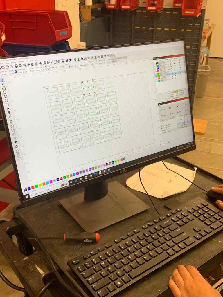
Three tries to get this right, but lots of learning along the way. They do say the third time is the charm!
Rehana and I worked on this "group project" together. To be honest, we were intimidated when we first arrived to the lab and found another group nearly done, with beautifully engraving-labeled hexagons. But we decided to figurer it out, and it honestly taught me a ton to do it from scratch! We learned quite a bit from each other, too.
I started by creating a sketch of a 2" x 2" square in Fusion, which took me an embarassingly long time because I am completely new to CAD software. I was trying to figure out how to copy+paste this a billion times (or at least 16), but then my new friend PK taught me how to use "pattern" to re-create this in a grid to get as many as I needed to run our test.
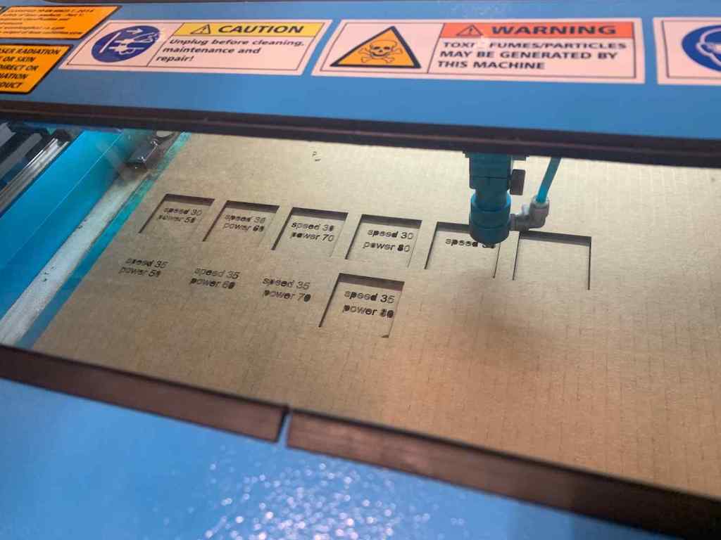
PK also taught me how to save my file as a .dxf so I could transfer my work over to the laser cutter. There, Rehana set the layers to their respective speed/power configurations and added text to label each square. This took quite a while because each one had to be programmed individually with different settings.
The first time we ran the laser cutter, we were surprised that the squares cut in a different order than we expected them to, meaning the engraving (rastering) happened after the cutting instead of before. Not optimal, but not the end of the world... but the real issue was that the laser seemed to get "stuck" going back and forth over one of the blocks. We made sure the "pass" settings were correct, double checked the other settings (or thought we did) and then decided to wait until the next day to ask a TF.
That night at home, I downloaded a free trial of LightBurn (the laser cutter control software) to my laptop. I wanted to reconfigure the file and try to get more familiar with what was happening. We tried this new version the next day... but the same thing happened again! Eventually, we realized this was occurring because "fill" was selected instead of "line," meaning the laser would have slowly burned away the entire box if we had allowed it to keep going, filling in its full interior. We hadn't known to look for that particular setting. Oops.
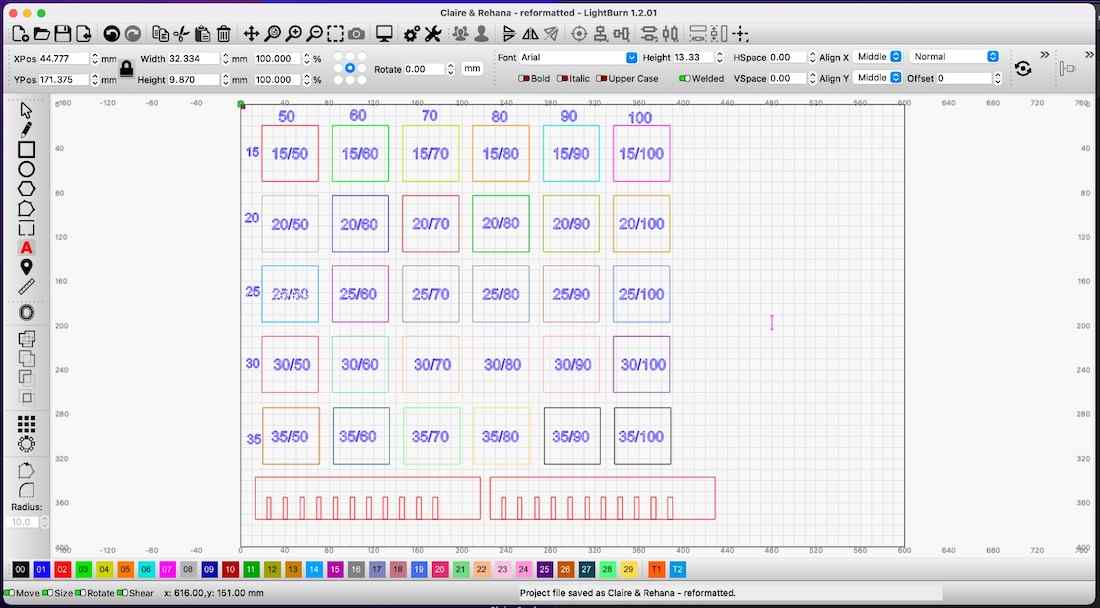
We also learned that the order in which different layers get cut depends on the order they're listed in the pop-up control menu on the righthand side of the screen; not their assigned number which appears across the bottom of the screen. Good to know for future reference.
I went back and fixed the file settings one last time, and then reordered the layers so we would engrave our numerical labels before cutting out the perimeters of our squares. This worked much better... until we hit another box that was still accidentally set to "fill." We didn't want to start AGAIN with a new piece of cardboard, so stopped the laser cutter, left our cardboard in position, and figured out a workaround.
First, we deleted all of the boxes and text that had already been cut... but this bumped the laser's starting point, which we knew by running it in "frame" mode to see the perimeter of the area where it would cut, meaning the whole job was shifted. Then Rehana had the great idea to add something small in the very top upper left corner near where our first square had originally been, so we did that... and it worked! (Later, I noticed that there is a setting you can toggle on that lets you only cut selected shapes... good to know that much simpler solution is there for future reference.) You can see a small scar on the bottom edge of one of the squares in the pentultimate row from this small blunder, but we're proud that we figured out a work around.
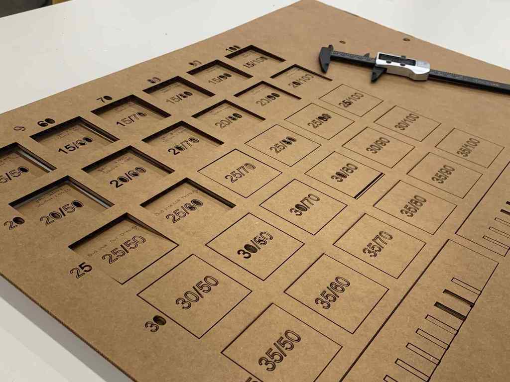 Once the cutting was done, we were able to see which squares cut all the way through and which did not. By measuring the squares and subtracting their width from the width of the opening they left behind, we were able to deduce the laser's kerf. (The optimal setting for the smallest kerf seemed to be at 20/90, with a .3mm kerf based on our test, but we realized later that the laser cutter isn't working well in the lower righthand quadrant of the bed, which may have skewed our results).
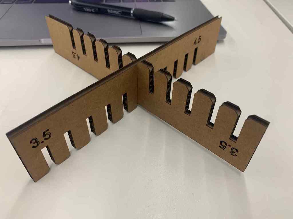
Then I created a "comb" in Fusion to test different fits between pieces. I made a bunch of smaller rectangles, each the same height but with different widths (varying from 3.5mm up to 4.5mm in .1mm increments). These smaller rectangles represented what would later become the spaces between the "teeth" on my comb.
I had trouble at first creating "holes" from these in my extruded object, and then grew frustrated again when I had to manually position tthem across the width of my comb... I wanted an option to just distribute them evenly across that distance. I'm sure there's a better way. I just haven't learned it yet. (Update: I could have patterned them into a single row using the rectangular patterning tool!)
Cutting these combs allowed us to see which slot widths fit together most snugly, which we'll then use throughout the rest of the project to create our parametric designs.
I initially tackled this at HGSE's Education Innovation Studio since I was more comfortable there to begin with.
First, I got trained on the vinyl cutter. Then I worked on finding a vector image I could use to make a vinyl sticker. I chose a cactus for no real reason beyond the fact that it was cute and I could find a free file for it. I set this up in Corel Draw since that's what the HGSE vinyl cutter uses. That meant making sure it was a hairline outline since it only cuts hairline lines.
My first attempt vinyl cutting was only so-so. I asked the lab monitor how frequently we need to replace the blades on the vinyl cutter, and was surprised when he said he doesn't think we have ever replaced them. In the FAS lab, the expectation is that they get replaced between each project. Definitely polar opposite ends of the spectrum there, which seems to be the case for a lot of things between the EIS and FAS labs. Interesting!
My second attempt came out better. It was exciting to see the shape take form once I weeded it (weeding = removing everything you don't want.) It was tricky to weed the tiniest bits, though.
I also joined Rehana to cut a Harvard "H" on the FAS vinyl cutter. We had a bit of trouble getting the program to connect to the printer. This turned out to be because the terminal that goes with it wasn't open and running. Once we got this fixed, we were good to go!
This was a daunting task, and in all honesty I found it quite difficult. But office hours with Alfonso helped immensely, as did PK's guidance! I am incredibly proud of my end result.
I started by trying to make a square. (My smallest spiral in terms of project management and reralistic achievability.) Then angled connectors for it. (Another spiral up). Then, I decided to try to re-create an icosidodecahedron. That's a ball made of twenty triangles and twelve pentagons joined together in a repeating pattern. That meant creating more subtly angled connectors, as well as parametric triangles and pentagons. Everything would have to match up perfectly. A giant leap in terms of spirals for someone as new to this as I am!
To start, I spent a long time fighting with Fusion. I mean it: a very long time. As Neil said in class, it's an incredibly powerful program--but that means it also has an incredibly steep learning curve.
Of the scores of online tutorials I looked at, none were helpful for the most basic of my questions... and I'm talking basic. Like trying to figure out how to toggle back and forth between dimension fields for a rectangle (hint: use the tab key). So, to any beginners reading this in the future: it's okay to feel completely overwhelmed. You'll be alright. (Go to office hours! Ask people in your section.)
After a lot of tinkering around, I eventually figured out how to set parameters and assign them to dimensions, and I'd already learned from the group assignment how to extrude... but making a polygon with slots that had similar geometry on all sides threw me for a loop.
At this point, I had some legitimate panic, but Neil assured me that beginners have a steep learning curve and it would be okay, and then pointed me to Alfonso's office hours. They were EXACTLY what I needed. (THANK YOU, ALFONSO!)
I started with squares, which I parameterized the side lengths of. Then Alfonso taught me how to reflect something I'd designed across a line (we used construction lines for this). So, by finding the midpoint of one of my square's sides and drawing a construction line, I could mirror a design feature across it. I did this to create the slots for my cardboad, giving them the parameter of "thickness/2" (they are divided by two since I mirror them across a construction line, therefore combining two and ultimately making my thickness measurement whole).
Then, I created a center point in the middle of my square and used the circular patterning tool (with number = 4) to pattern my slots around all four sides of my square. Success!
Then I extruded the sketch to my material thickness. From there, I selected all of the slot's corners and chamfered them (after first assigning a parameter for chamfer). Pro Tip for those on a Mac: I learned at this point that holding command+shift and scrolling with two fingers let me move around my object while selecting things! Then I selected my square's corners and filleted them. (Another parameter!)
To create right-angle connectors for my squares, I created a new sketch. In this, I drew a long rectangle and set parameters for its long sides. For its short sides, I parameterized a function (4*thickness).Then I created a slot on on end just like I did for the square. To create my right angle, I think duplicated the sketch and rotated it, superimposing this new version on the first and assigning a coincident point to keep them together. Then I extruded, added my chamfers, and filleted the corner.
However, there's an easier way to do this! Alfonso showed us how to draw a construction line at a 45-degree angle to my first rectangle. Then I trimmed the extra bits of rectangle, and reflected it across the construction line. Brilliant! I was so proud that this worked.
This technically satisfied the assignment, but I was determined to use my newfound skills to create something more complex.
I went back to the lab and followed the same process to create a triangle, and then a pentagon. (More reflecting across construction lines! More patterning!) These got parameterized with identical side lengths. I assigned my thickness as 4mm even though cardboard is closer to 4.5mm because I knew from the combs I created for the group project that these slotted together the best. (I'm so glad I did the group assignment! It felt like a nightmare at the time, but I learned so much.)
To create my angles, I looked up the angles of an icosidodecahedron on Wikipedia. Then I did some fun reflecting and created a shape with the appropriate angle. In retrospect, I should have parameterized the angle itself so I could adjust its degree to apply the same piece more easily to other geometry... but I've only just thought of that while I'm typing this, so it'll have to be something for next time. Then I extruded, and it worked!
Key Takeaways:
In the end, it worked! I built my ball out of triangles and pentagons. Then I immediately disassembled it because it was raining and I didn't want to ruin it on the trek home. A bummer after all that work, but also easier to carry on my way to MIT tomorrow from Harvard.
created with
Website Builder .