Week 14
System Integration
System Integration Highlights
Key moments from the final system integration week, showcasing the complete MirrorAge system assembly, testing, and presentation.
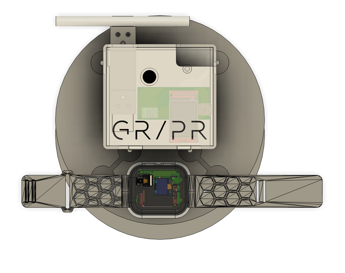

Table of Contents
Project Overview
- • Week Highlights
- • System Integration
- • System Integration Plan
- • Day 1: Design Integration
- • Day 2: Electrical & Mechanical Integration
- • Day 3: Fabrication Integration
- • Day 4: Subsystem Integration
- • Day 5: Full System Integration
- • Day 6: Final Project Masterpiece
- • 1 Minute Video and 1 Slide Summary
- • Design Files
- • Bill of Materials (MirrorAge System)
- • Critical Path Analysis
Development
Documentation
Week 14 System Integration
Final integration week focused on bringing all subsystems together, completing hardware fabrication, firmware integration, and documentation for the MirrorAge system presentation.
Week 14 Day-by-Day System Integration Plan

Theme of the Week
The act of bringing something to a conclusion or ending in a decisive manner. The ability to efficiently finish tasks and projects with a goal-oriented mindset.
Wednesday
- Publish system integration plan on website
- Update weekly assignment sections on final project page (weeks 10-13)
- Link final project design files
- Update reflections and learnings
- Update picture of prism holder
- Add final pictures to Slack canvases
- Create schematic between boards (wired and wireless) — updated system diagram on PPT-like page
- Start CAD model of system
- Place final order
- Boards: Combine OLED screen/accelerometer with pulse oximeter board in a new board (maybe upgrade to small TFT as minor)
- Boards: Speaker board with realtime amplifier and TFT (on the load cell fixed board)
- Band: Mold design
- Cases: 3D print mountable cases for the boards
- Integrate designs into final CAD
- Document design
- Finish CAD model of system
Thursday
- Milling boards
- Print mold and cast band
- Print cases
- Solder components on milled boards
- Connect boards with wired (and wireless connection codes)
- Mirror on screen (easy way with the film)
- Document fabrication
Friday
- Board level codes
- Server level codes
- Document codes
- Finish anything else
Saturday
- Demo integrated system
- Test integrated system
- Document testing and evaluation
- Review and complete documentation (list of questions)
- Make the video by collaging documentation
Sunday
- Fill up any gaps
- Prepare demo on tensegrity table
- Finalize 1-slide
- Work on minors
- If done, work on if there's time
Monday Morning
- Transport demo on tensegrity table
- Fill up any gaps
- Work on minors
Specific Tasks to Complete This Week
- CAD model of system
- Speaker board with realtime amplifier
- Combine screen/accelerometer with pulse oximeter board in a new board
- Mold and cast band
- Design and fabricate casing (print)
- Schematic between boards (wired and wireless) — updated system diagram on PPT-like page
- Serial connection between pulse oximeter and tiny blinking heart for BPM (BPM from IR, SpO2 from delta)
- Combine multiple boards on the same WiFi (switching tabs is easy way, board hosting the webpage querying and update or Python-based server somewhere where everything posting data, Raspberry Pi)
- Put+program everything together according to the above (with WiFi for now)
- Mirror on screen (easy way with the film)
- Document evaluations and costs (plus the rest of the list here: project presentation requirements)
- Summary slide and one-minute video for documentation
- Conception
- Construction
- Operation
- Program microphone/speaker
- Fix reaction time delay code
- Program LoRa connection
- Fix OLED plus WiFi issue
- Upgrade to TFT (SPI is very straightforward, design board with either SPI or OLED connection)
- Fix heart engraving to center
- Engrave K9 glass mirror if it arrives
- RD and IRD isolation slit (maybe wick and then cut)
- Do the calibration curve for the load cell
- Finish cardboard laser cutter origami big mirror frame
- Moving base of mirror
- Raspberry Pi Zero (or server host, do some research)
- Aim for 2.5 minutes because Neil will ask questions
- Generally no slides except for 1 open summary slide (have backup slides in case questions come up!)
Related: See the Development Timeline on the final project page for the overall project schedule.
Day 1: Design Integration
Initial system integration work focused on subsystem validation, CAD model consolidation, and design backbone acquisition for band integration.
Subsystem Validation
Conducted comprehensive testing of all subsystems to ensure proper functionality. Identified and resoldered any defective joints, verifying that each subsystem operates correctly before proceeding with full system integration.
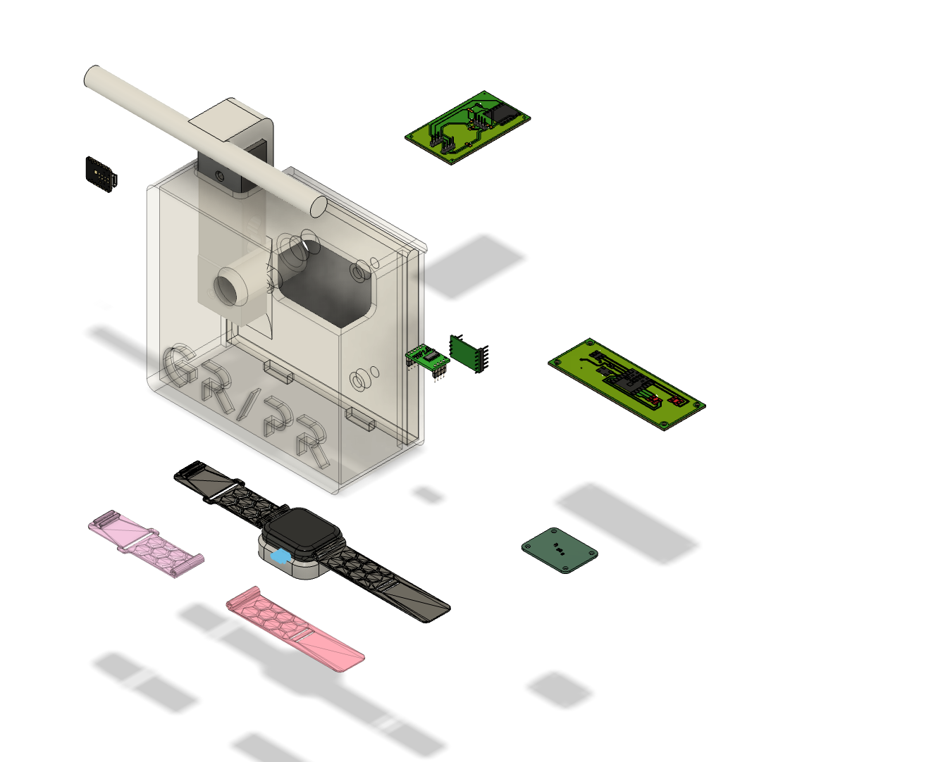
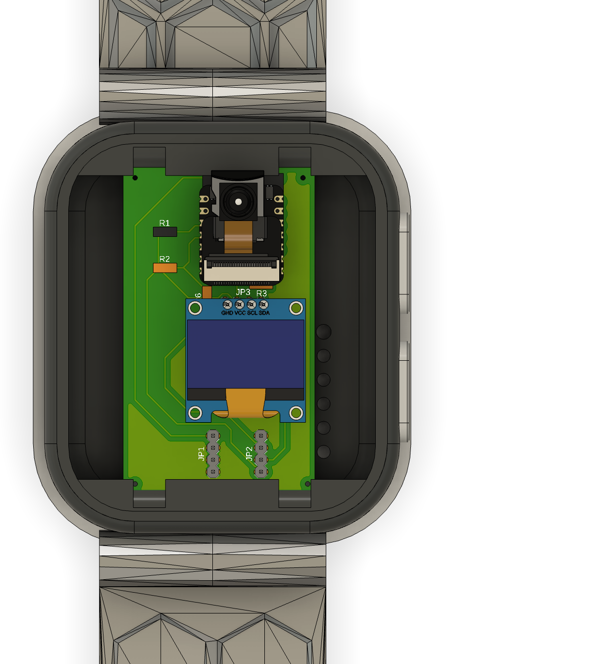
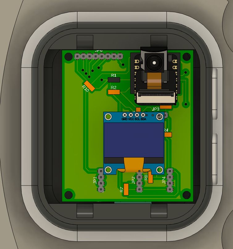
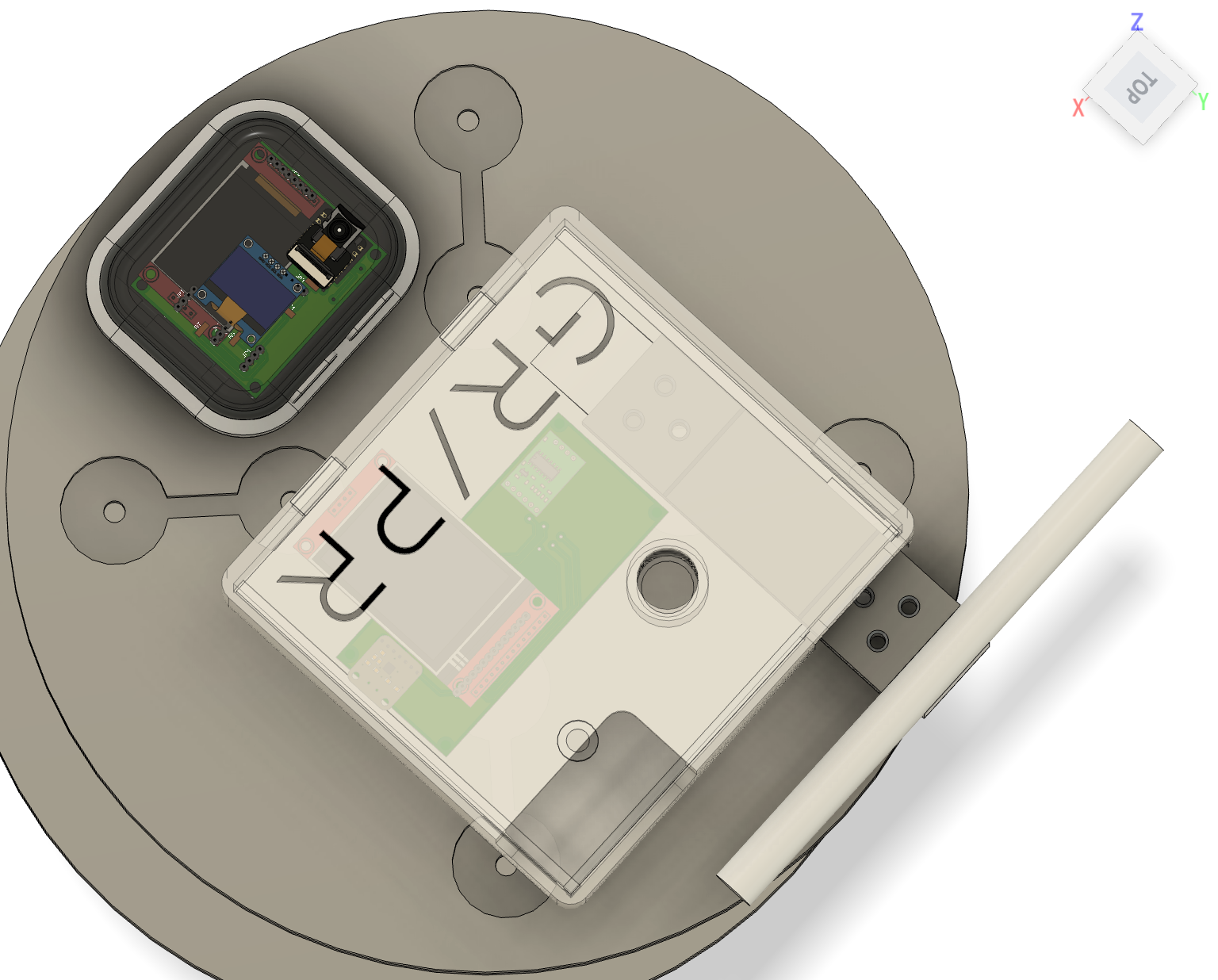
CAD Model Consolidation
Exported CAD models of all PCBs in the final design and imported them into a unified CAD assembly. This consolidated model provides a complete view of the system's mechanical integration and spatial relationships.
Band Design Backbone
Acquired CAD design files for Apple Watch form factor integration, enabling compatibility with existing band designs and standardized watch components. This provides a proven mechanical foundation for the wearable subsystem.
Next Steps
Resuming the daily schedule tomorrow with parallel work streams prioritized according to the critical path. Tasks that cannot be completed during scheduled days will be shifted to buffer days on Saturday and Sunday to maintain project momentum.
Day 2: Electrical and Mechanical Integration
Physical integration of subsystems into the complete demo table assembly, including mechanical component fabrication and electrical board consolidation.
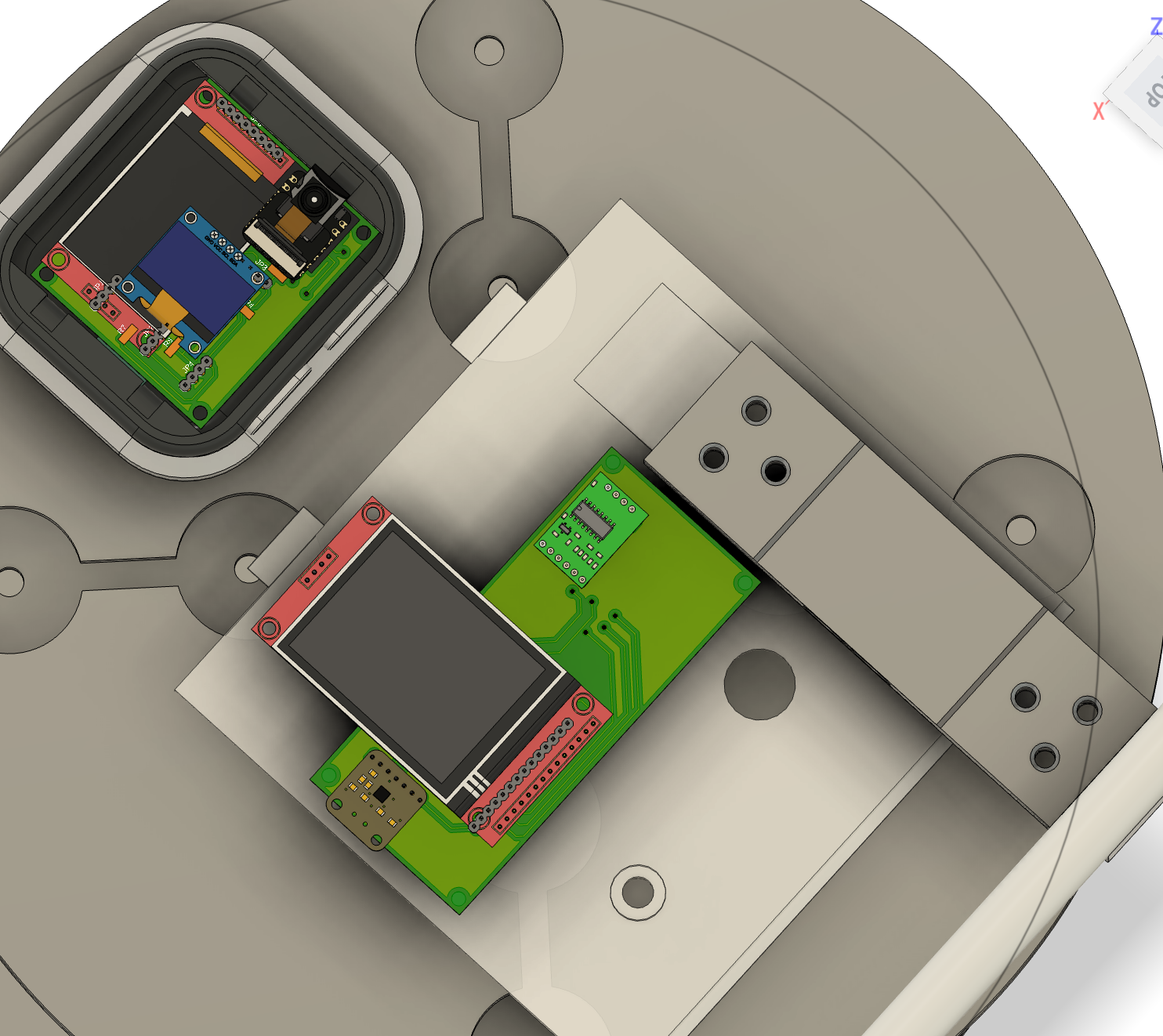
2.1 Mechanical Integration
Mechanical design integration now includes the complete demo table with precise placement of the MirrorAge handgrip subsystem and the aging clock subsystem. The integrated assembly provides a unified platform for system demonstration and testing.
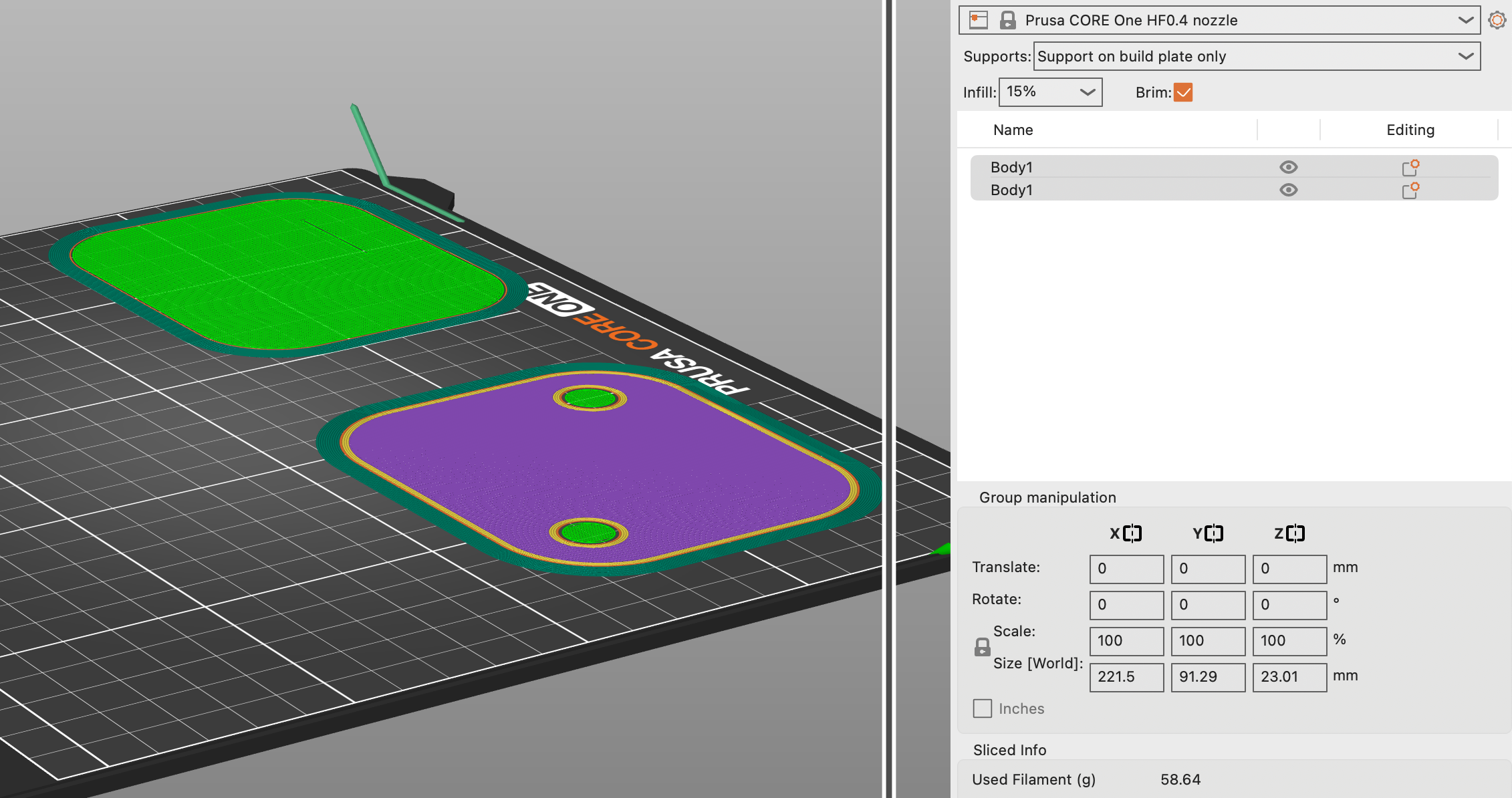
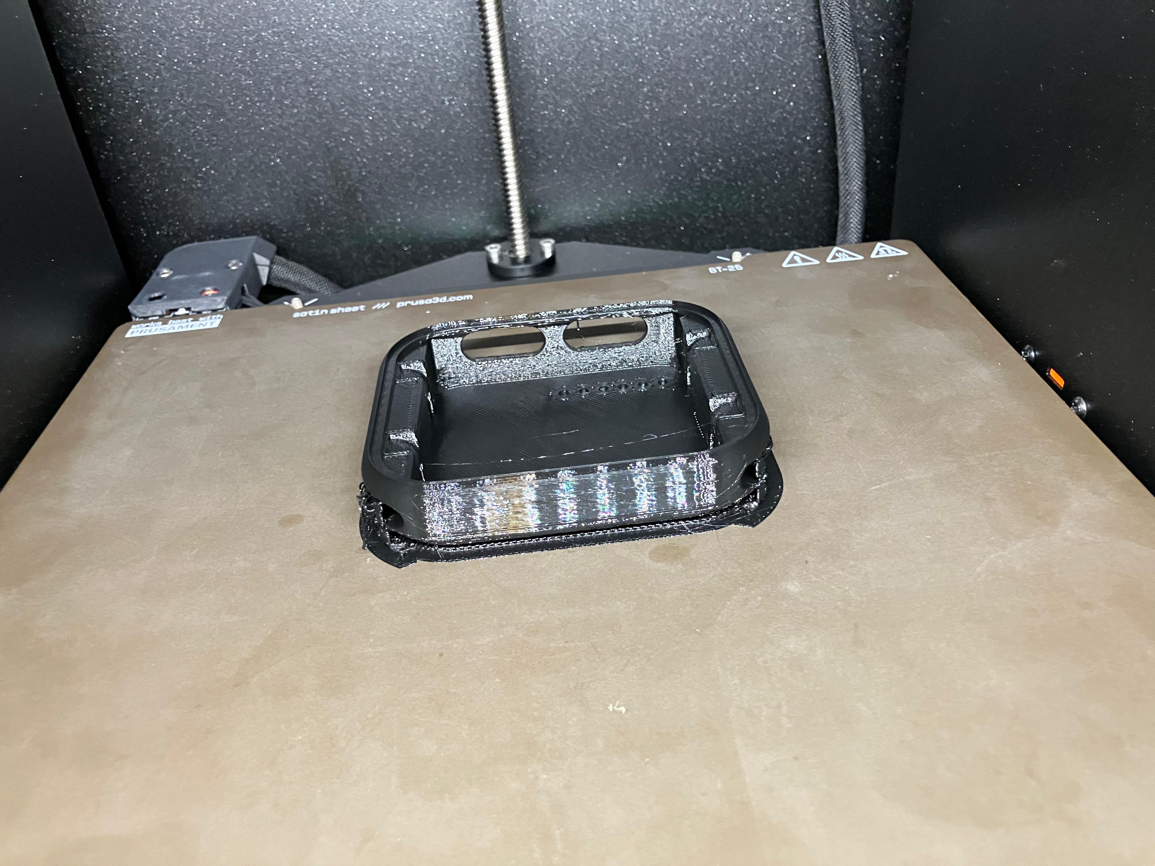
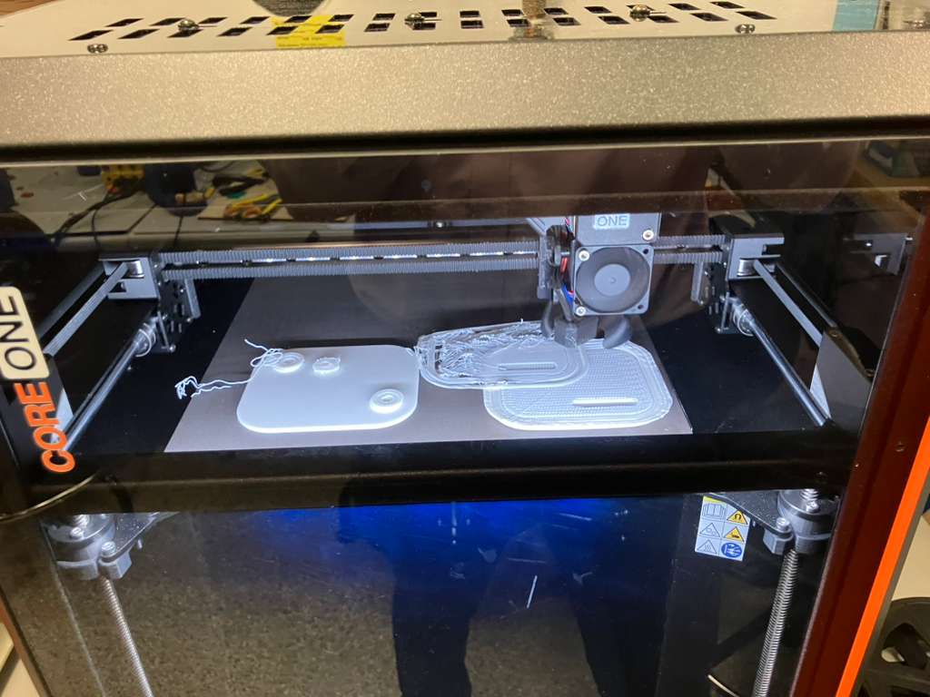
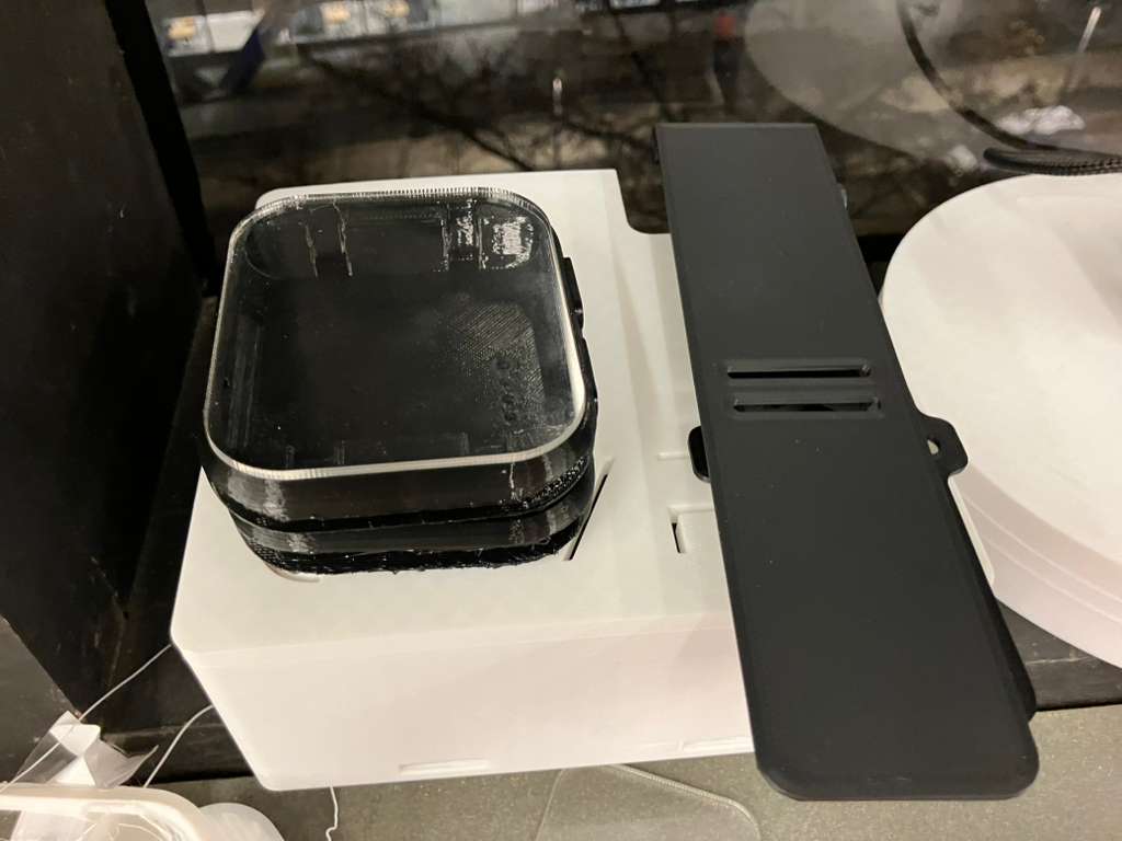
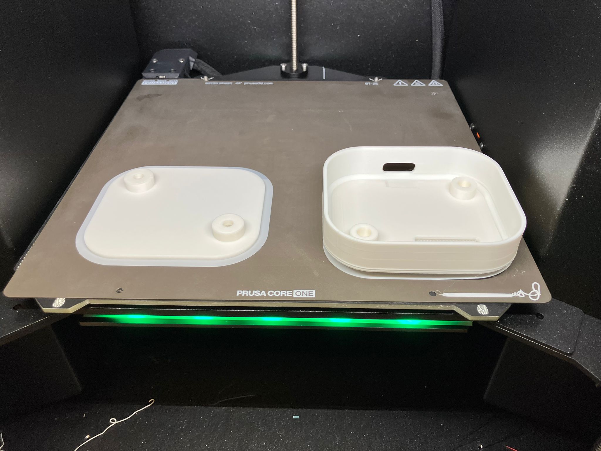
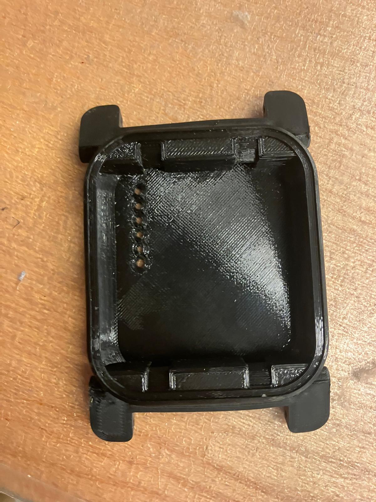
3D Additive Manufacturing
All 3D additive mechanical components were printed for rapid iterative development. The fabrication process required specific print settings and support strategies for different components:
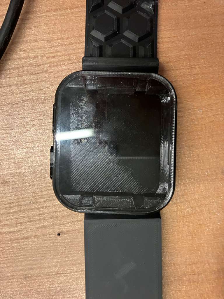
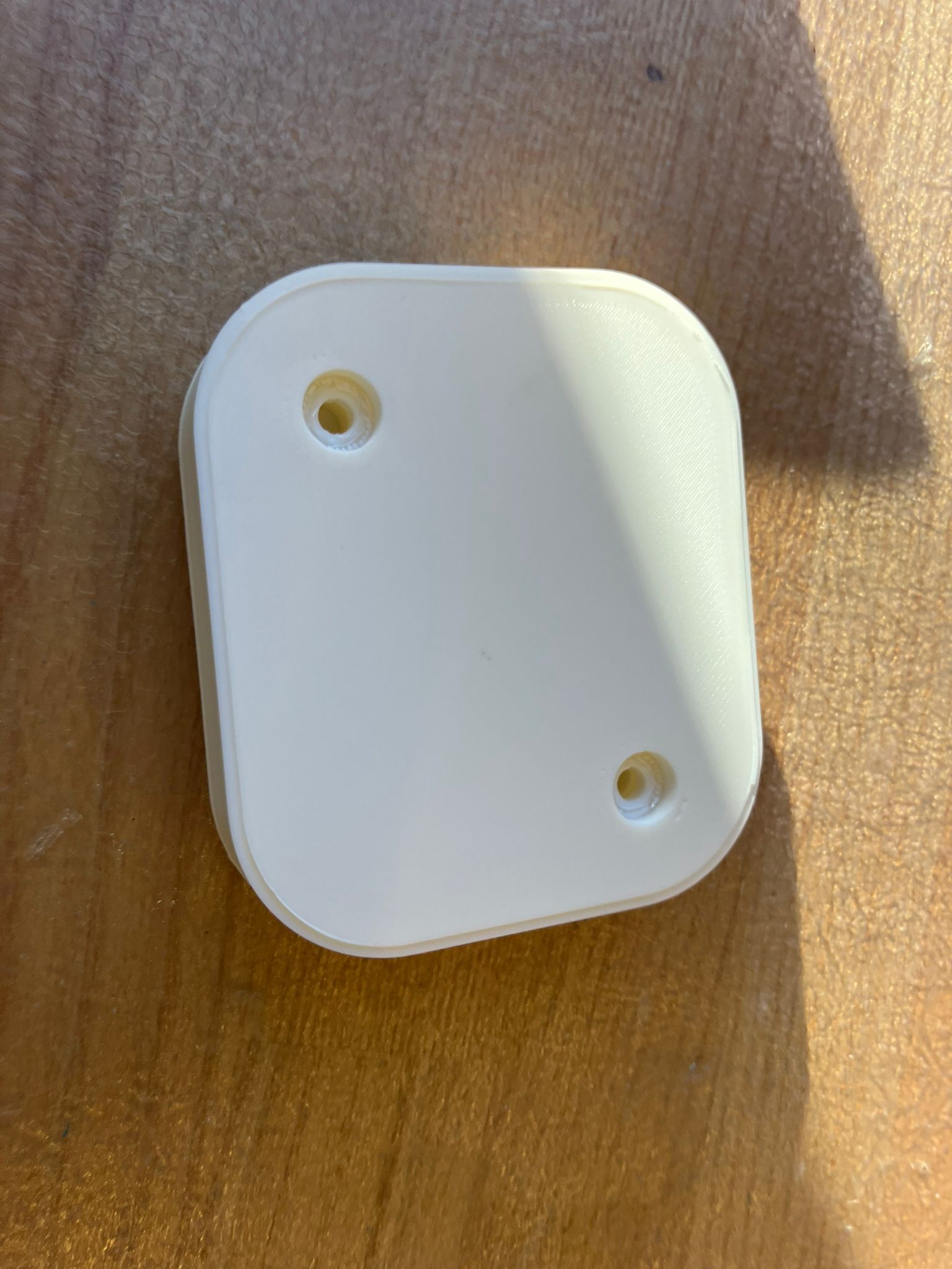
The 3D printed watch casing and band designs were adapted from the open-source MutantW V2 ESP32-S3 smartwatch and scaled 2:1 for this project. Reference designs and build details are available in the MutantW V2 repository, Instructables guide, and Arduino community discussion.
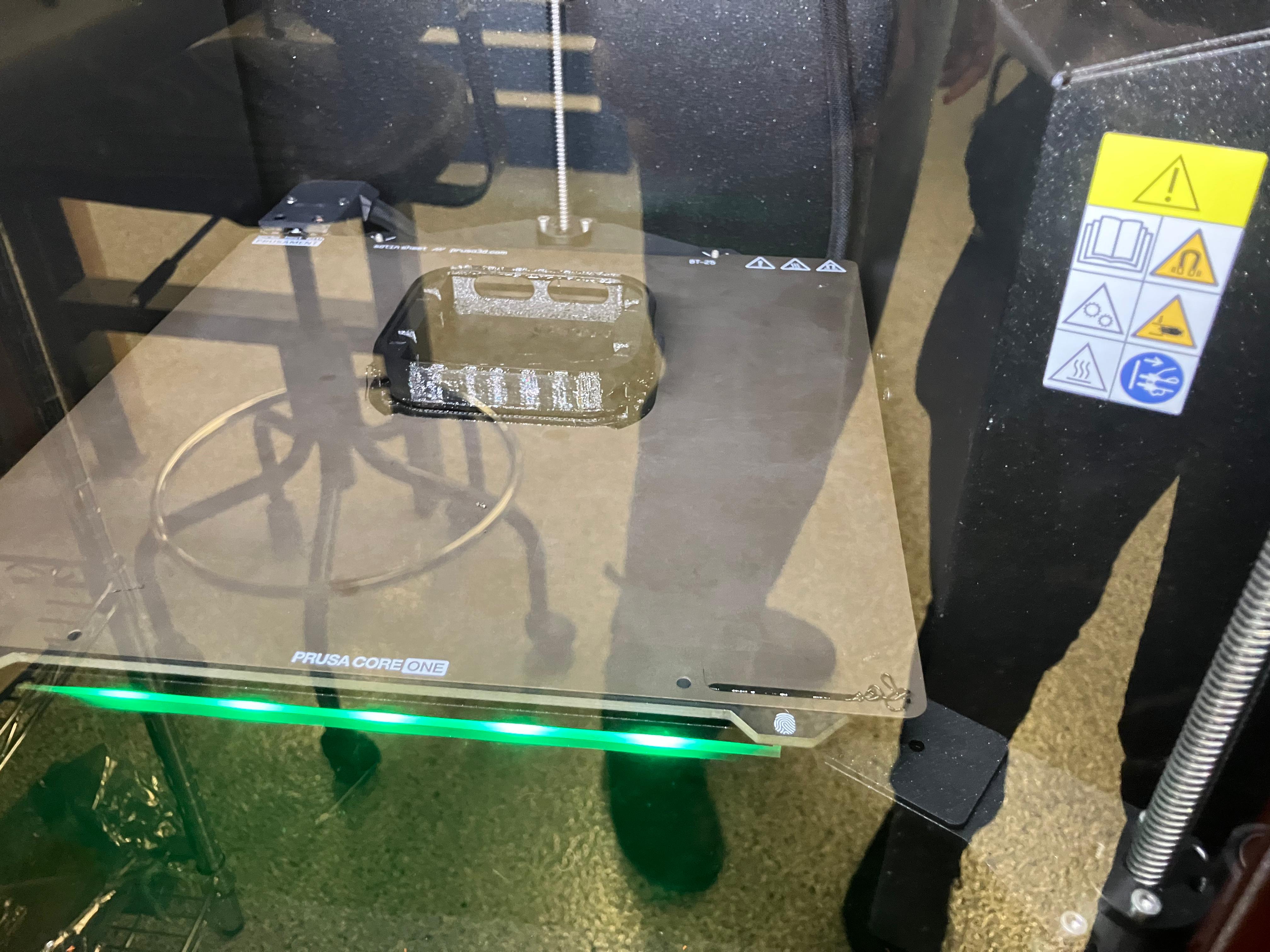
- Casing: Required organic support structures for complex overhangs
- Dock: Required brim adhesion to prevent warping during printing
- Bands: Printed using TPU (Thermoplastic Polyurethane) material for flexibility (will spiral into molding and casting in future iterations)
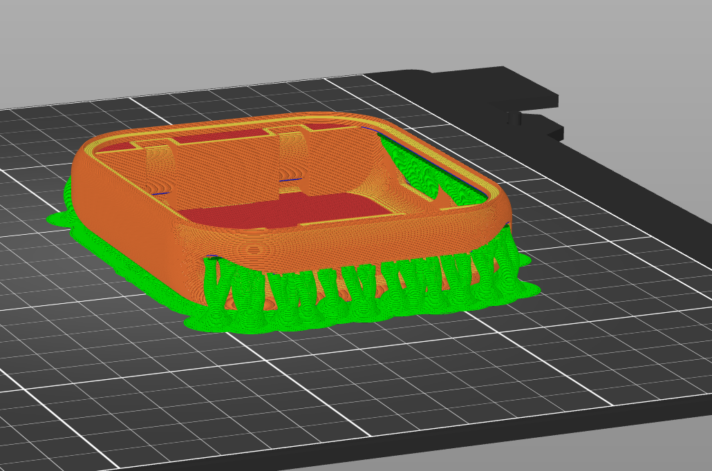
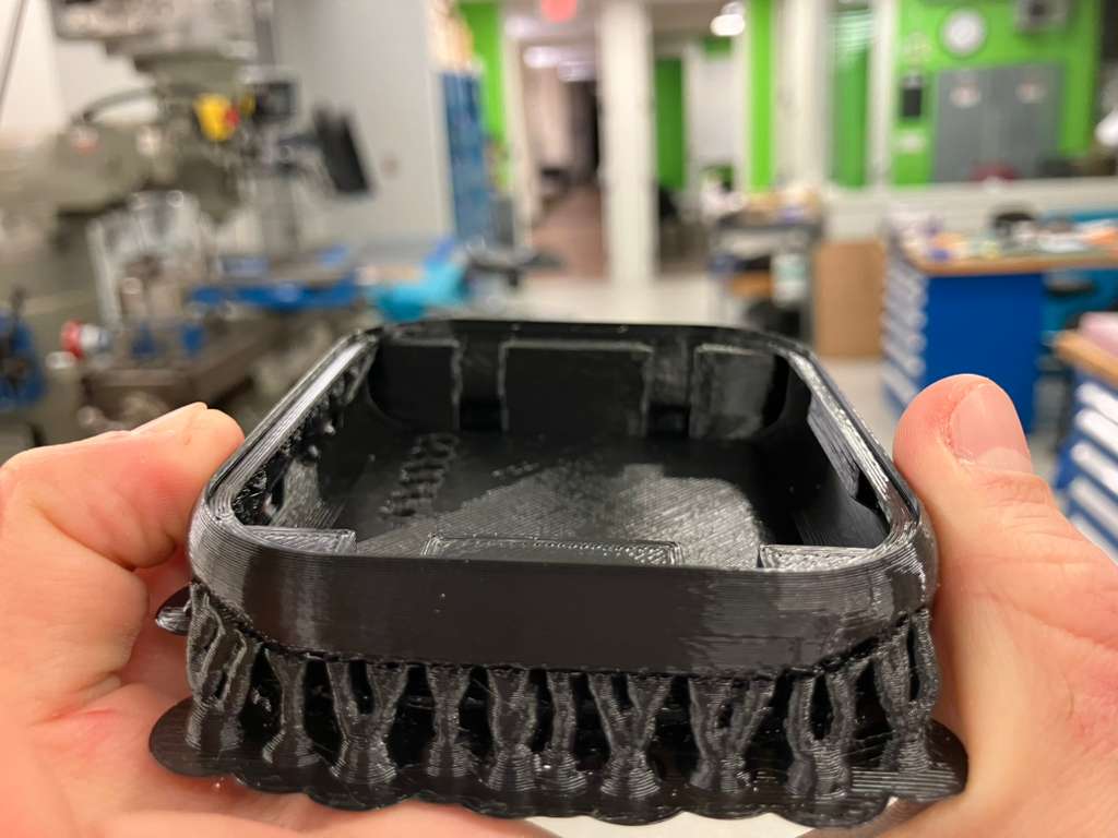

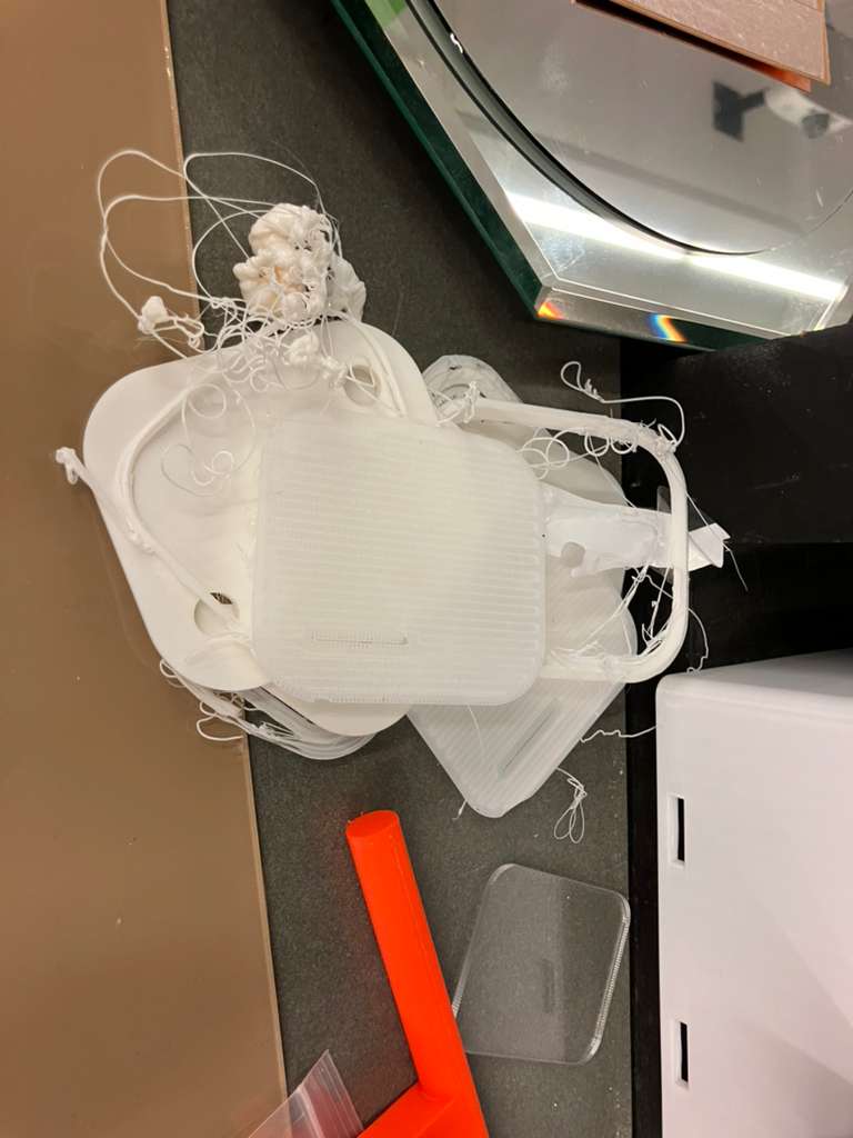
Print Failures and Iteration
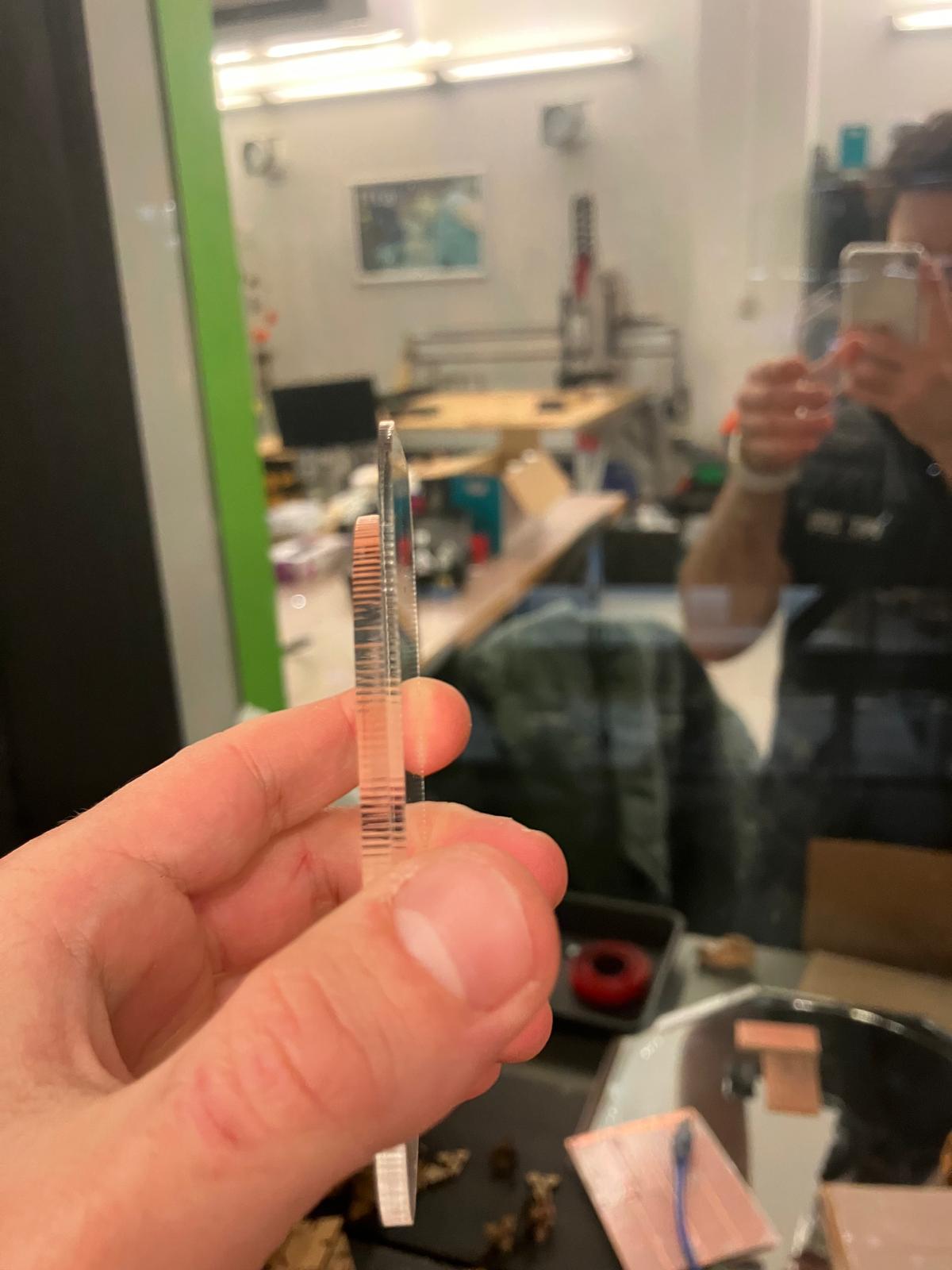
2D Subtractive Manufacturing
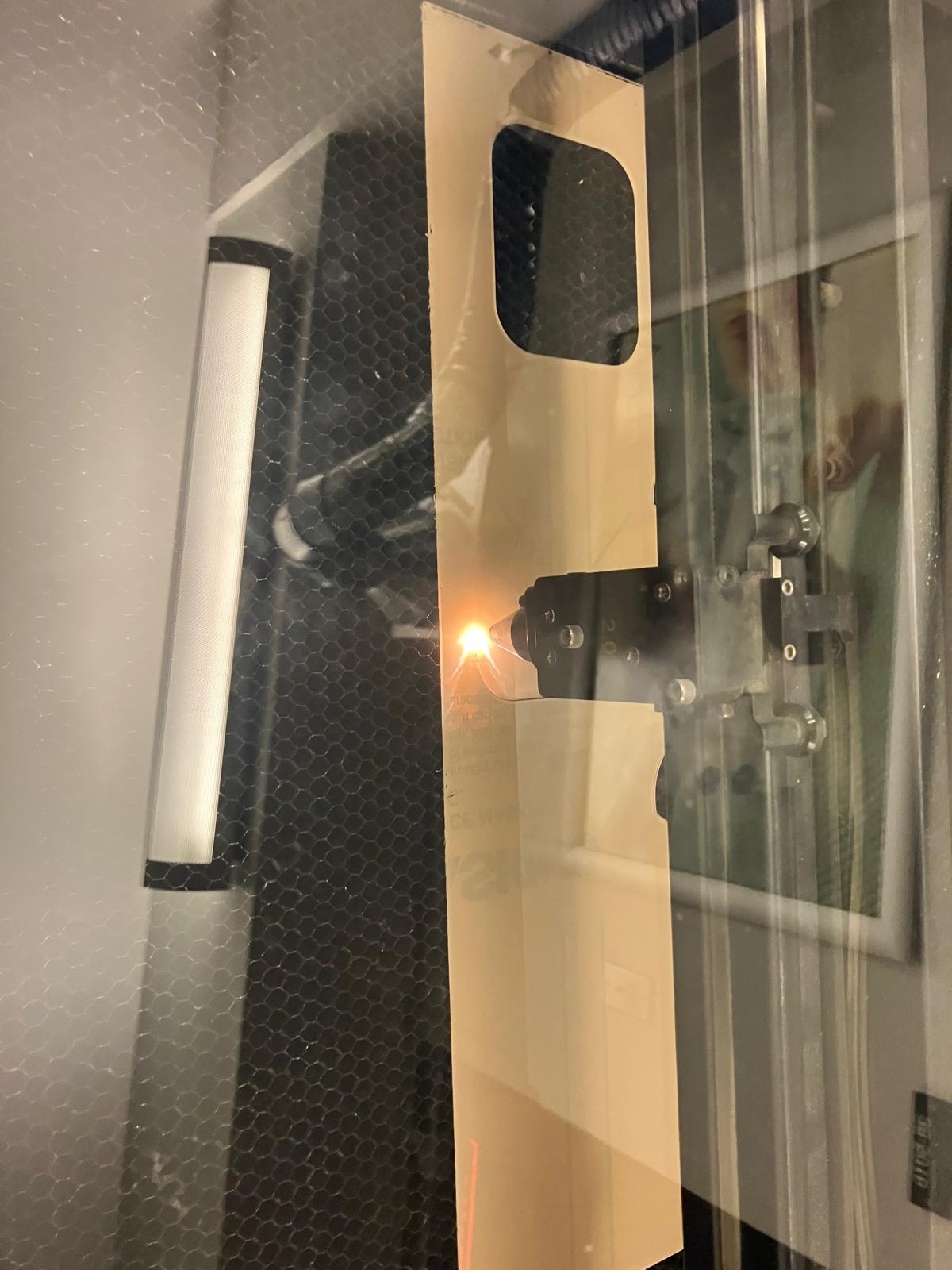
The first 2D subtractive mechanical component was debugged and fabricated. The display face component required exporting a DXF of the full face to laser cut an acrylic display that fits the casing precisely. The original display part face was too small because it was filleted, so the edges of the aging clock body were traced and exported for accurate laser cutting.
2.2 Electrical Integration Methods in Spiral Development
Electrical design integration combines multiple subsystems into unified board designs, with progressive upgrades incorporating TFT displays for enhanced visual feedback. The integration follows a spiral development approach, starting with base designs and iteratively adding features like TFT displays as design constraints are validated.
Board Design Evolution
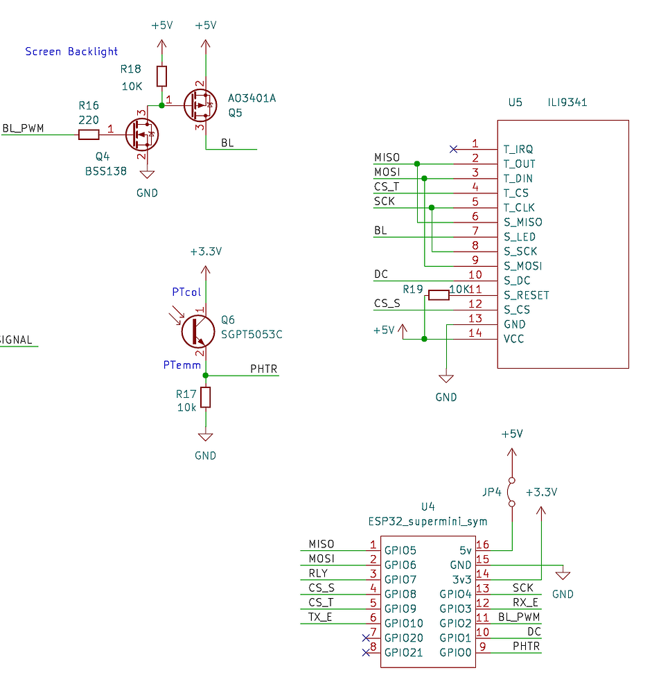
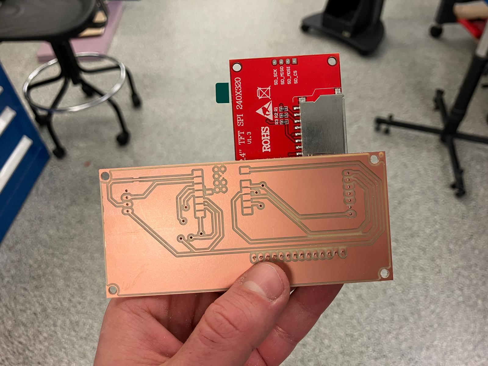
TFT Display Integration
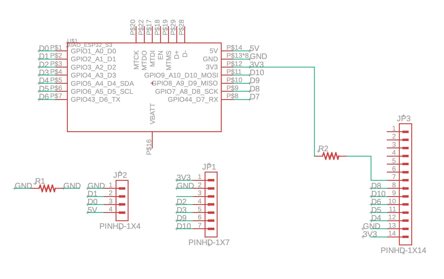
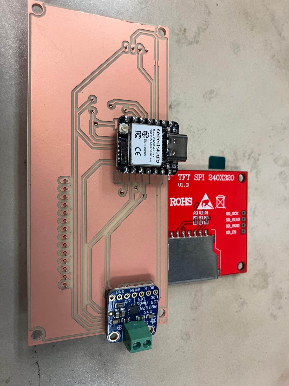
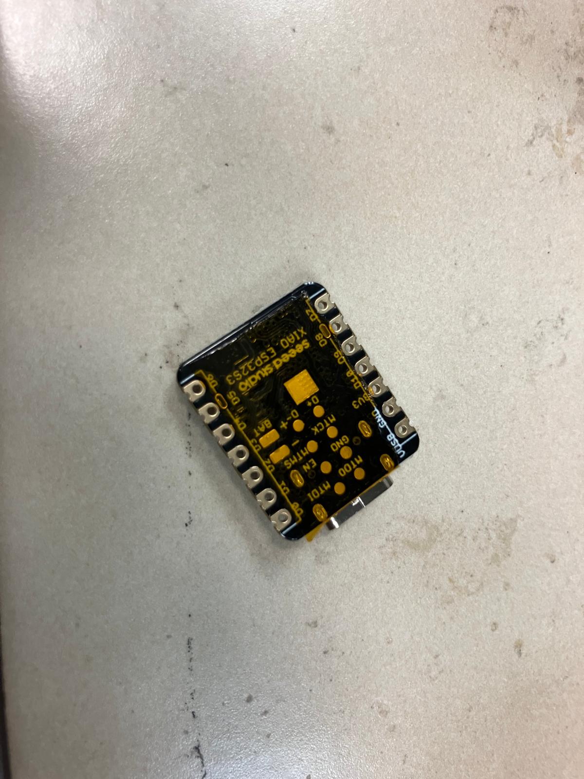
Both the aging clock watch board and the MirrorAge load cell-speaker board have been upgraded to include TFT displays for enhanced visual feedback. The displays use SPI communication for straightforward integration with the ESP32-S3 XIAO microcontroller.
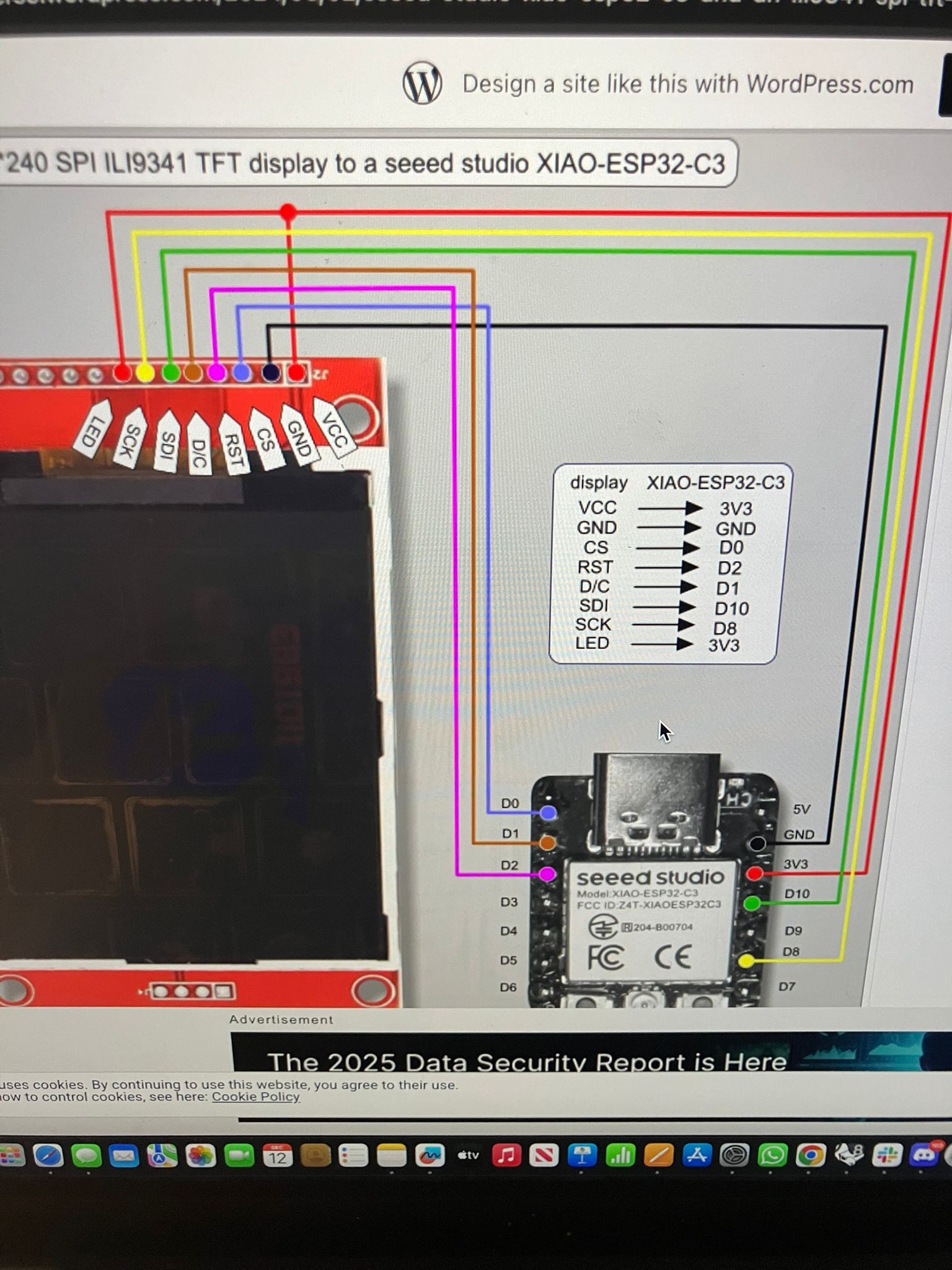
Based on the Seeed Studio XIAO ESP32-C3 ILI9341 wiring guide, adapted for ESP32-S3 XIAO:
| TFT Pin | ESP32-S3 XIAO Pin |
|---|---|
| VCC | 3V3 or 5V |
| GND | GND |
| CS | D0 |
| RST | D2 |
| DC/RS | D1 |
| SDI (MOSI) | D10 |
| SCK | D8 |
| LED (Backlight) | 3V3 |
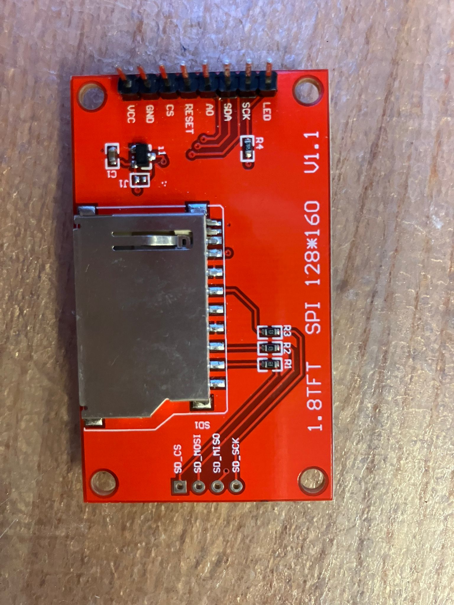
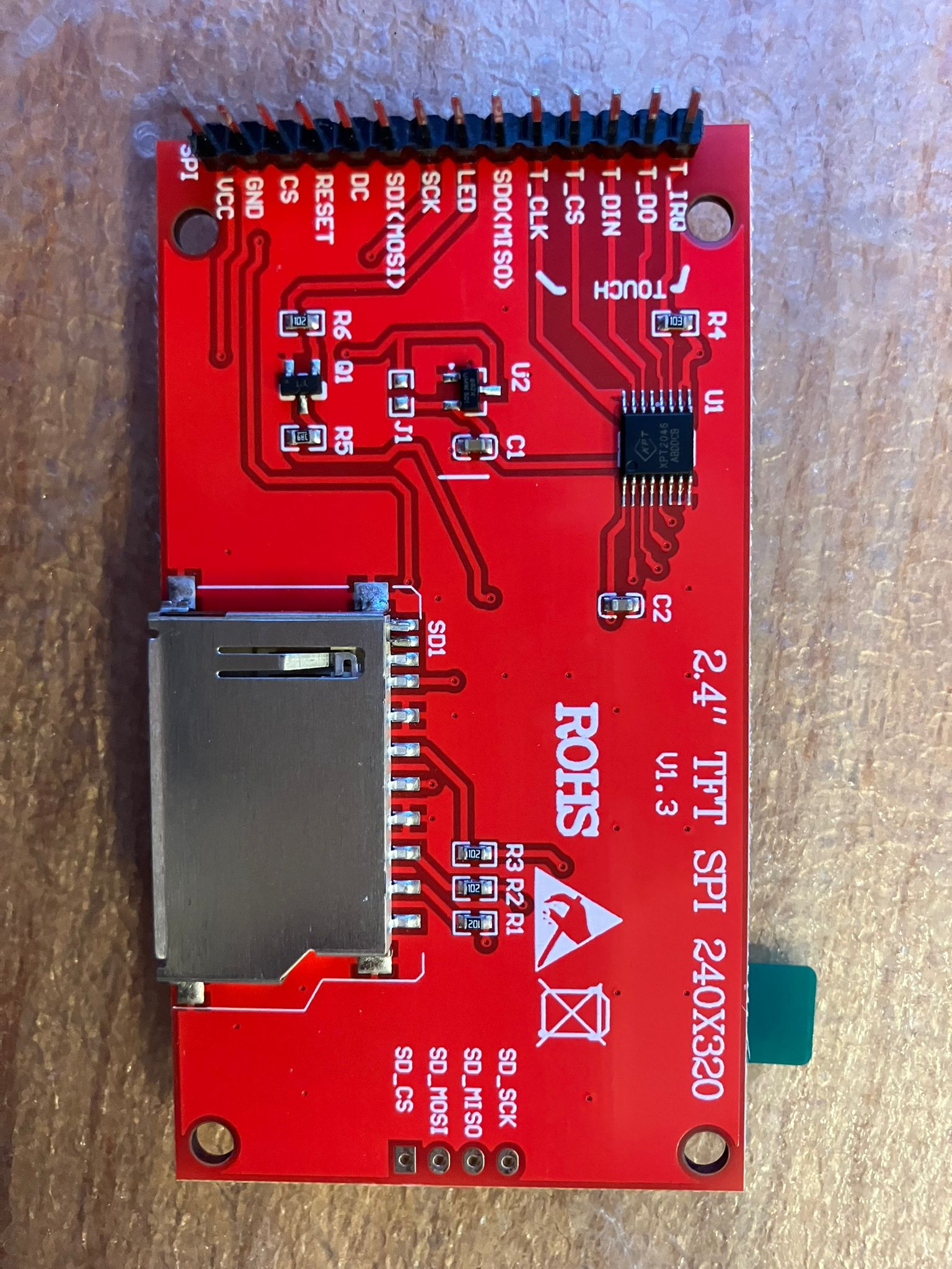
Note: For both 1.8" and 2.4" TFT displays, the LED backlight pin connects to 3V3. Additional references: 1.8" TFT Guide, 2.8" ILI9341 Guide, ESP32-S3 ILI9341 Guide
For future iterations incorporating touchscreen functionality, the ILI9341 TFT with integrated touch controller requires additional pin connections. The touch controller shares the SPI bus with the TFT display and uses a separate chip select pin.
| Touch Pin | ESP32 XIAO Pin |
|---|---|
| T_CLK | SCK (GPIO8/D8) |
| T_CS | GPIO21/D21 |
| T_DIN | MOSI (GPIO10/D10) |
| T_DO | MISO (GPIO9/D9) |
Important Notes:
- The TFT reset pin can be pulled to 3V3 via a 10kΩ resistor (not 5V as sometimes shown in diagrams)
- The touch controller uses the same SPI bus as the TFT display, requiring a modified XPT2046_Touchscreen library with reduced SPI clock speed
- MISO pin (GPIO9) enters bootloading mode after reset—ensure proper initialization sequence
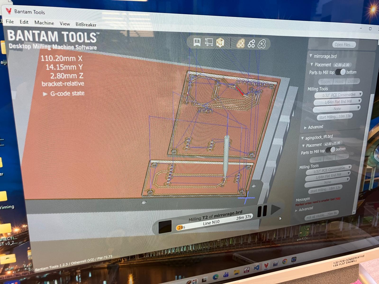
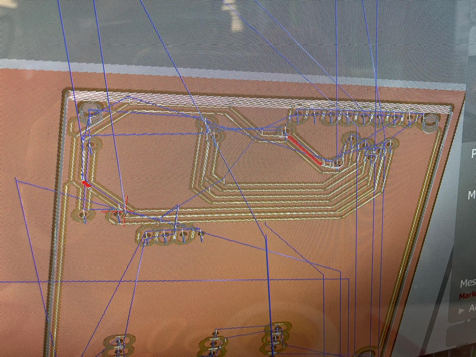
- Always verify front and back of PCB designs in Bantam Tools software before milling to avoid trace clearance issues
Reference Resources:
- ESP32-C3 and ILI9341 Touchscreen Wiring (Primary reference for pinout mapping)
- XIAO ESP32 MISO Pin Considerations
- ESP32C3 Thermal Imaging Camera with TFT Display (Example project with similar integration)
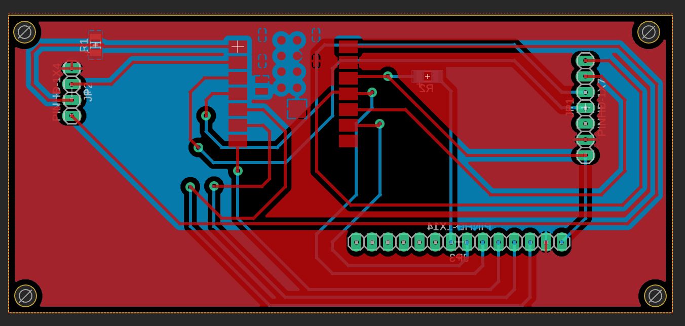
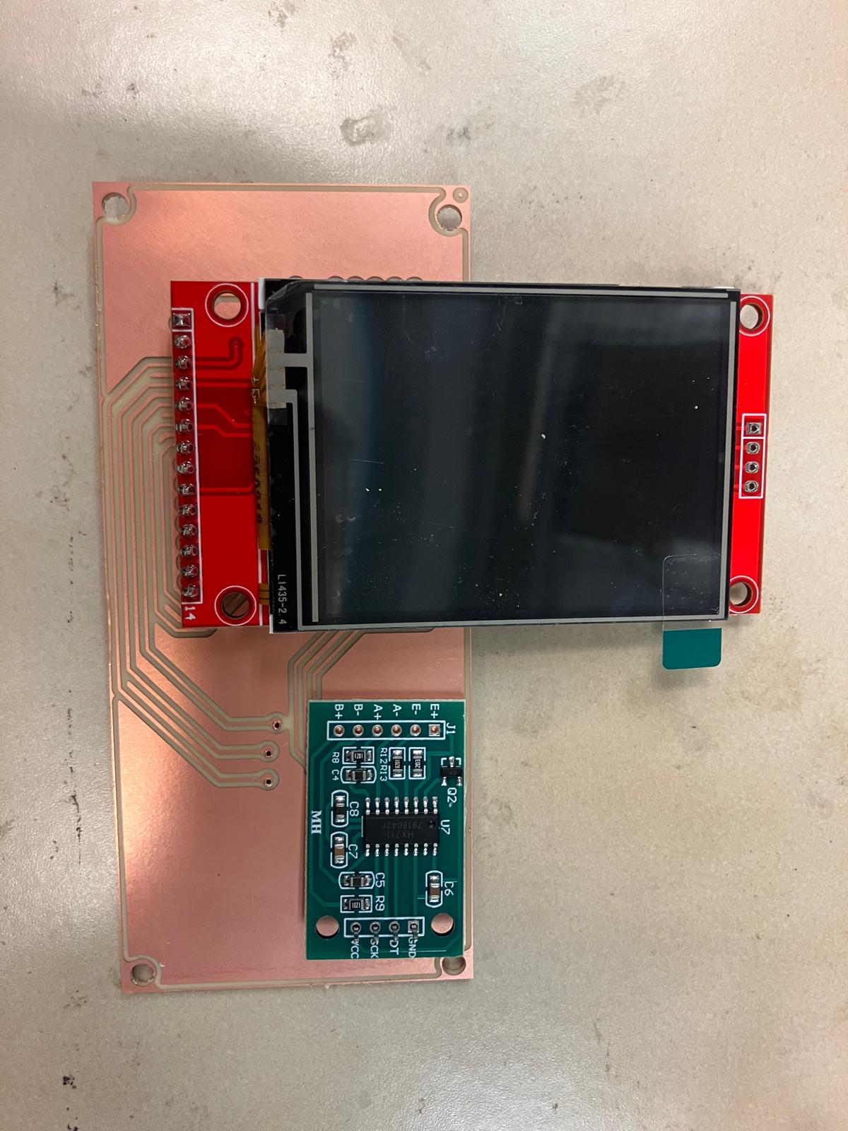
MirrorAge Amplifier Board Design
The MirrorAge amplifier board integrates a real-time audio amplifier with load cell interface and TFT display. The base design includes the amplifier circuit and HX711 load cell interface, with an upgraded version adding the 2.4" ILI9341 TFT display.
1.8" TFT LCD: ST7735 controller, 128×160 pixels. CAD model reference: GrabCAD ST7735 Model
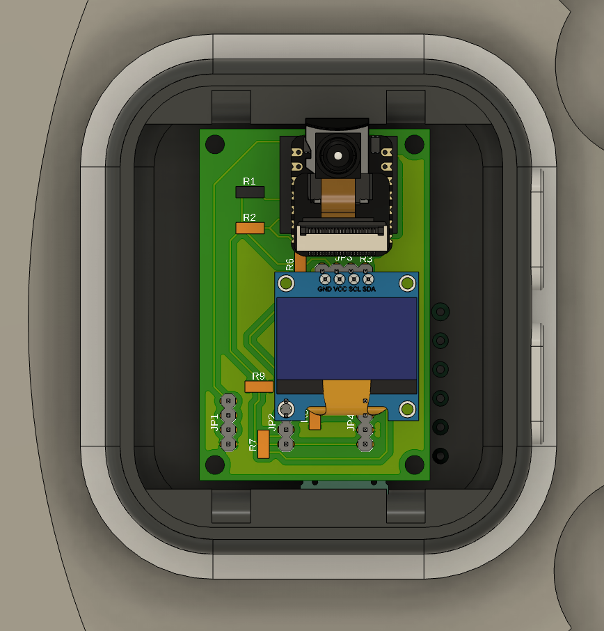
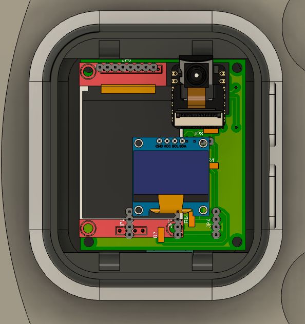
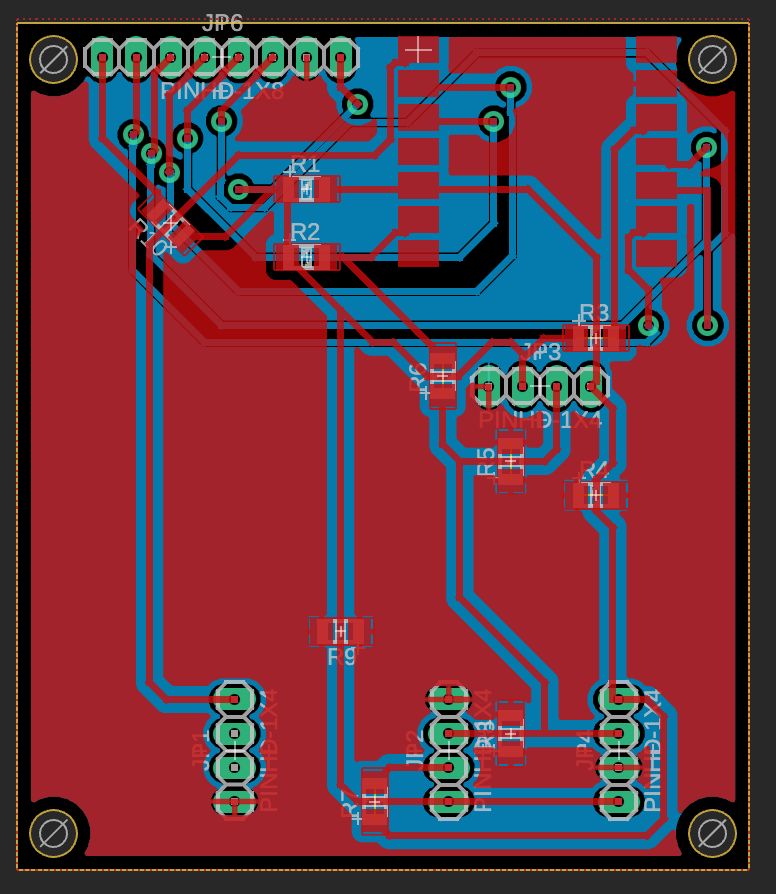
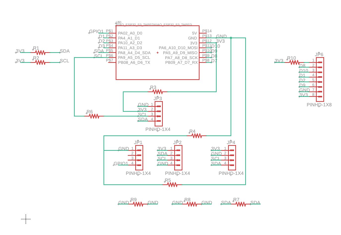
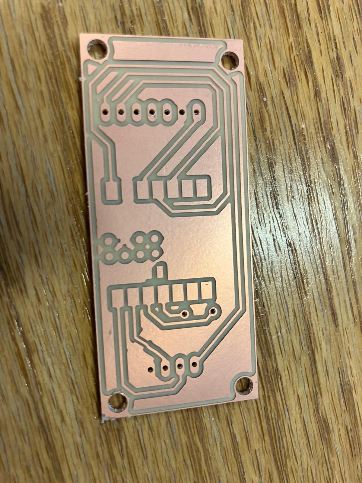
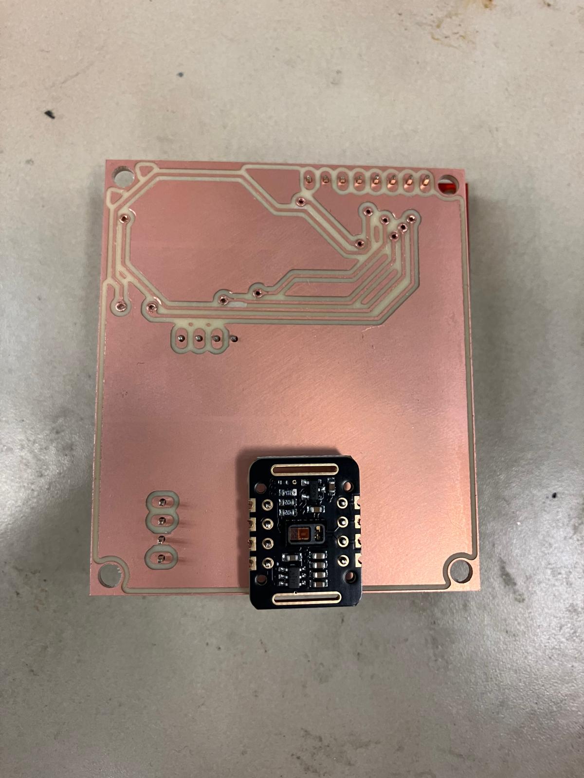
Aging Clock Watch Board Design
The aging clock watch board combines pulse oximeter sensors, accelerometer, and camera functionality. The base design uses an OLED display, with an upgraded version incorporating a 1.8" ST7735 TFT display for enhanced visual feedback.
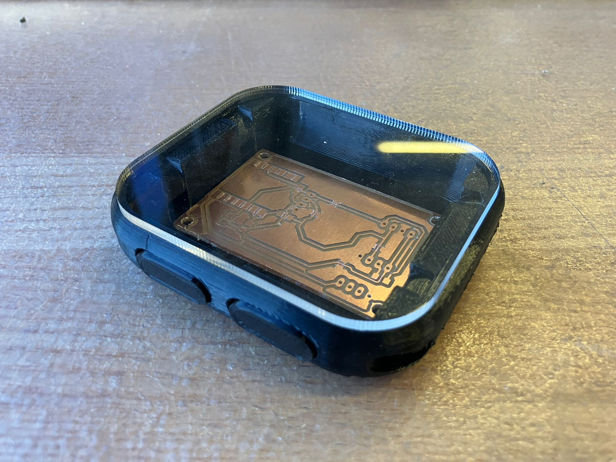
Board Fabrication and Integration
The first version of the aging clock board was milled. The initial board did not fit the casing, requiring either casing adjustment and reprinting, or milling a new miniaturized board with shrunken electronics. Both approaches are being evaluated. The MirrorAge board design has been completed for both base and TFT-integrated versions, ready for milling and testing.

Day 3: Fabrication Integration
Comprehensive fabrication integration work combining 2D laser cutting, 3D printing, and PCB milling to create fully integrated subsystems ready for assembly and testing.
2.1 2D Fabrication: Laser Cutting
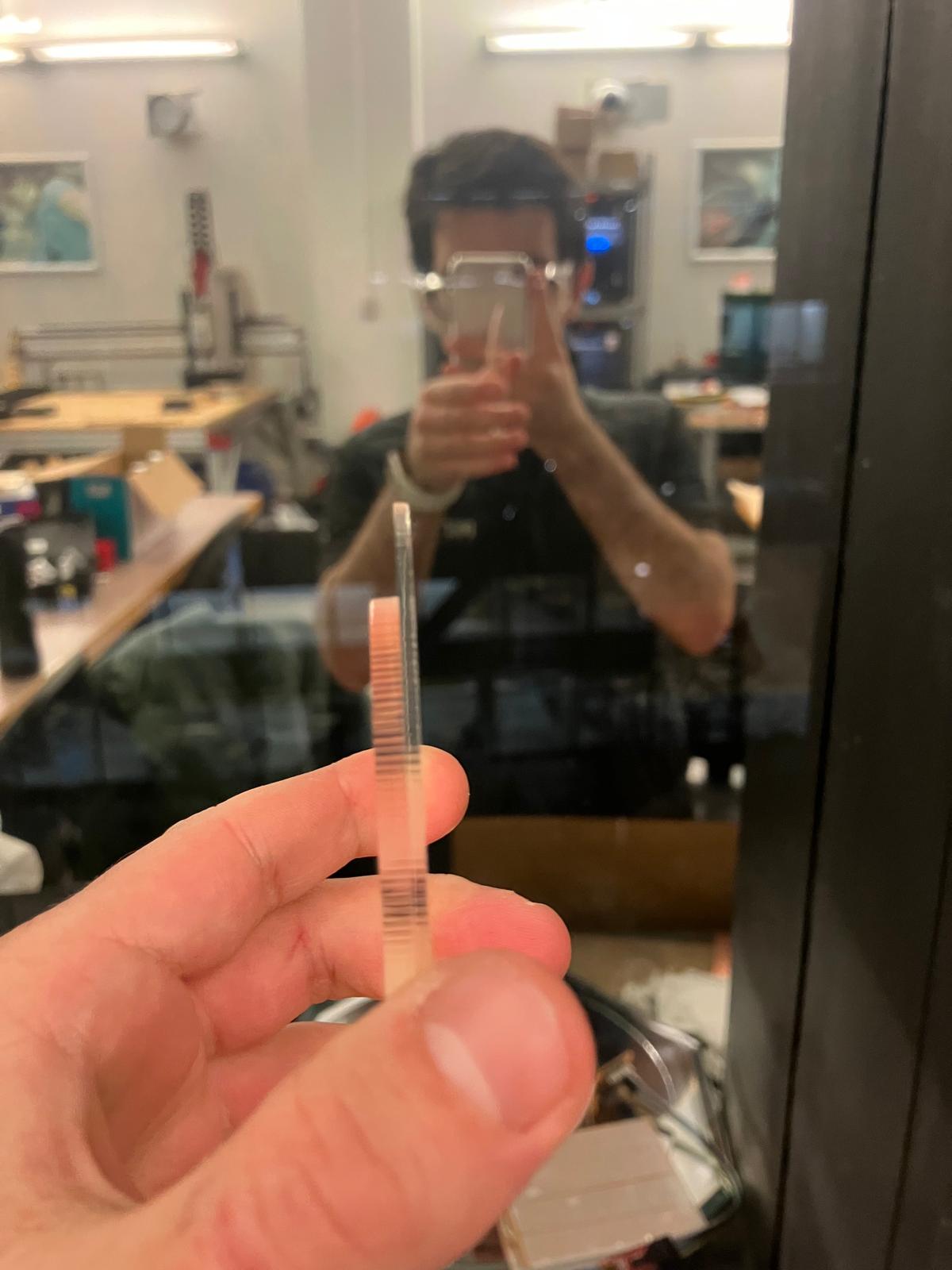
The laser-cut acrylic display component was updated in Day 2 and successfully integrated into the watch assembly. The acrylic display provides a clear protective face for the aging clock watch, precisely fitted to the casing dimensions.
The integrated watch assembly demonstrates successful integration of 2D subtractive manufacturing with 3D printed components, creating a cohesive mechanical structure for the wearable subsystem.
2.2 3D Printing: Rigid and Flexible Components
All 3D printed components were fabricated using both rigid and flexible materials. The bands were printed using TPU (Thermoplastic Polyurethane) for flexibility, while rigid components used standard PLA/PETG materials. Additional print details and configuration requirements are documented in Day 2.
The case should also be printed from TPU to improve interlock part fit. The spring-loaded interlock mechanism enables secure band closure while maintaining flexibility for comfortable wear.


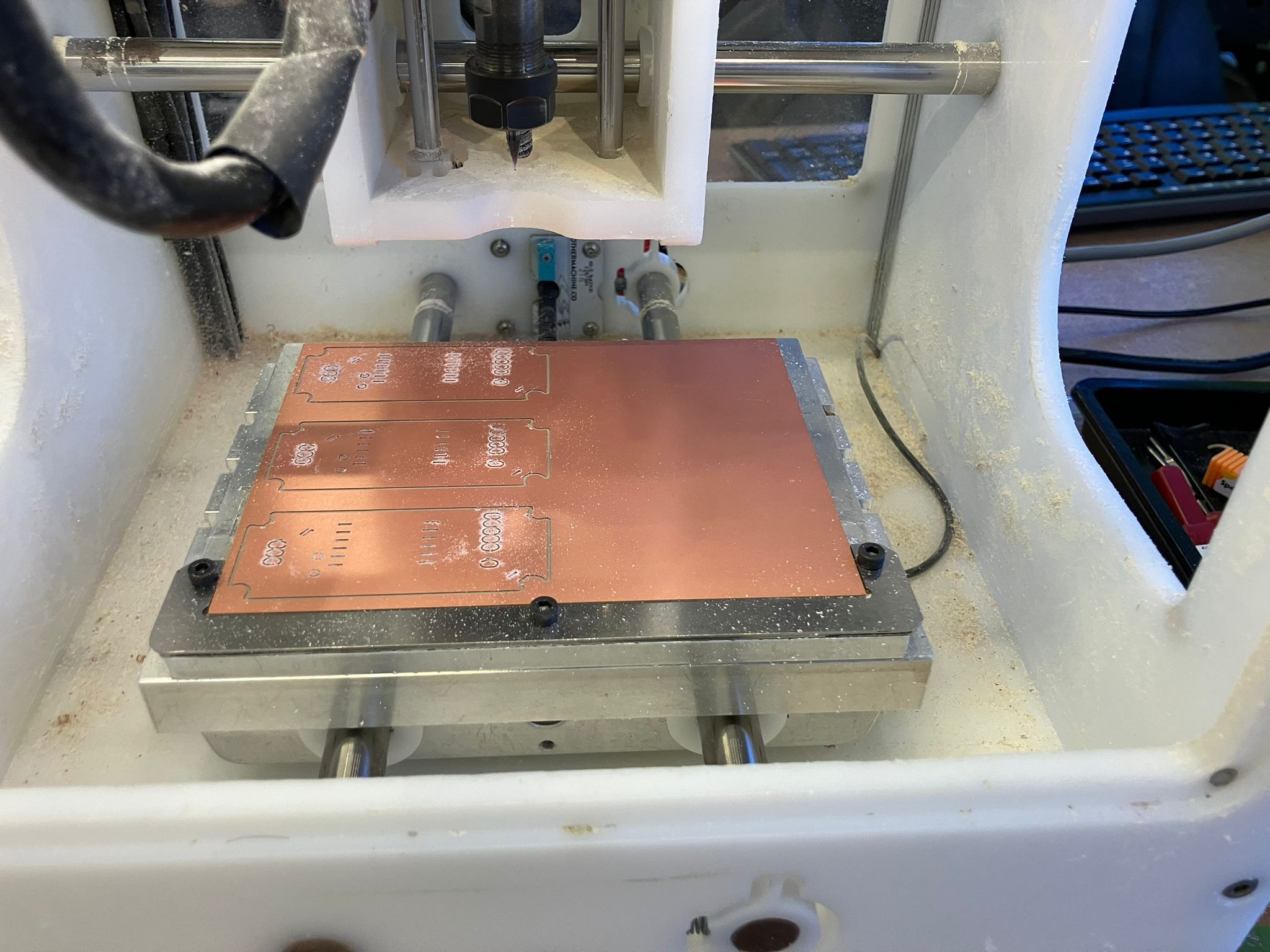
2.3 Milling: Single and Double-Sided Boards
Aging Clock Watch Board
The aging clock watch board was successfully milled. The base design with OLED display worked correctly, and the design has been upgraded to include a TFT display. The new TFT-integrated design will be milled and tested alongside the base OLED version to validate both display options.

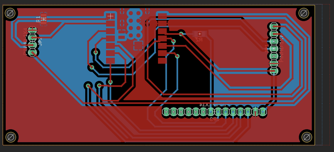
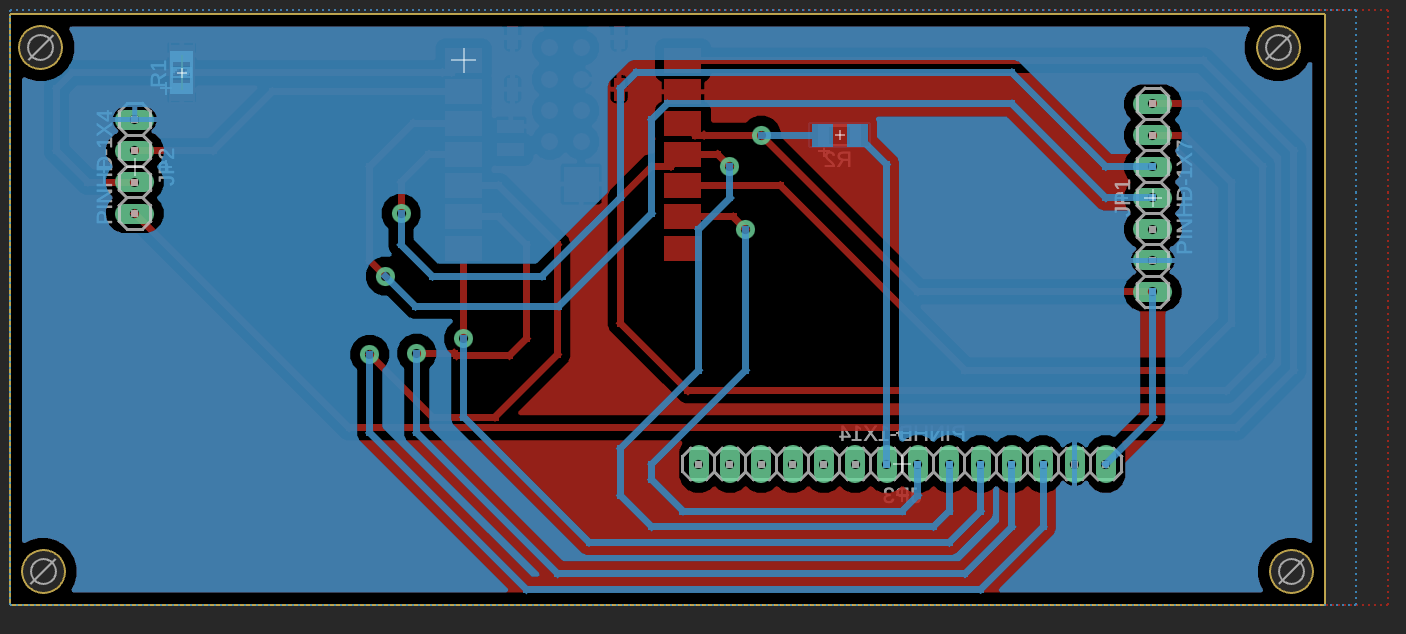
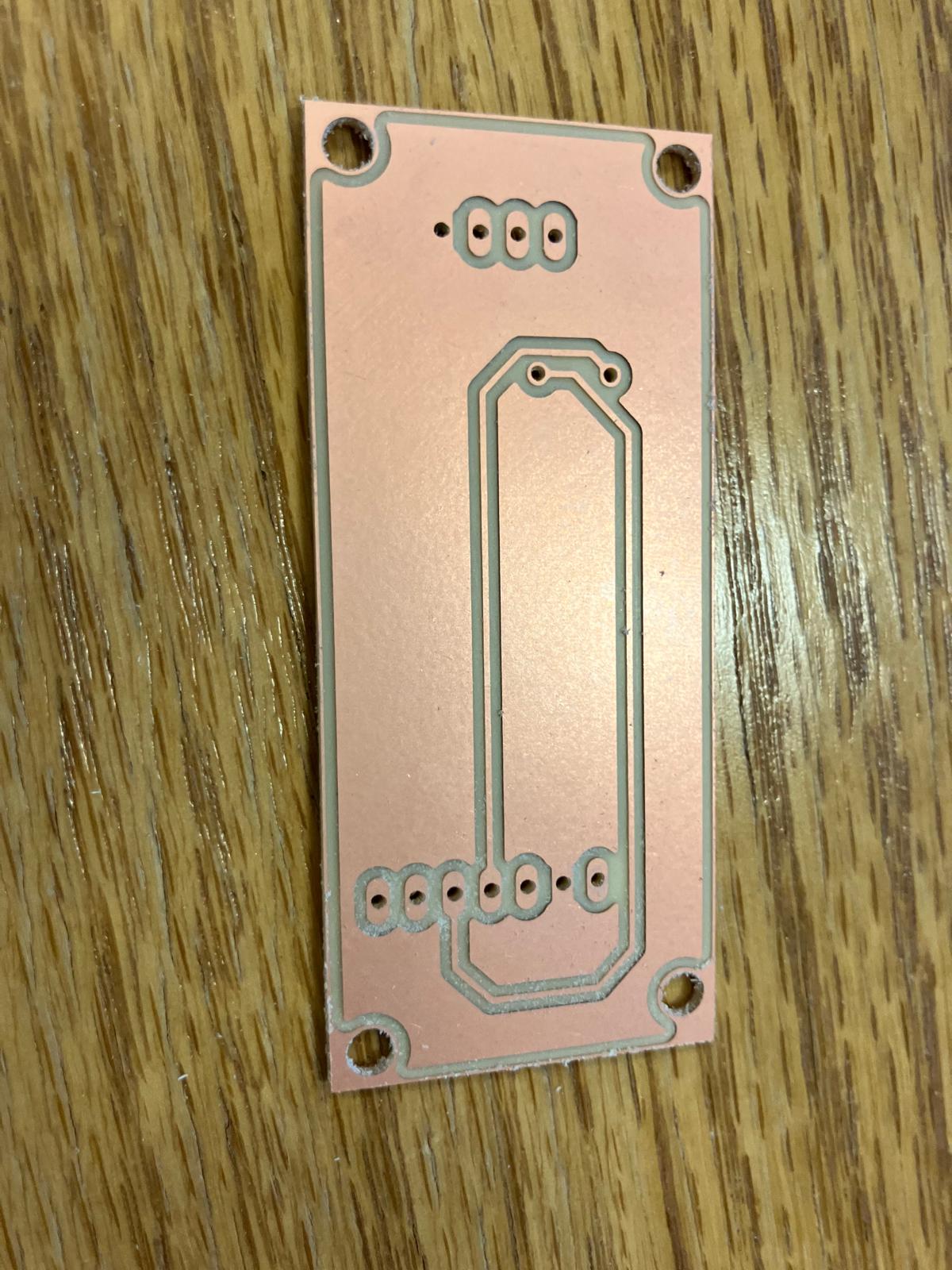
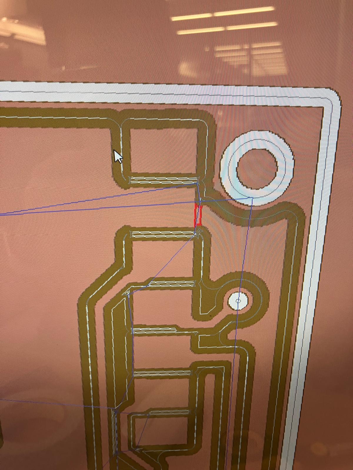
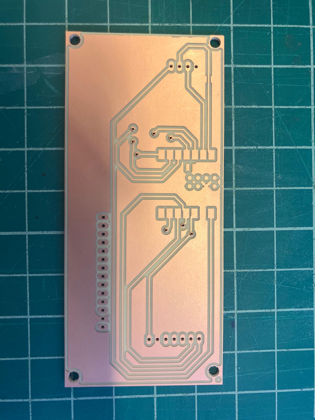
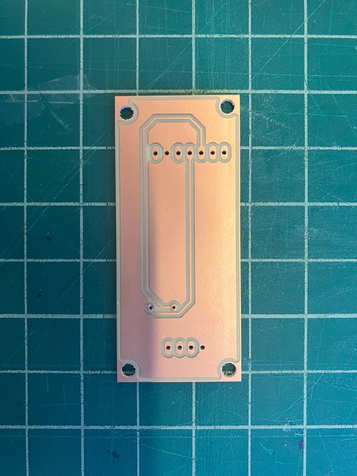
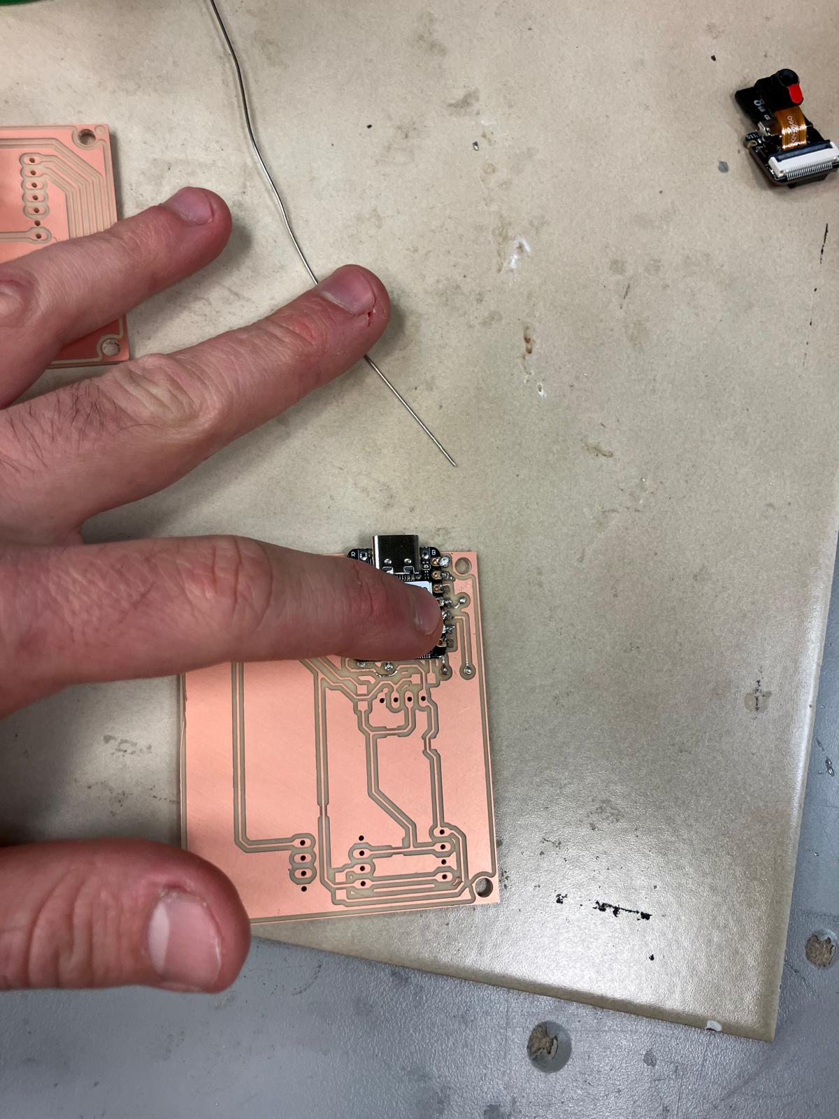
MirrorAge Amplifier Board
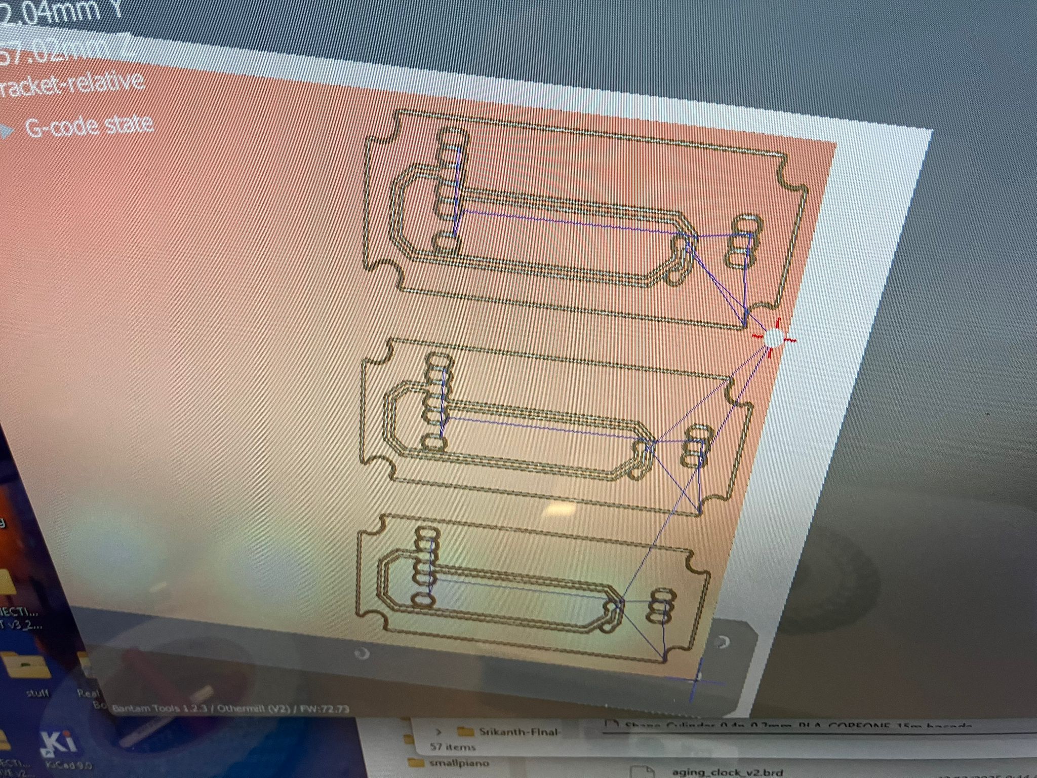
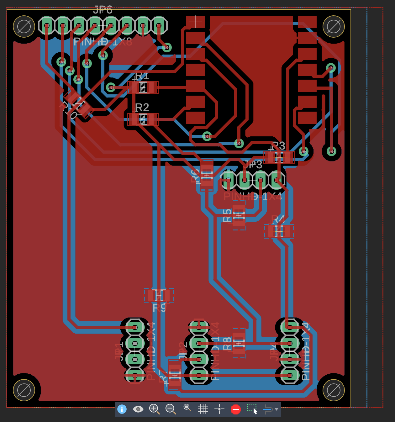
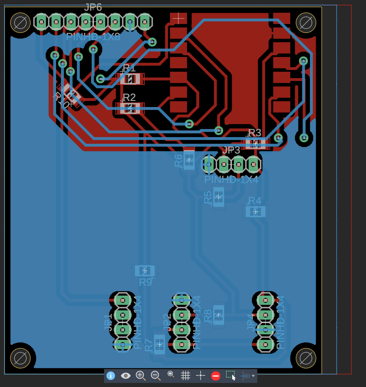
The base MirrorAge amplifier board milling initially failed due to polygon pour isolation settings. The default isolation distance was set to 0 mil, which caused routing issues. After changing the back-side polygon pour isolation to 32 mil, the milling operation succeeded. When the shop closed, the design was upgraded to include a TFT screen. Both the base design and TFT-integrated versions will be milled together and tested.
2.4 Integrating Fabrication
Physical integration of fabricated components demonstrates successful coordination between mechanical and electrical subsystems. The watch board fits within the watch case, and the acrylic display integrates properly. Additional work remains for drilling mounting holes for electronics and routing power connections.
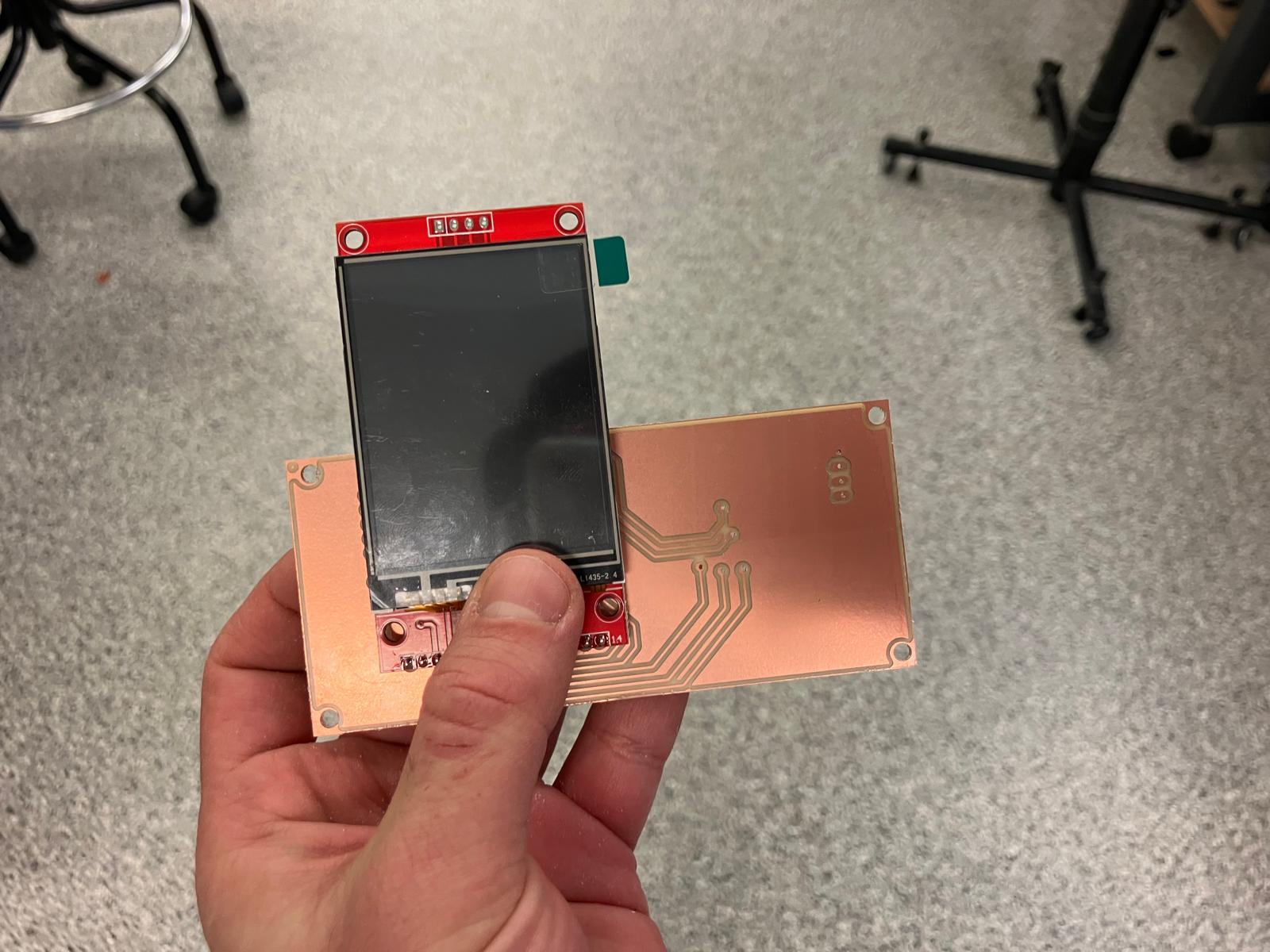
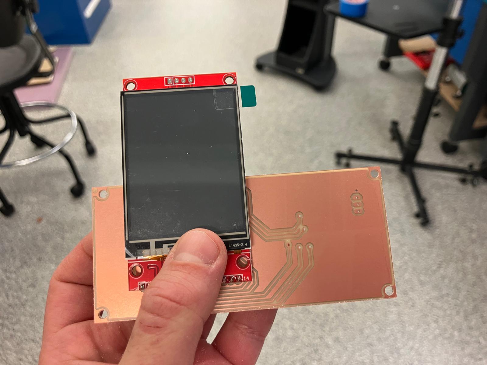
TFT Display Upgrades
Both board designs have been upgraded to include TFT displays, and integration testing confirms proper fit. The TFT watch board fits correctly with the TFT display, and both the base and TFT-integrated MirrorAge load cell-speaker boards fit within the gripper enclosure. Additional work is needed for drilling mounting holes and adding hooks for load cell wire routing to the HX711 mounted on the board, as well as routing power connections.
Day 4: Subsystem Integration
Comprehensive subsystem integration work combining 2D fabrication, 3D printing, PCB milling, and molding/casting to complete all physical components for final assembly and testing.
2.0 Final Electrical Design Upgrades
With the milling machine unavailable, the time was used to upgrade board designs, requiring component rotations and layout optimizations to ensure all components fit properly. As Quentin noted, "you have to get used to rotating it in your head"—a valuable skill for PCB design where spatial reasoning is essential for component placement and routing.
"you have to get used to rotating it in your head" — Quentin
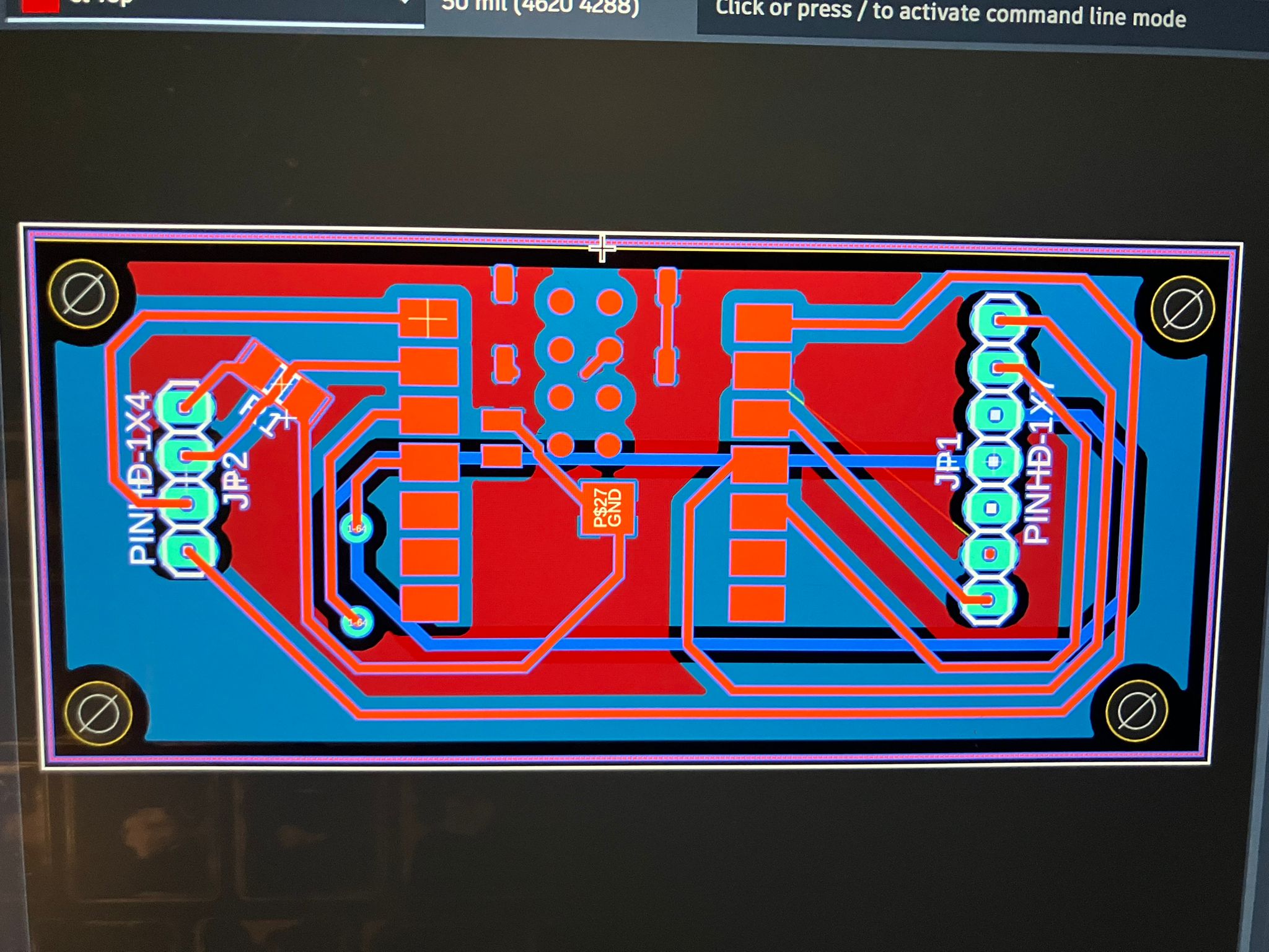
MirrorAge TFT Board Upgrades (v13)
The MirrorAge TFT board design was upgraded to version 13, with component rotations and layout optimizations to improve fit and routing efficiency.
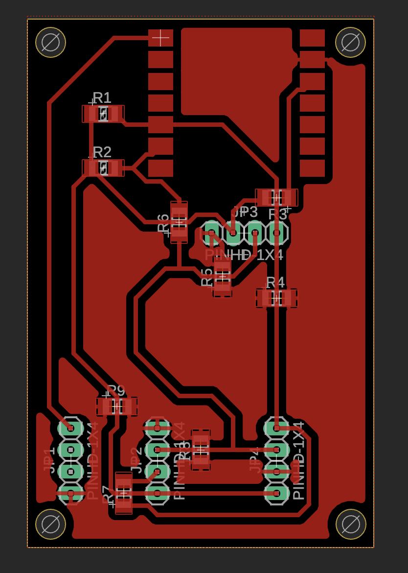
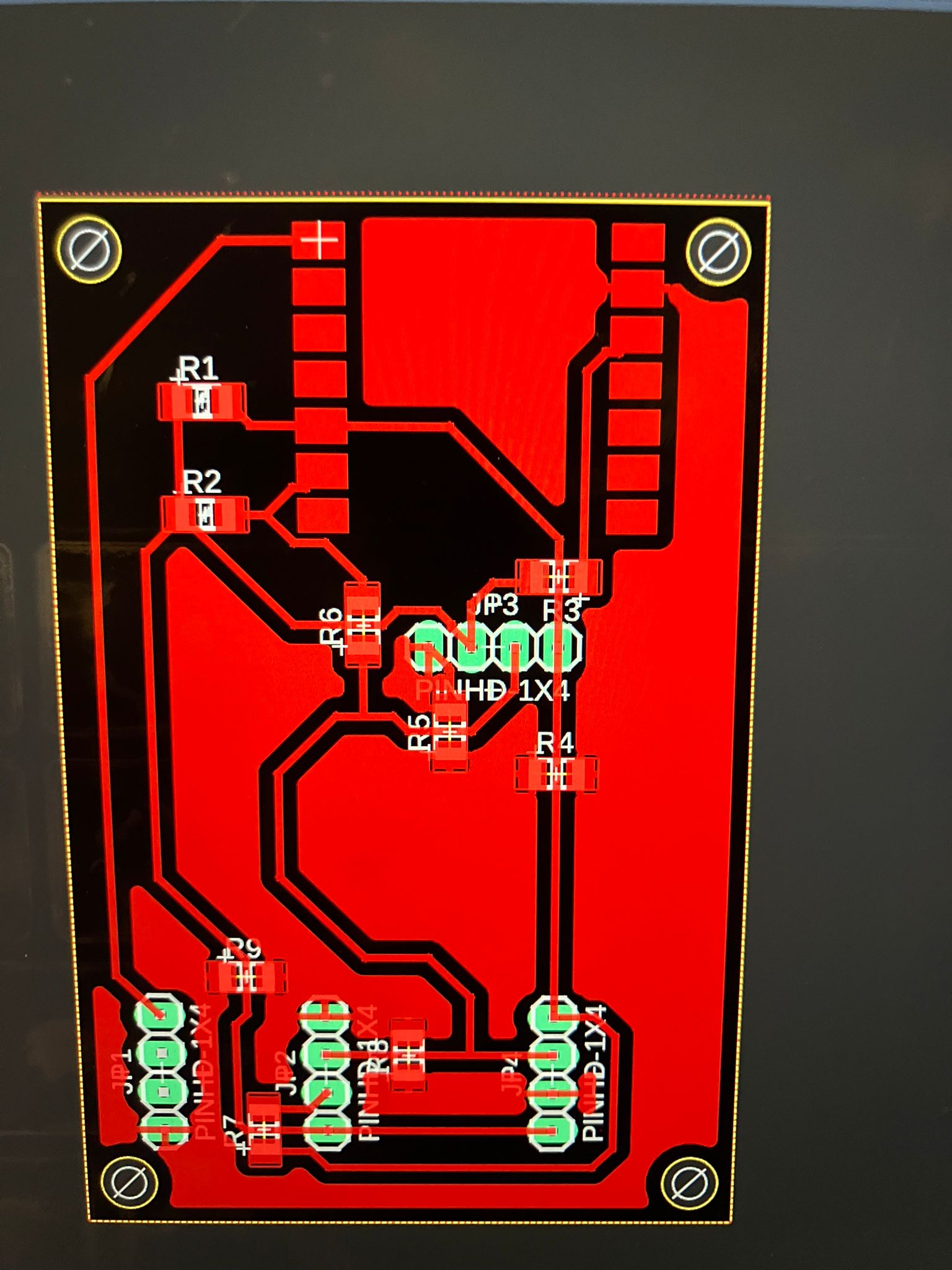
Aging Clock TFT Board Upgrades (v16)
The aging clock TFT board design was upgraded to version 16, incorporating component rotations and layout refinements to ensure proper fit within the watch casing constraints.
As part of this upgrade, the board was rotated 90° so that the USB power and programming cable can be routed cleanly through the side button openings of the watch enclosure, avoiding strain on the connector and preserving clearance for the bands.
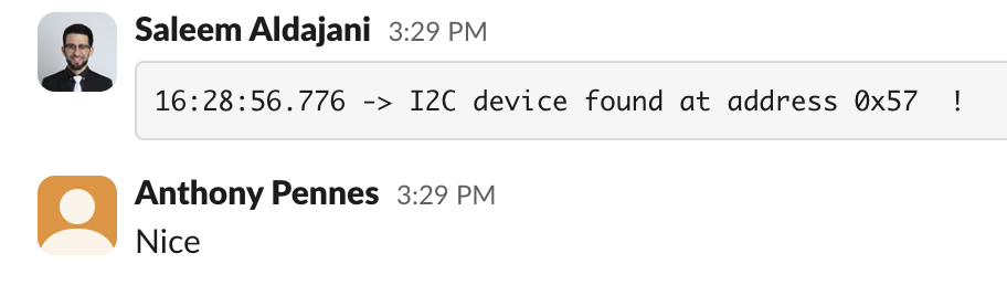
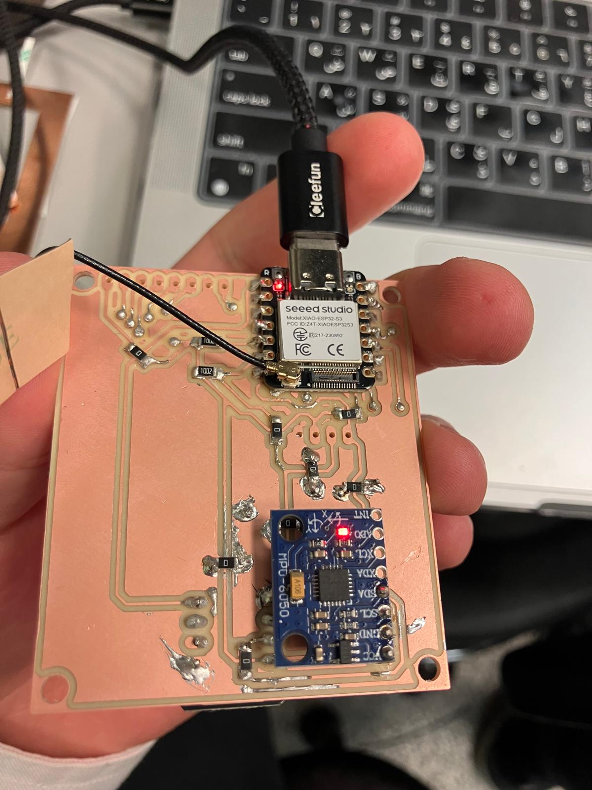
2.6 I²C Bring-Up and Future Electrical Robustness
Subsystem integration also focused on making the shared I²C bus predictable and debuggable. During flashing, an intermittent serial exception from esptool indicated that the USB device was reporting readiness but returning no data—a classic symptom of a loose cable, port contention, or transient power issue rather than a firmware bug. After power-cycling the board, checking that only one serial monitor was attached, and reseating the USB cable, flashing succeeded reliably.
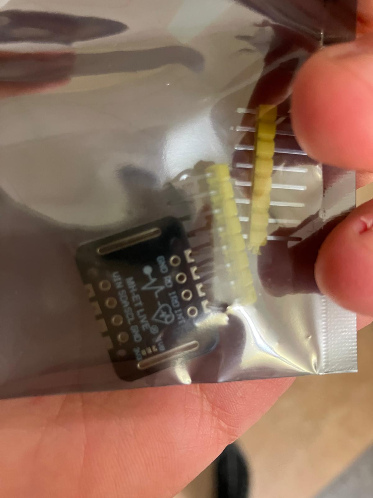
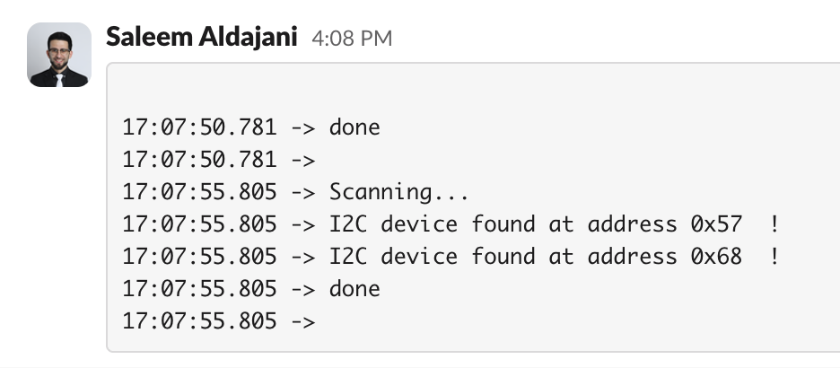
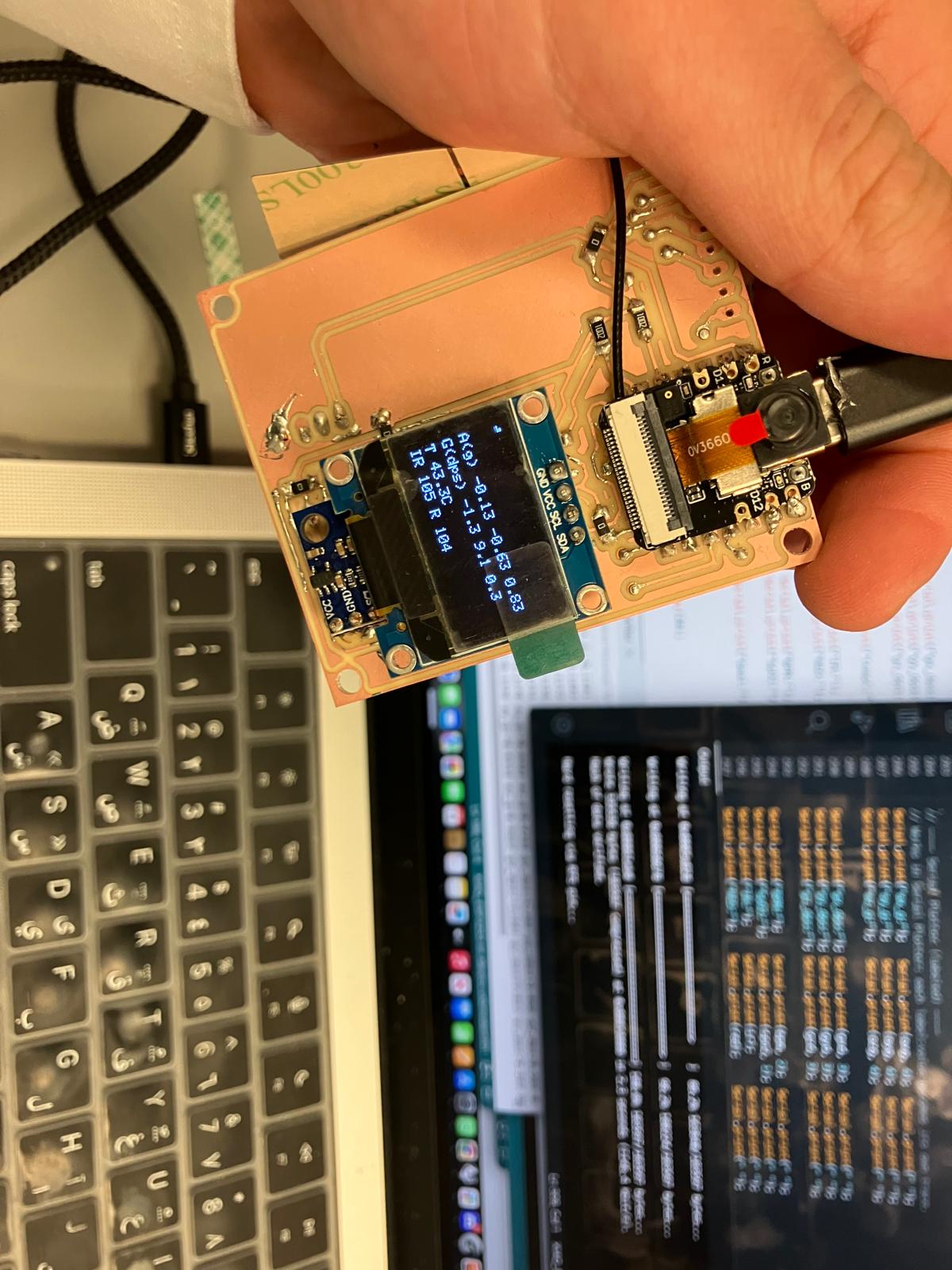
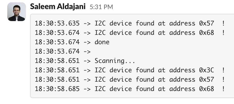
With stable flashing restored, an I²C scanner sketch confirmed that all devices were present on the bus: the MAX30102 pulse oximeter at address 0x57, the MPU6050 accelerometer at 0x68, and the OLED display at 0x3C once it was wired in. Multiple scans over time reproduced the same addresses, validating bus integrity and confirming that the SDA/SCL routing and pull-up strategy were correct after earlier trace and enclosure fit issues.
- Keep I²C traces short, avoid sharp mechanical pinch points near the enclosure, and leave clearance for solder thickness to prevent pads from lifting under pressure.
- Standardize on known-good I²C addresses (MAX30102
0x57, MPU60500x68, SSD1306 OLED0x3C) and document them close to the schematic and firmware. - Use a simple I²C scanner and a dedicated flashing machine to separate bus-debug issues from USB driver or multi-process serial conflicts.
Reference: esptool Troubleshooting Guide for interpreting serial upload errors and recommended recovery steps.
2.1 2D Fabrication: Laser Cutting
Laser-cut thinner acrylic (1.35mm) was fabricated to improve the fit of the clear display cover for the aging clock subsystem. The thinner material provides better dimensional tolerance and improved integration with the watch casing.
2.2 3D Printing: Rigid and Flexible Components
Band clips were printed using TPU (Thermoplastic Polyurethane) material for improved fit and flexibility. The flexible material provides better mechanical compliance and secure attachment to the watch body.
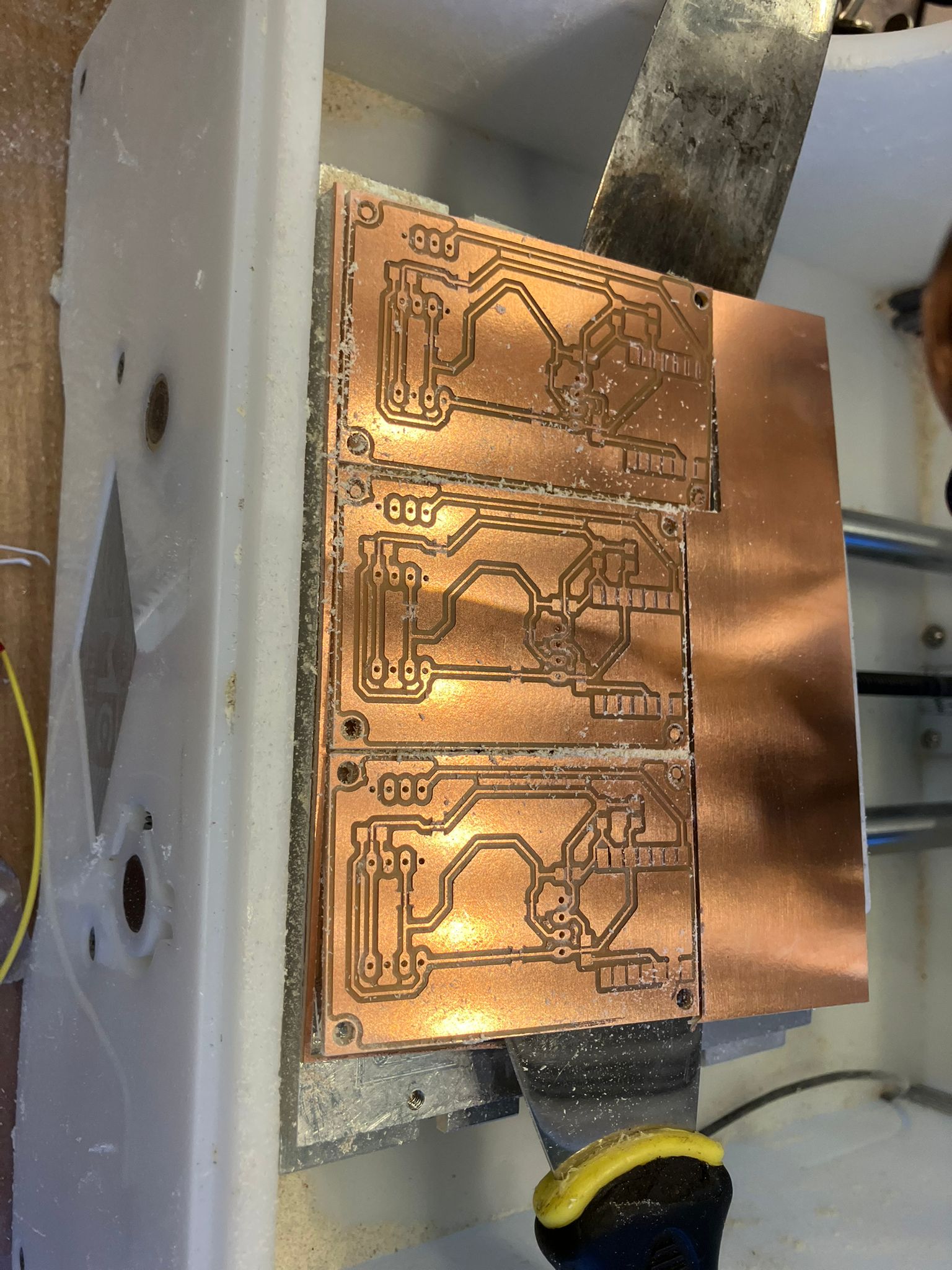
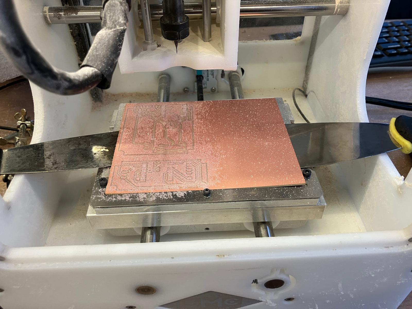
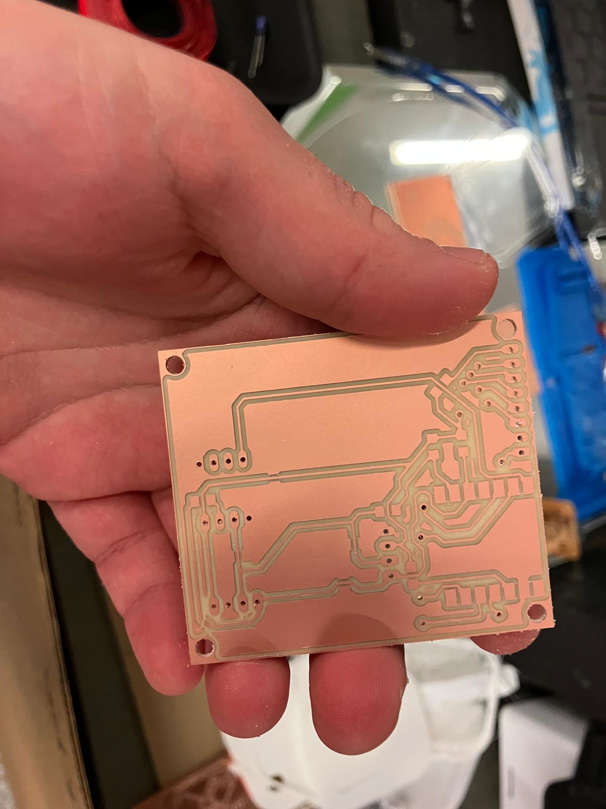
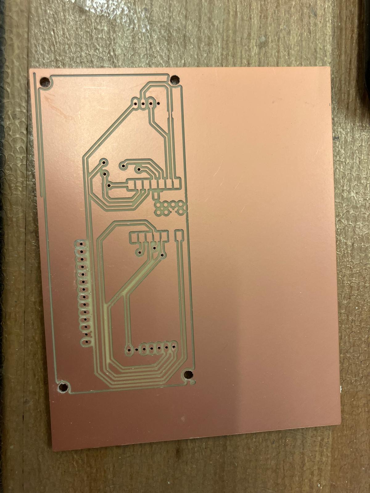
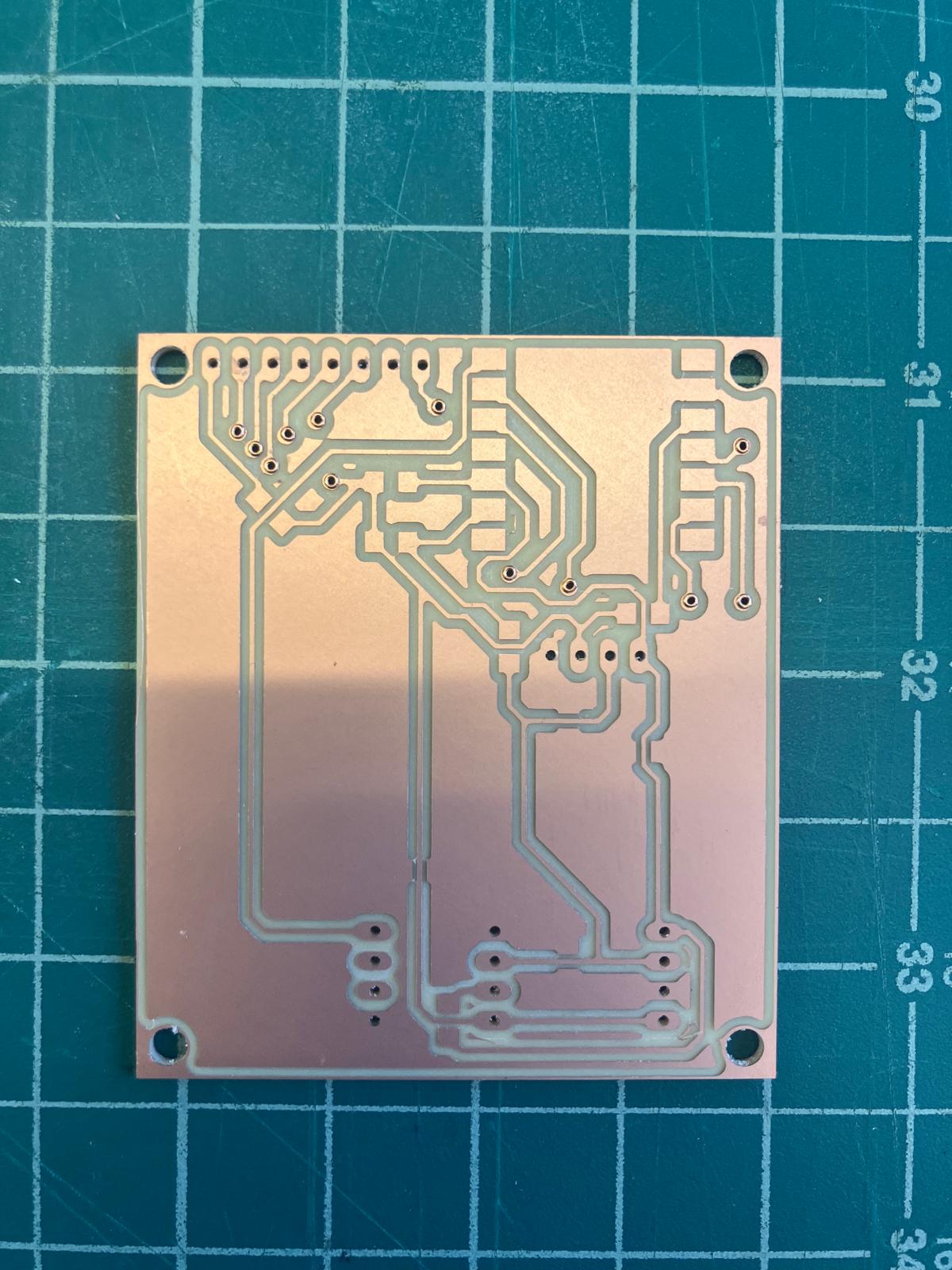
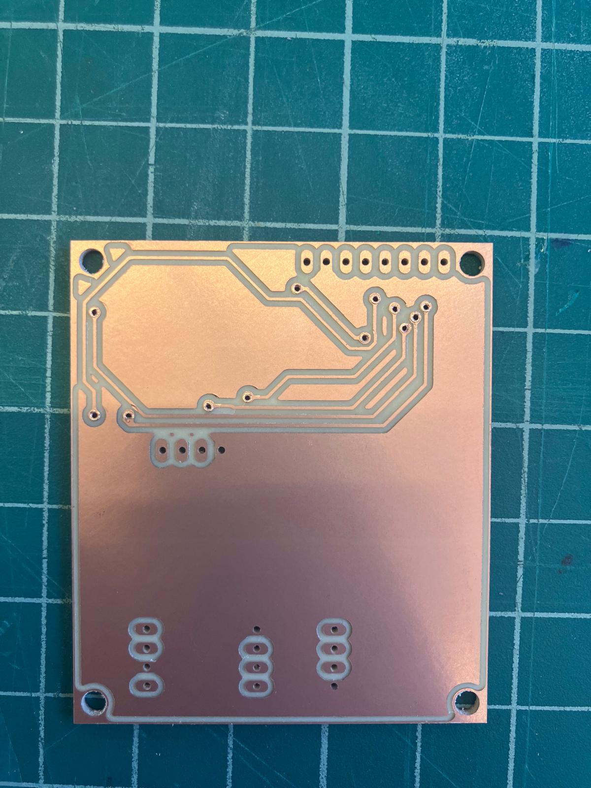
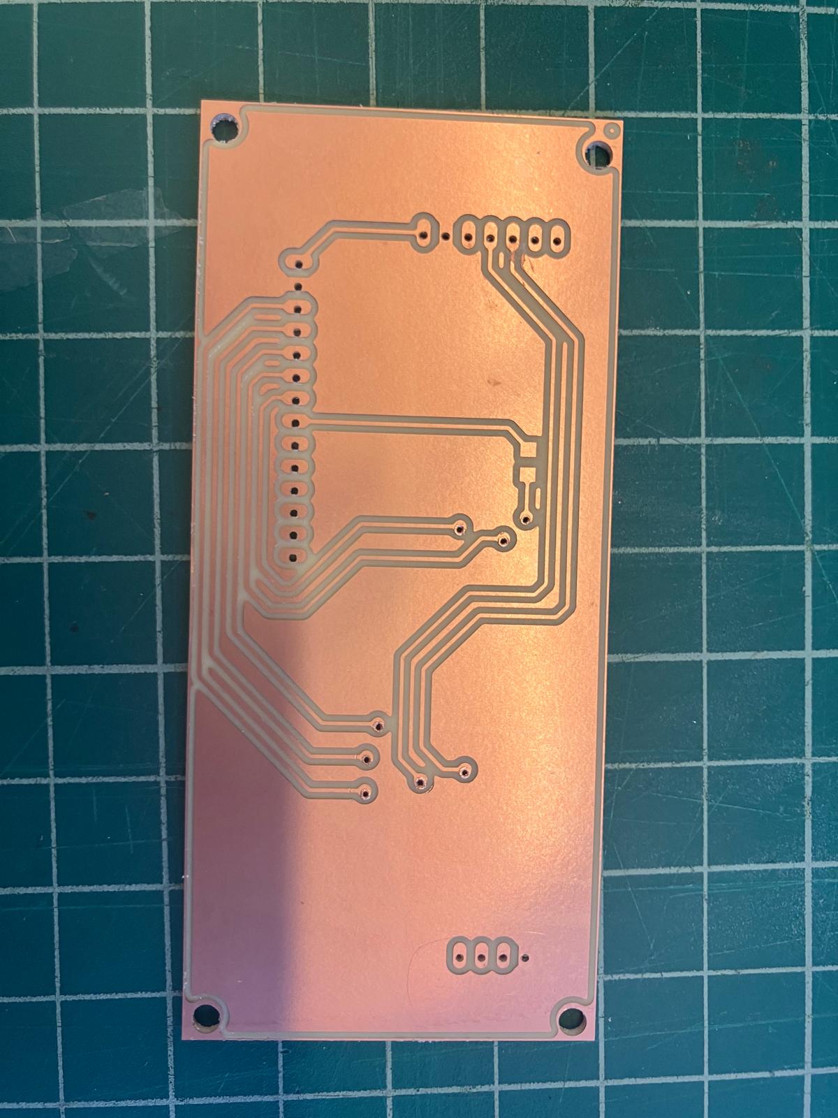
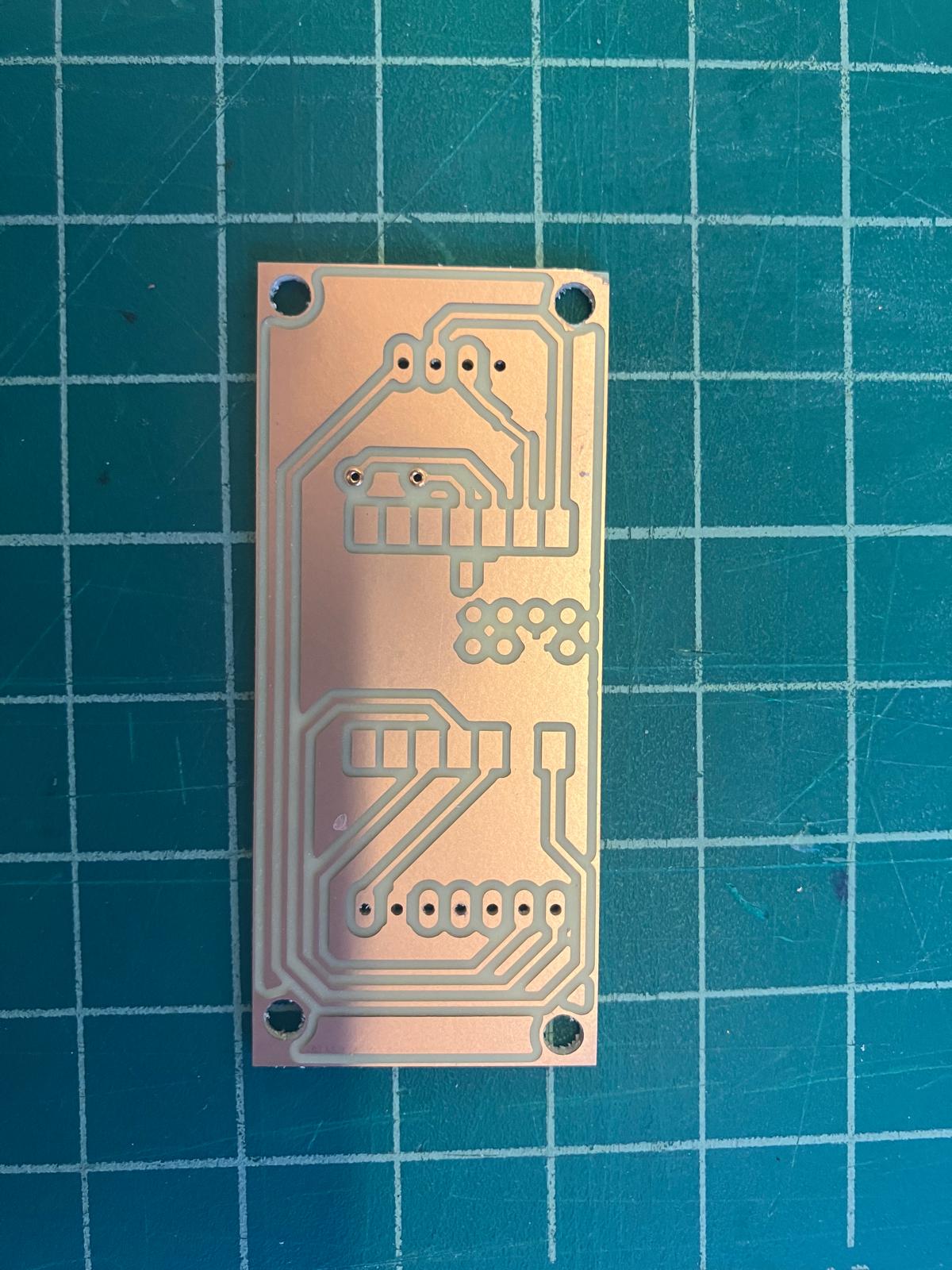
2.3 Milling: Single and Double-Sided Boards
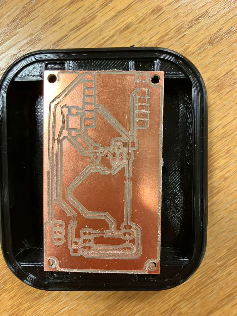
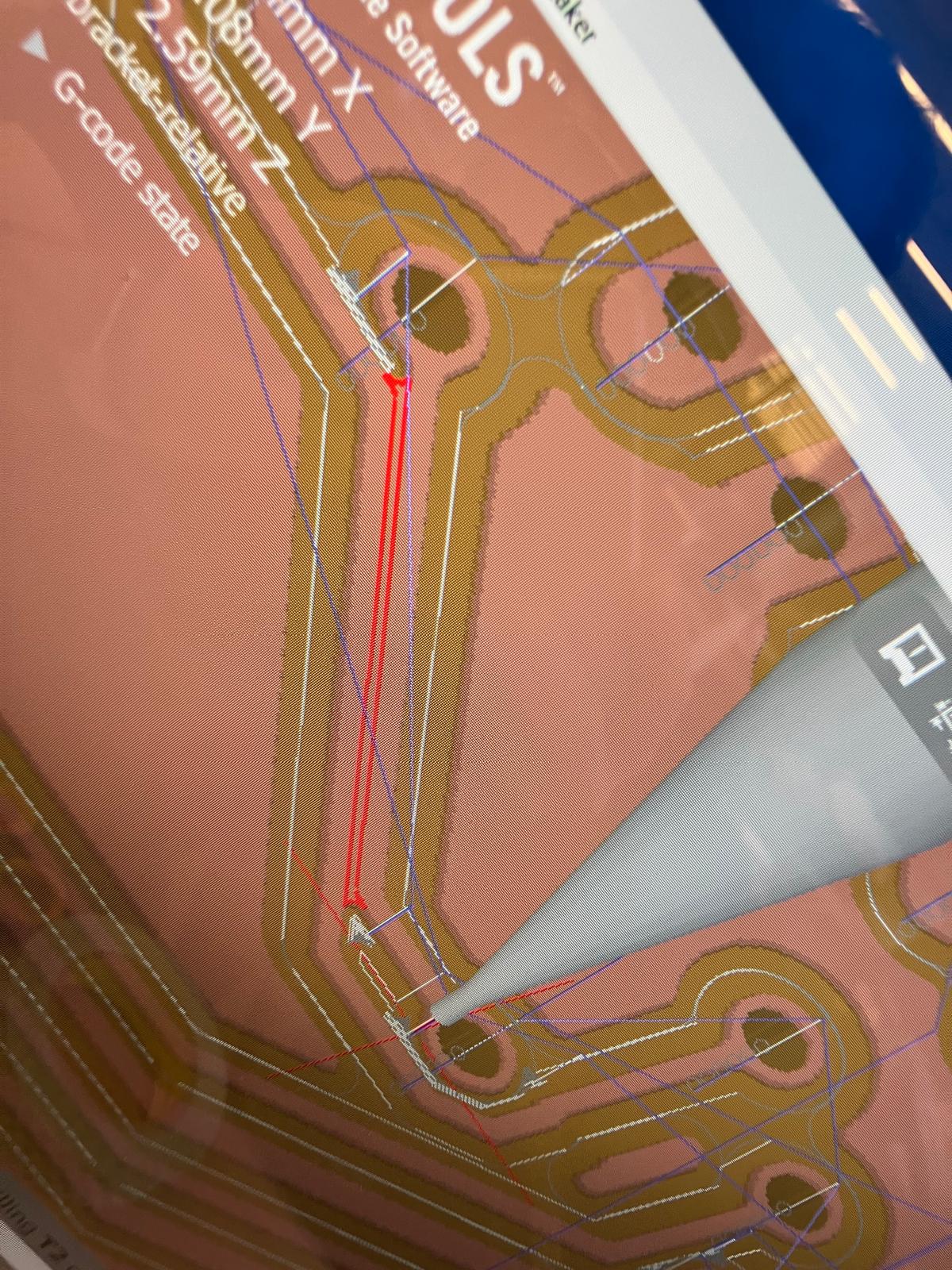
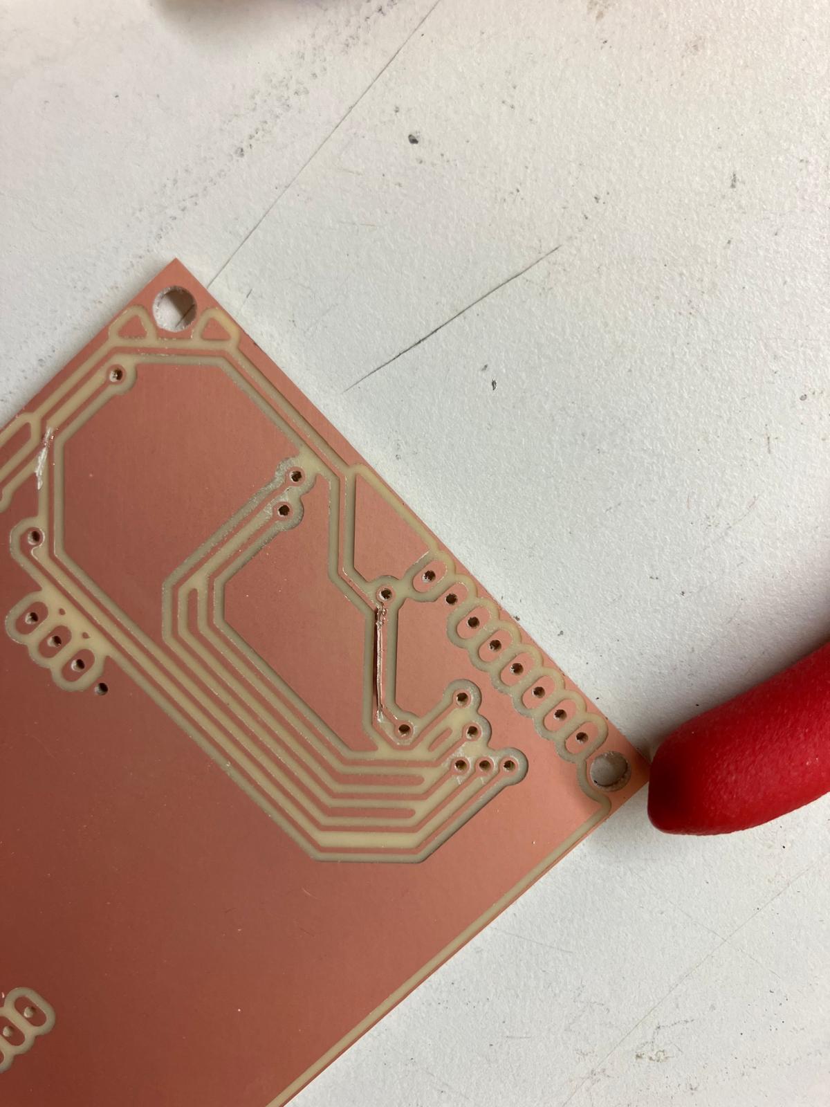
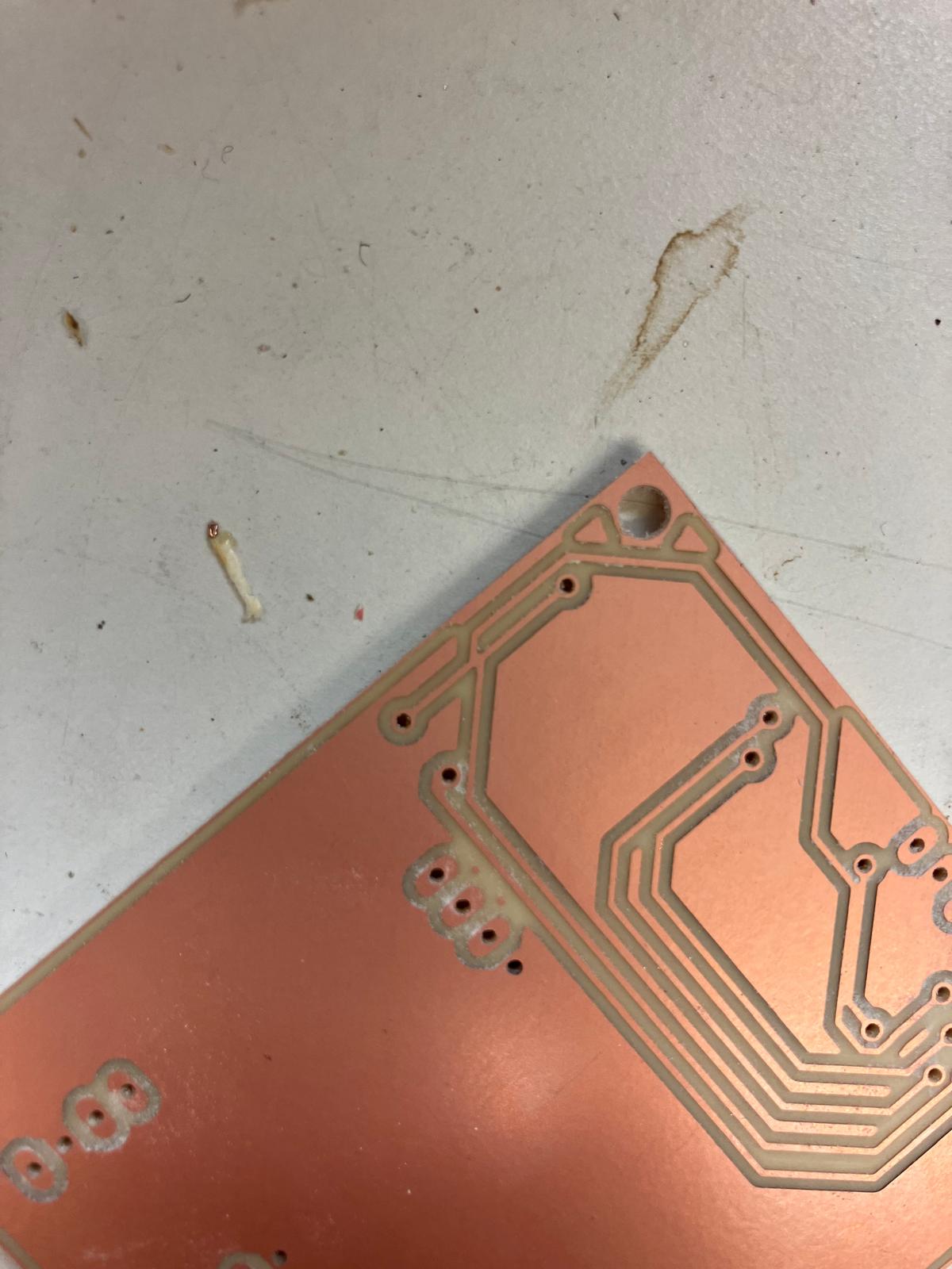
The TFT aging clock board design was milled, requiring iterative refinement due to initial design issues. The first mill had traces that were too close together, and the rivets were positioned under the microcontroller, requiring manual fixes with an ultrasonic knife before remilling the corrected board.
First Milling Attempt
The initial milling process revealed design issues that required correction. The board was milled on both front and back sides, with careful tool location and fixturing procedures.
Design Issues and Manual Fixes
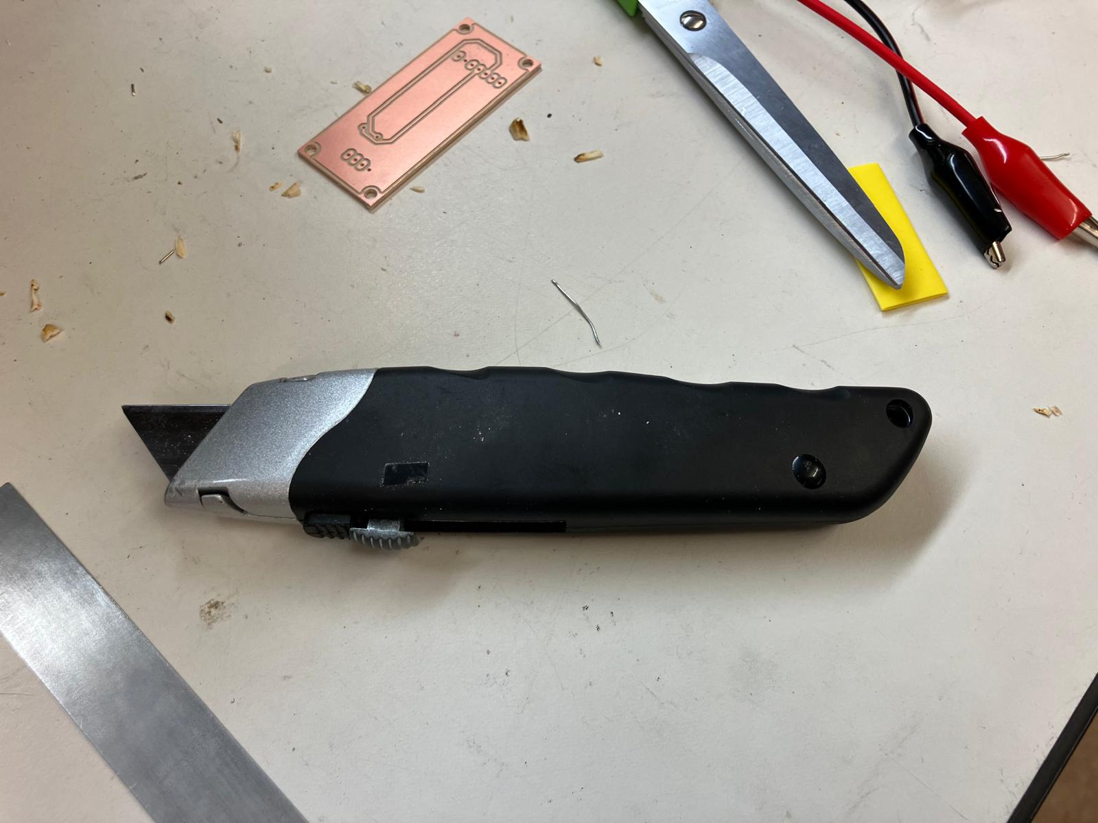
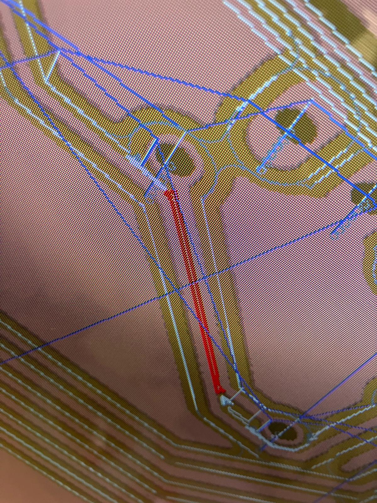
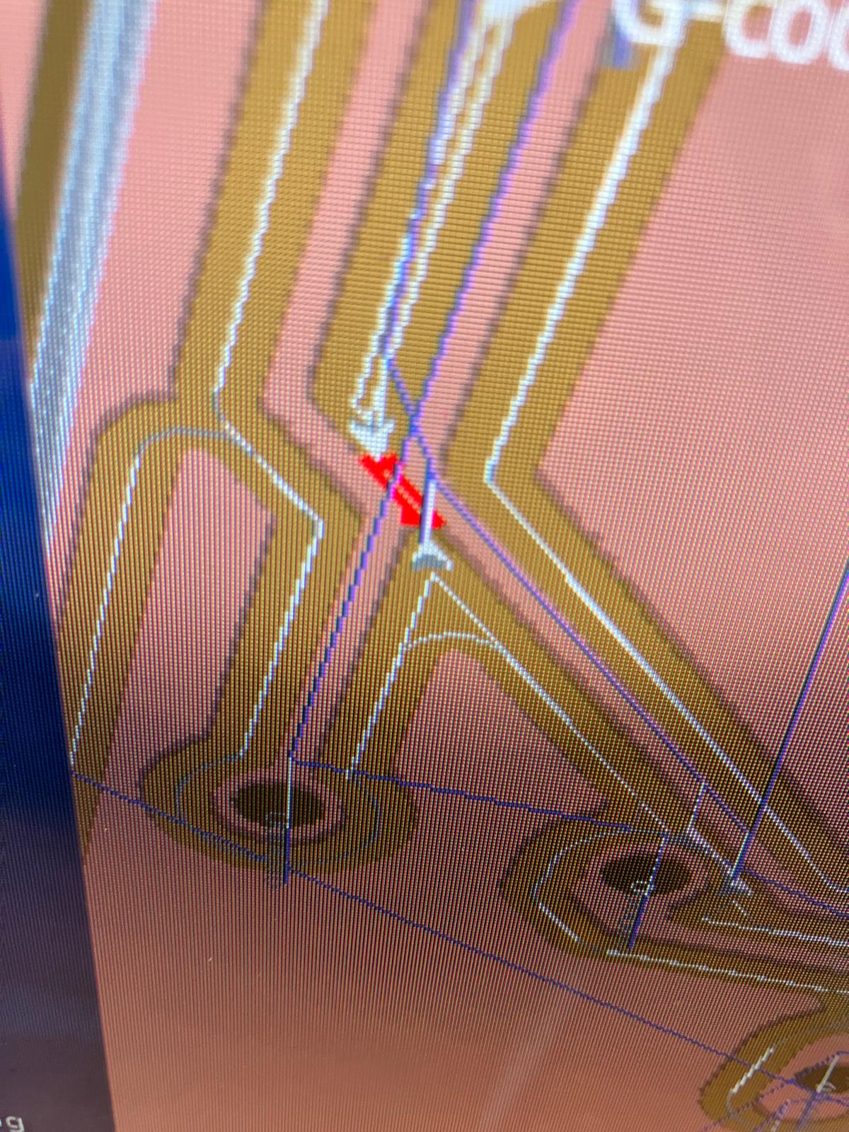
After milling, inspection revealed traces that were too close together and rivets positioned under the microcontroller. These issues were corrected manually using a two-step cutting process: the ultrasonic knife was used to initiate precise cuts on both ends of each problematic trace, establishing the correct penetration direction. A utility knife was then used to cut a straight line between these initiation points, isolating the upper and lower wiring. The challenge with manual trace cutting lies in controlling the initial penetration with the utility knife—the ultrasonic knife's precision in establishing the cut direction made the subsequent utility knife cut smoother and easier to complete from end to end. After these manual corrections, the board design was updated and remilled with the fixed layout.
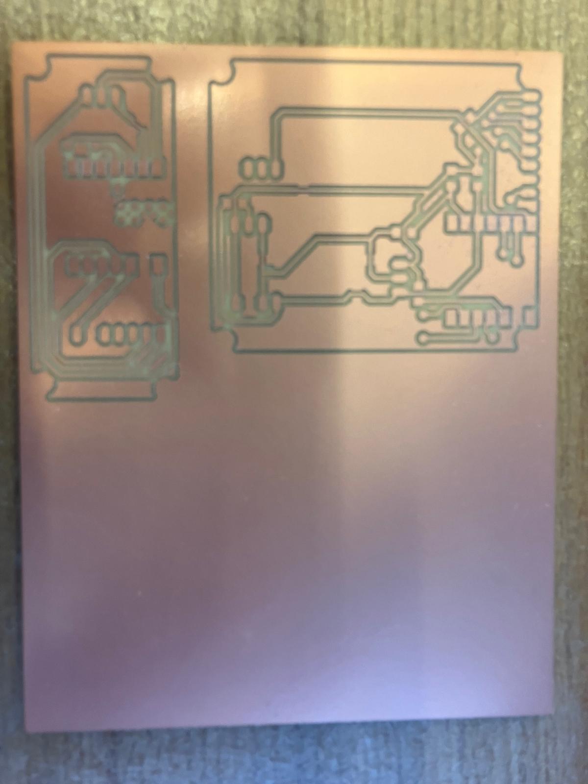
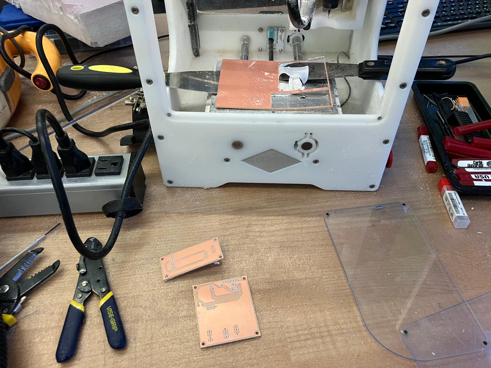
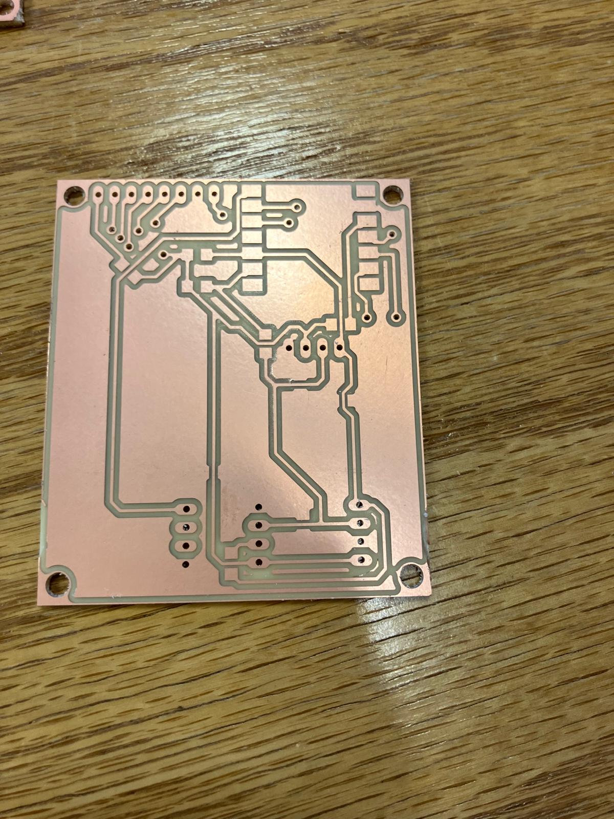
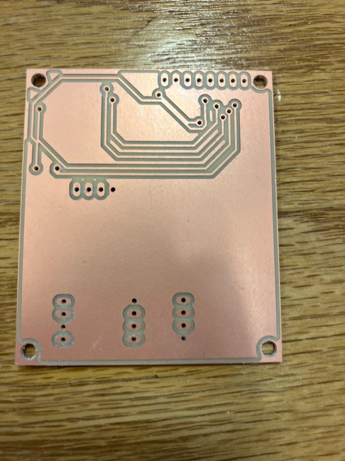
Corrected Board Design and Remilling
After manual corrections, the board design was updated to move rivets away from the microcontroller and improve trace spacing. The corrected board was successfully milled with proper trace clearances and component placement.
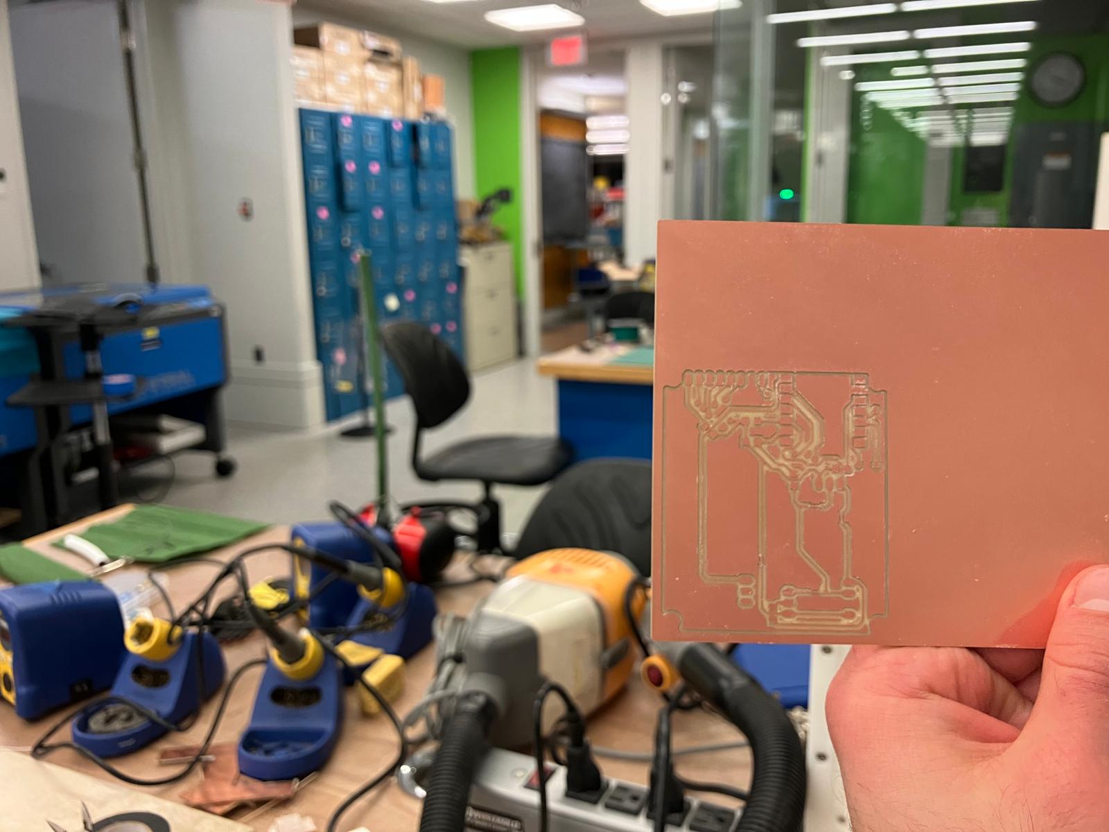

MirrorAge TFT Board Milling
The base amplifier board was remilled after fixing polygon pour isolation settings (changed from 0 to 32 mil). The upgraded MirrorAge board with TFT display was also successfully milled, ready for soldering and testing.
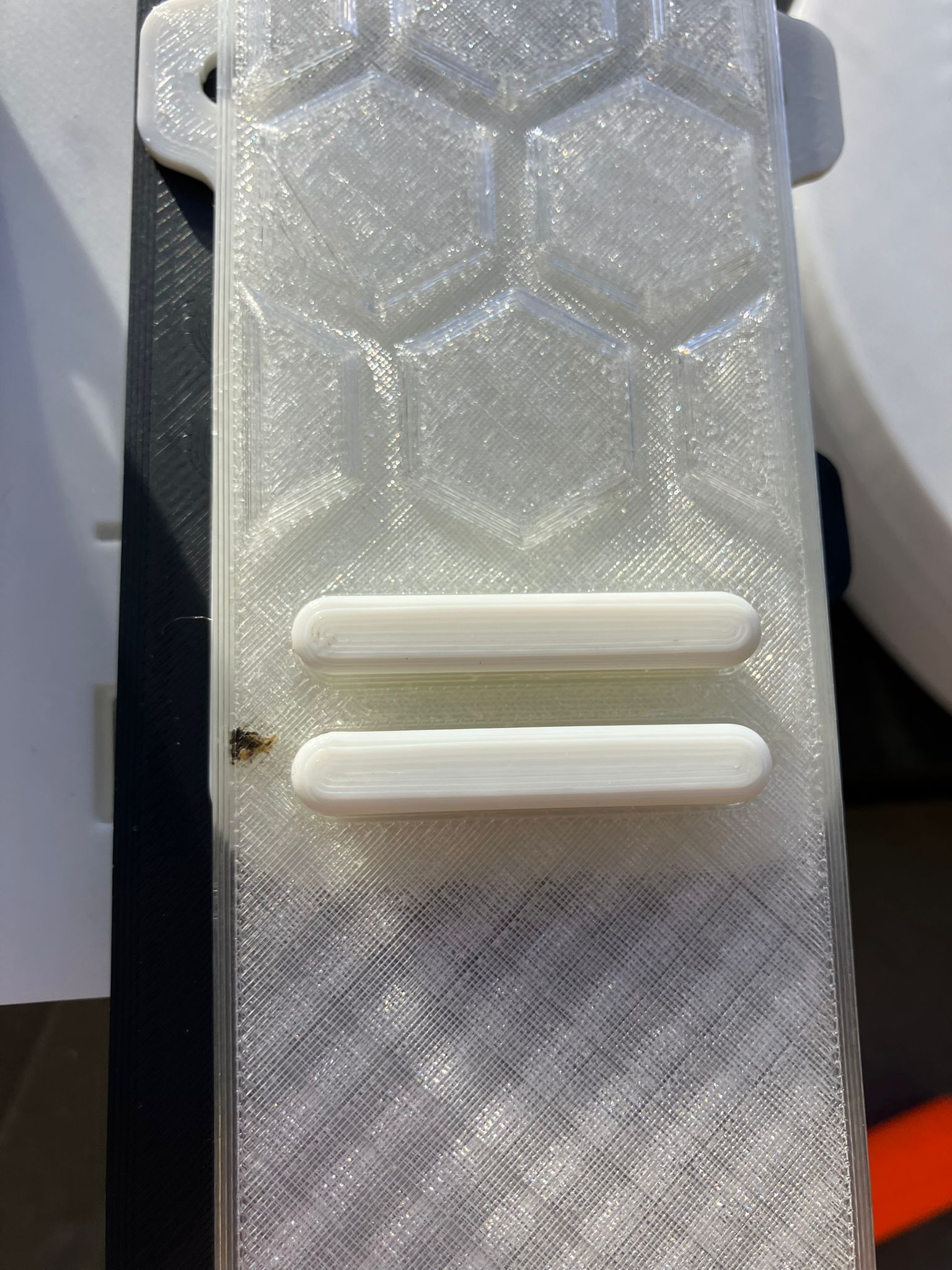
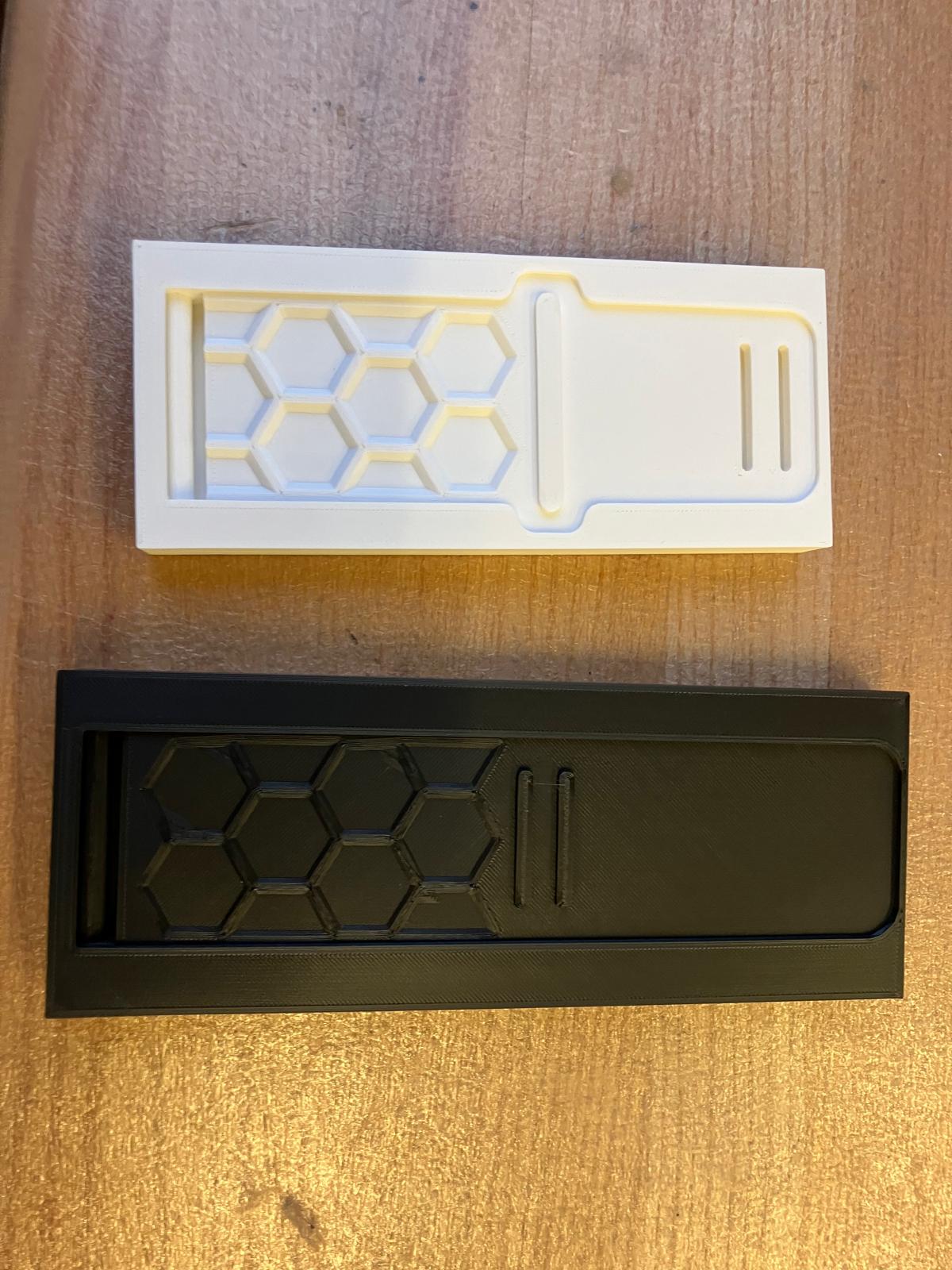
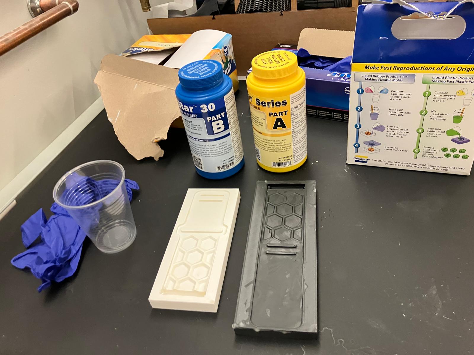
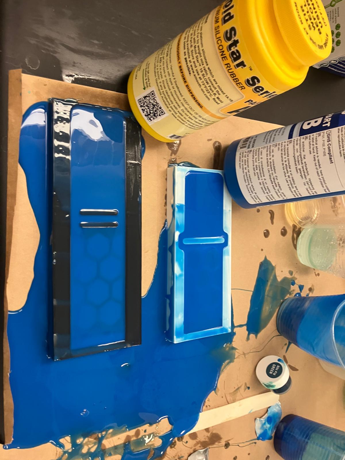
2.4 Molding and Casting
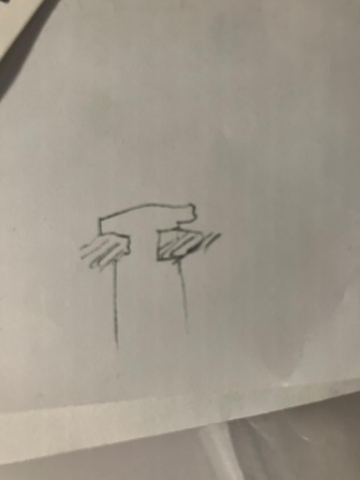
Starting from Anthony's sketch in the midterm review, 3D-printable open molds were designed to cast watch bands out of MoldStar 30. The process involved printing PLA molds, waxing for release, mixing and pouring the mold material, leveling, curing under a heat lamp, and demolding. The center section of the printed molds required cutting with an ultrasonic knife before pouring to ensure part removability. A backup TPU band was also printed in case of casting failure.

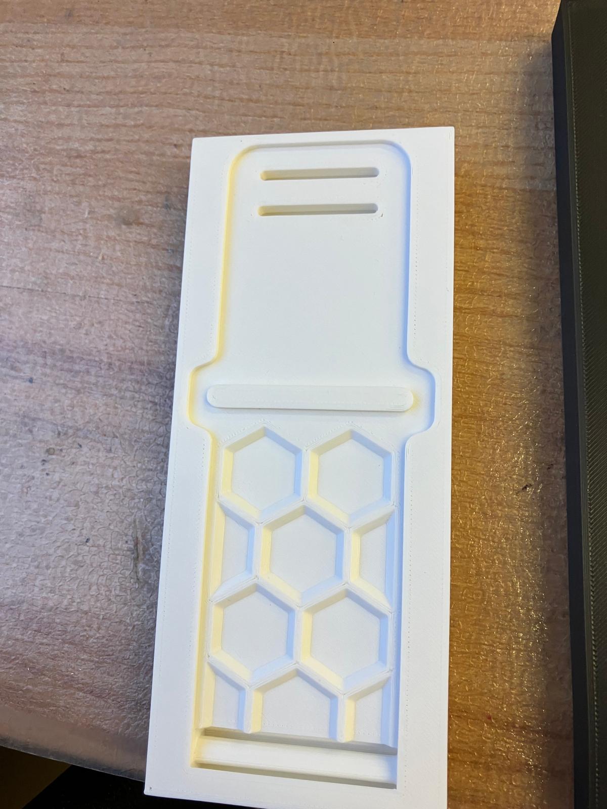
Mold Preparation
The molds required cutting out the center section with an ultrasonic knife before waxing and casting. Wax was melted, painted onto the mold surfaces for release, and thinned as needed for proper coverage.
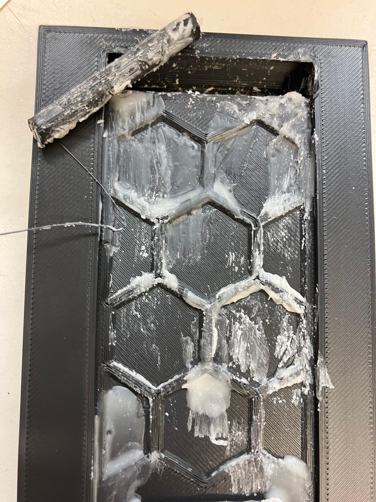
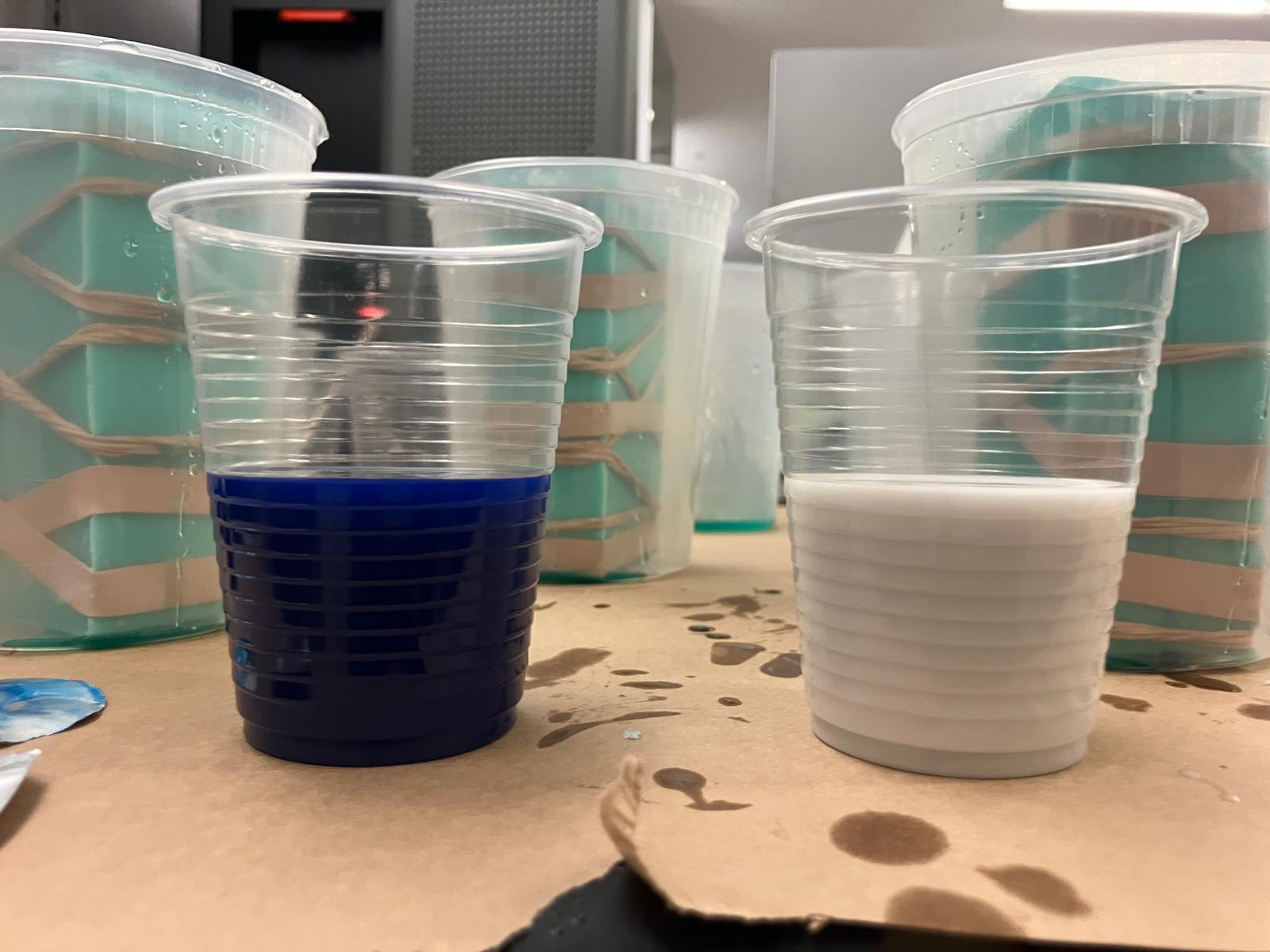
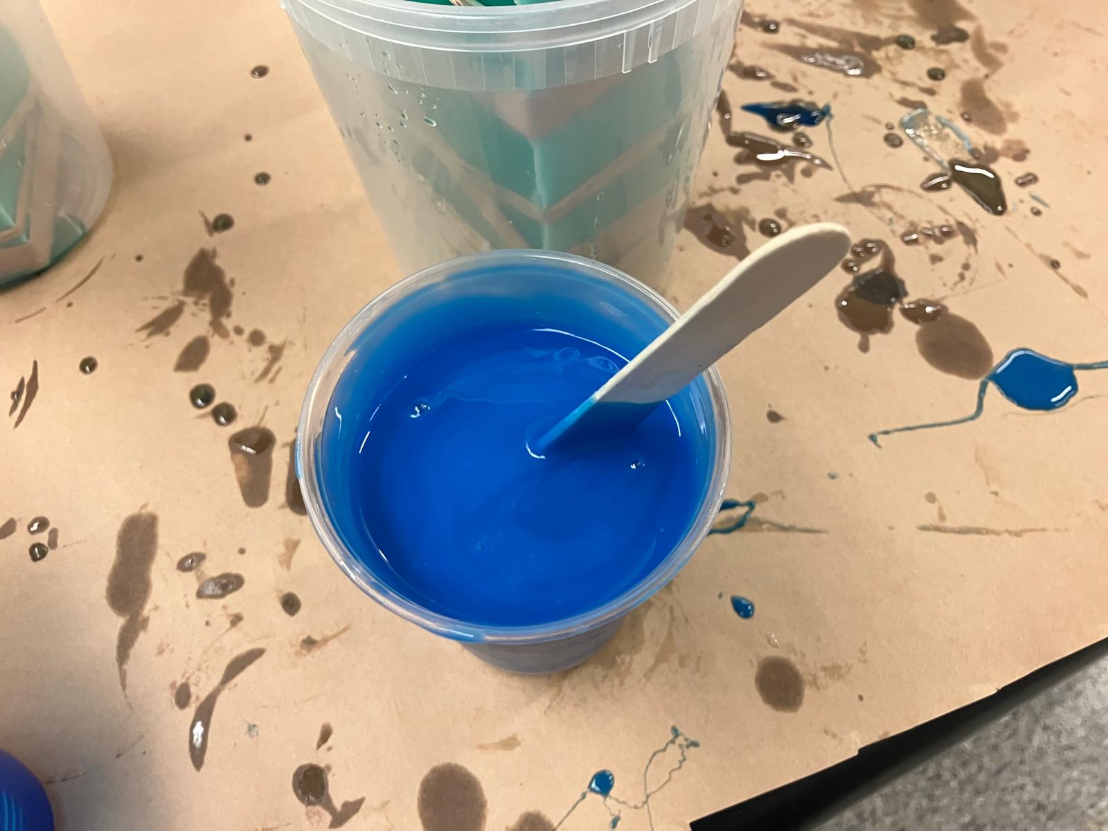
Mold Mixing and Pouring
MoldStar 30 was mixed according to specifications, poured into the prepared molds, and leveled to ensure proper distribution and surface quality.
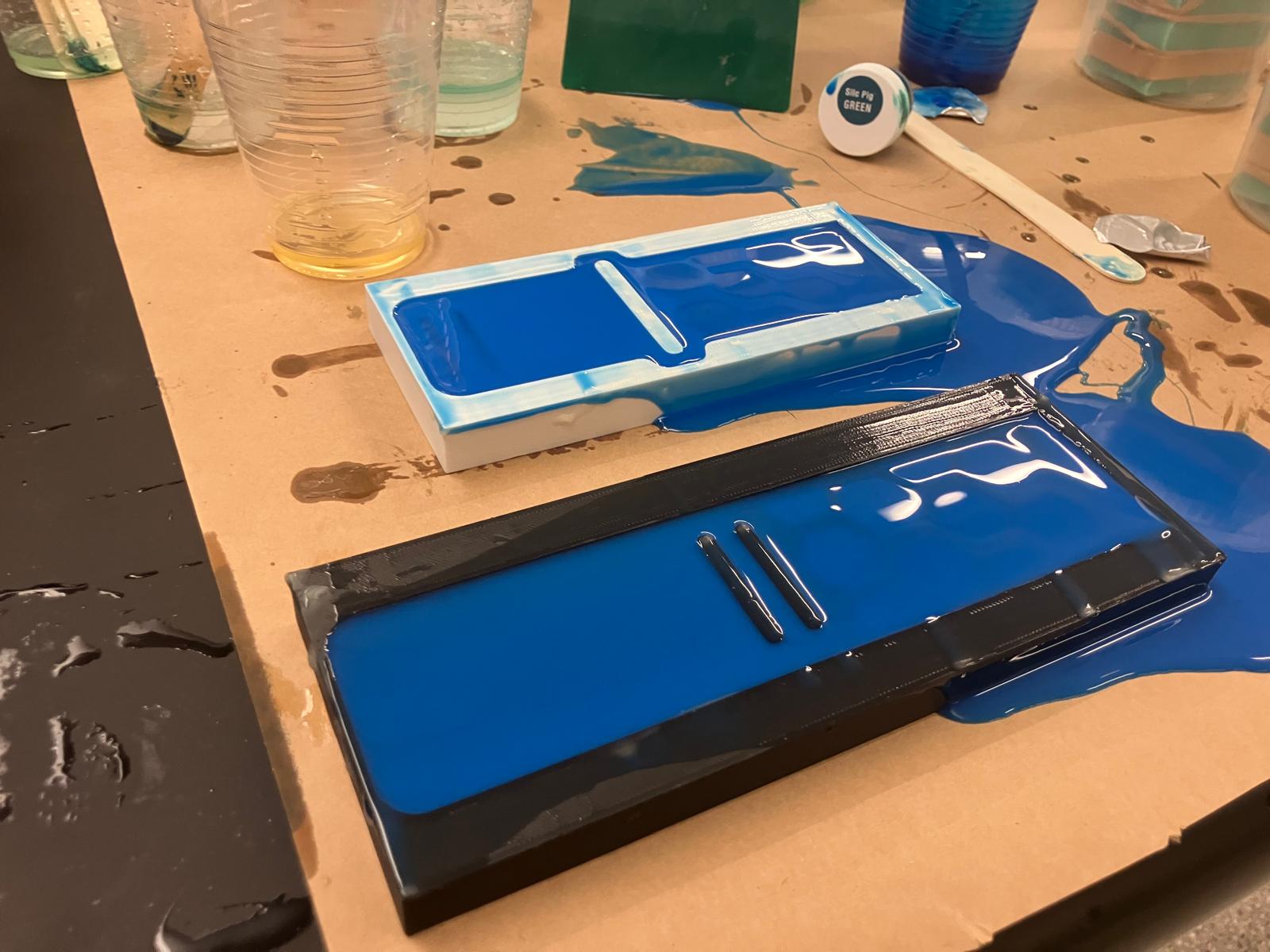
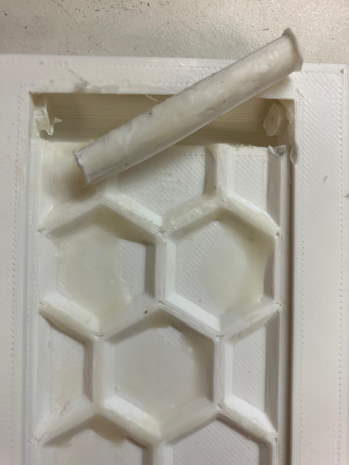
Curing and Demolding
The filled molds were moved under a heat lamp for curing, then demolded and tested to ensure proper fit between the two band halves.


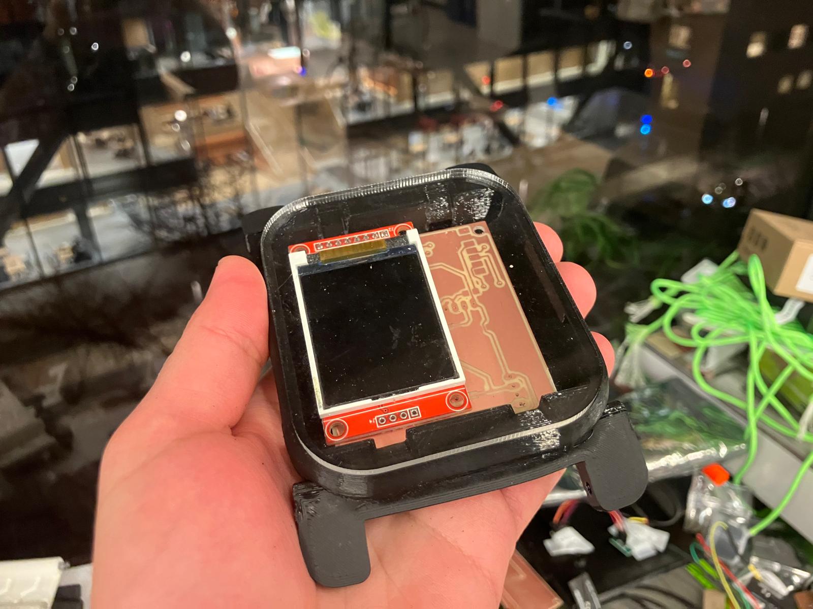
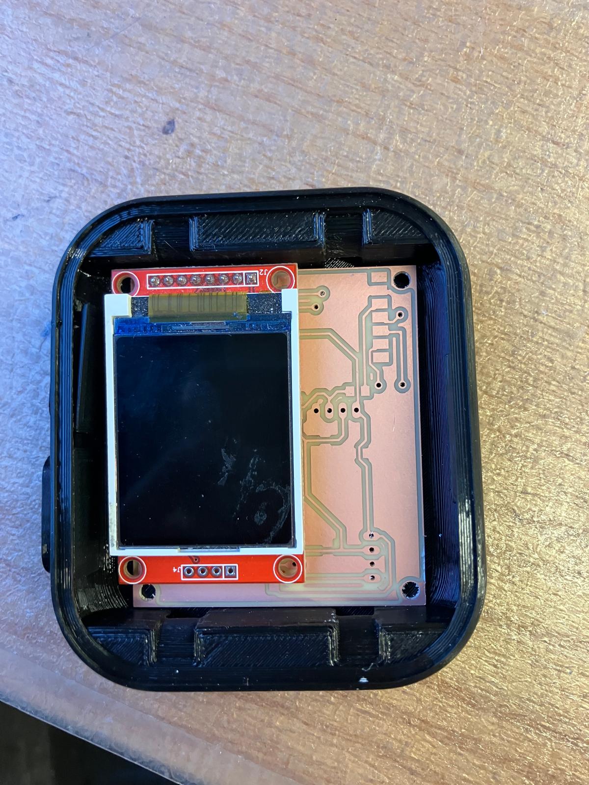
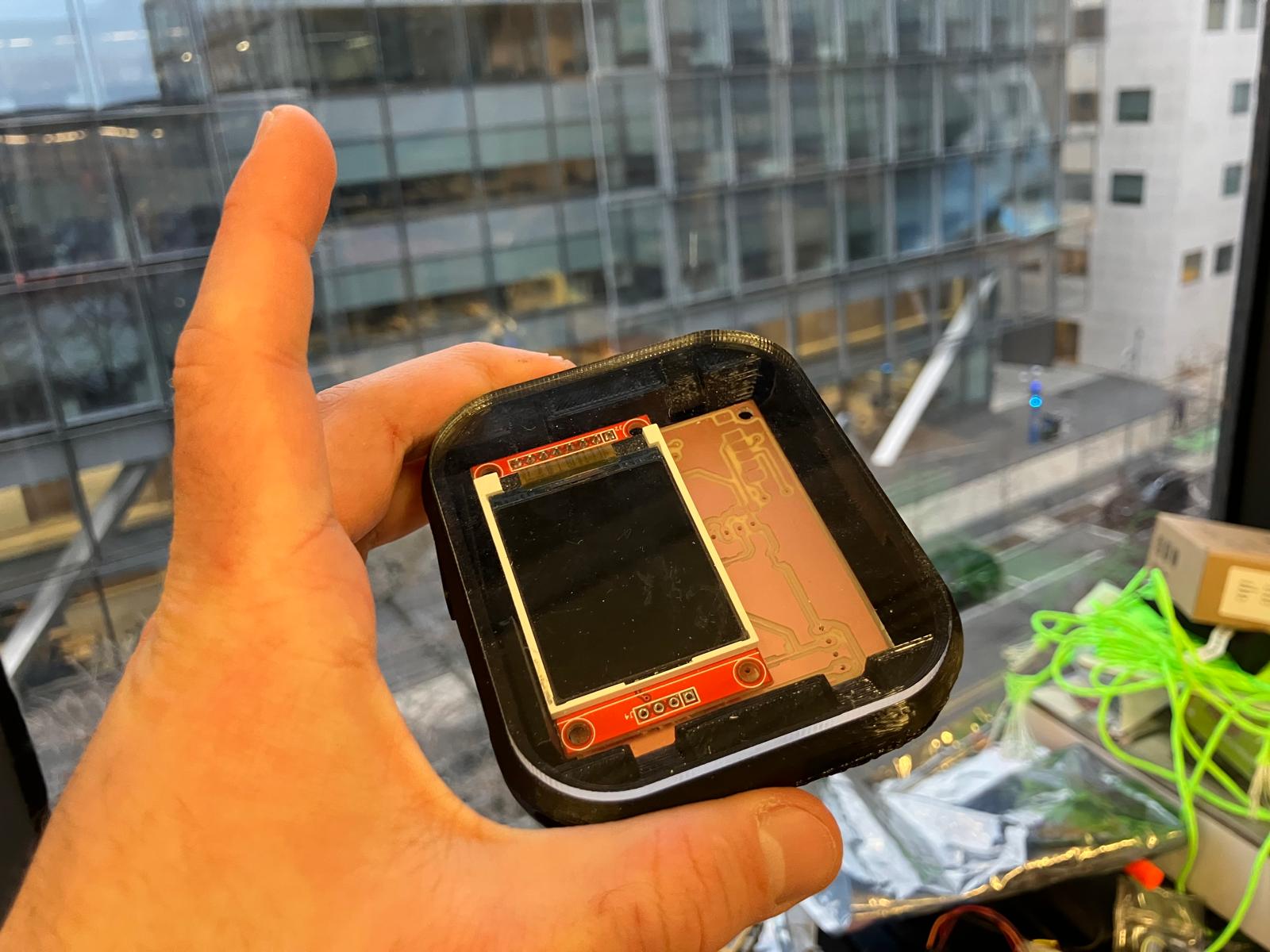
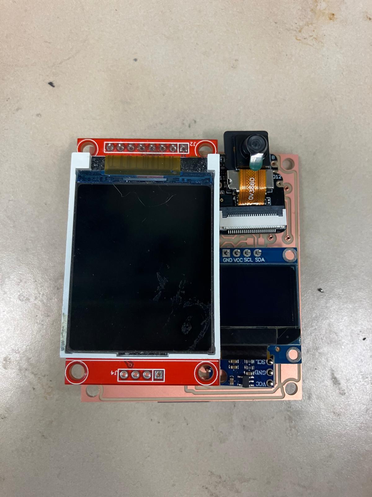
2.5 Aging Clock Subsystem Fabrication
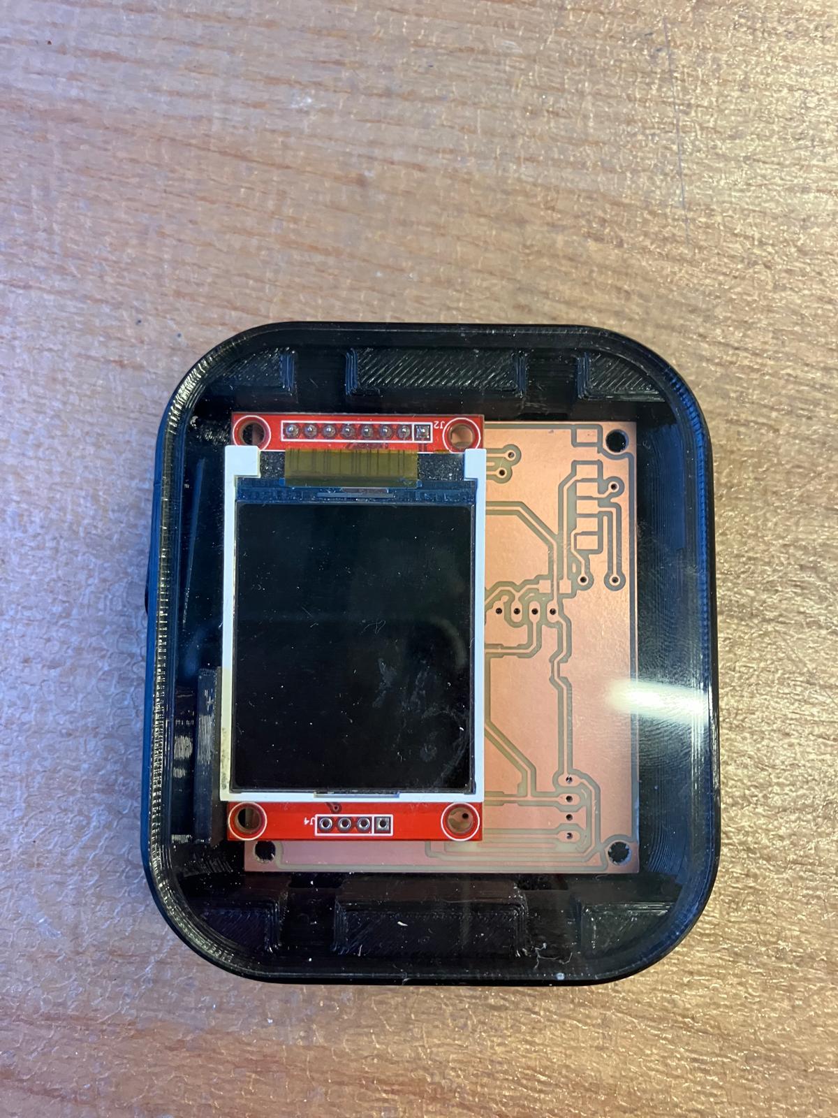
The TFT aging clock board was successfully assembled into the watch enclosure, demonstrating successful integration of all fabricated components including the milled PCB, TFT display, and watch casing.
Day 5: Full System Integration
Final integration day focused on closing the watch subsystem as far as mechanically feasible, soldering and verifying all double-sided boards, refining molded bands, and assembling the complete MirrorAge demo with both the aging clock and grip-strength subsystems fully wired and tested.
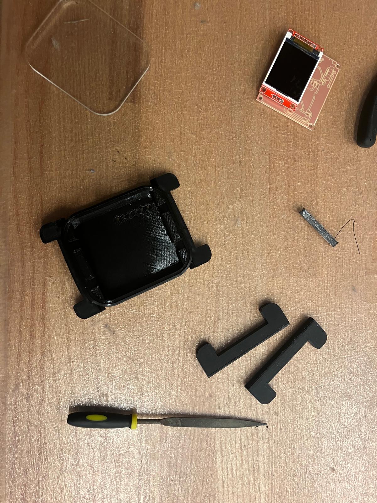
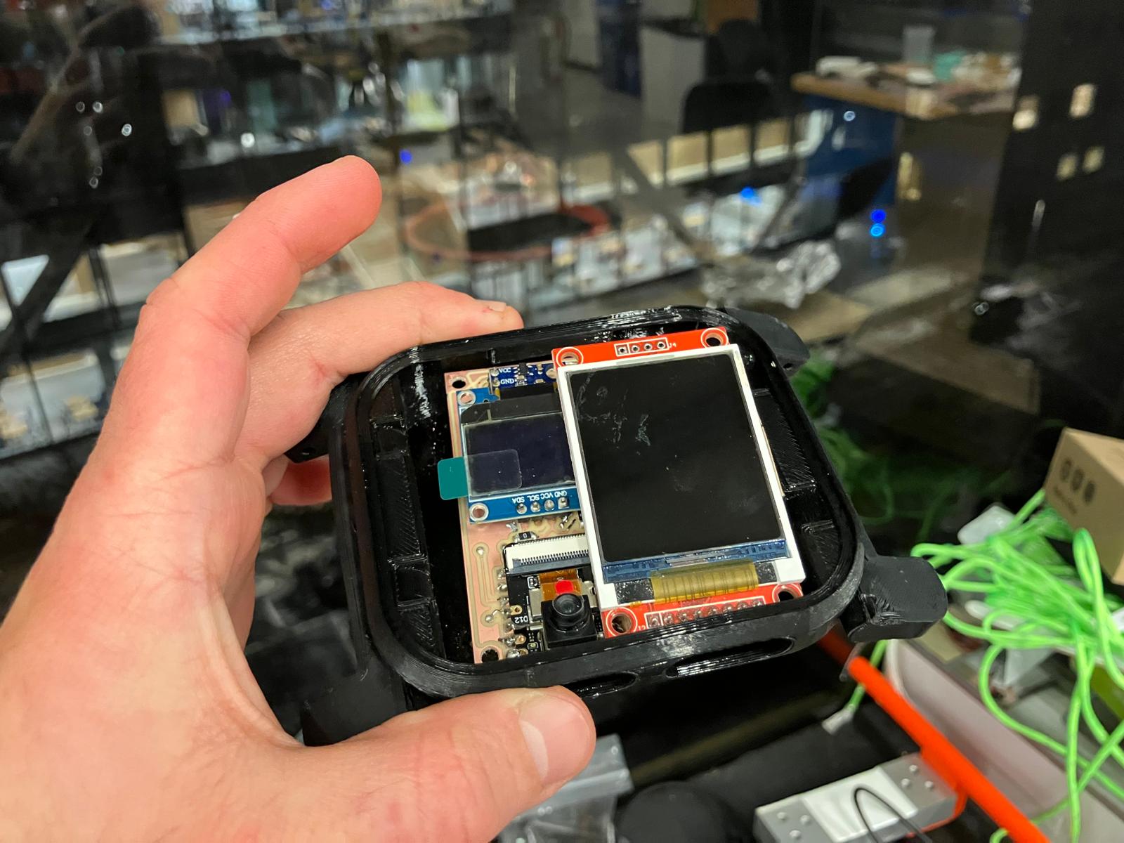
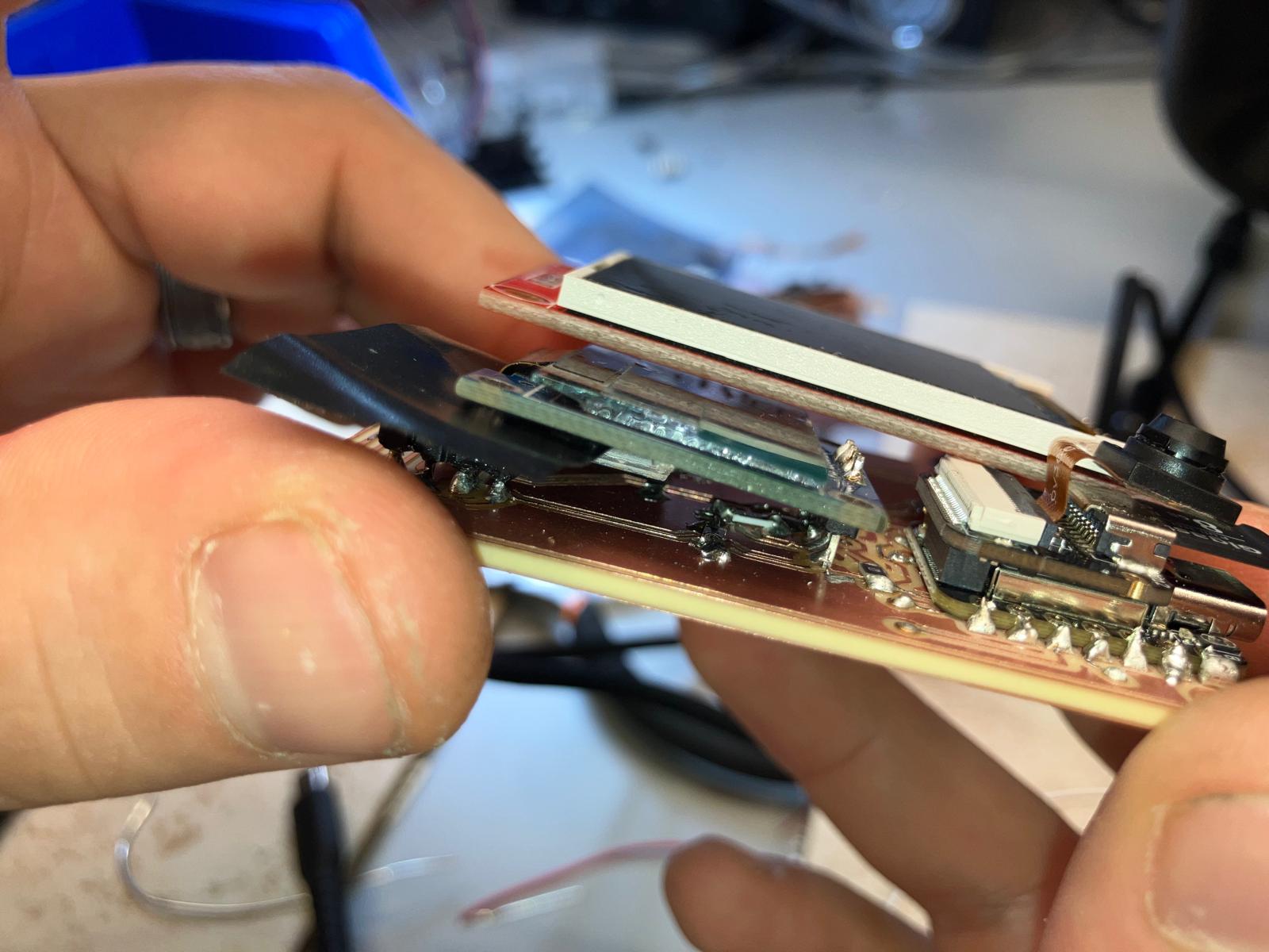
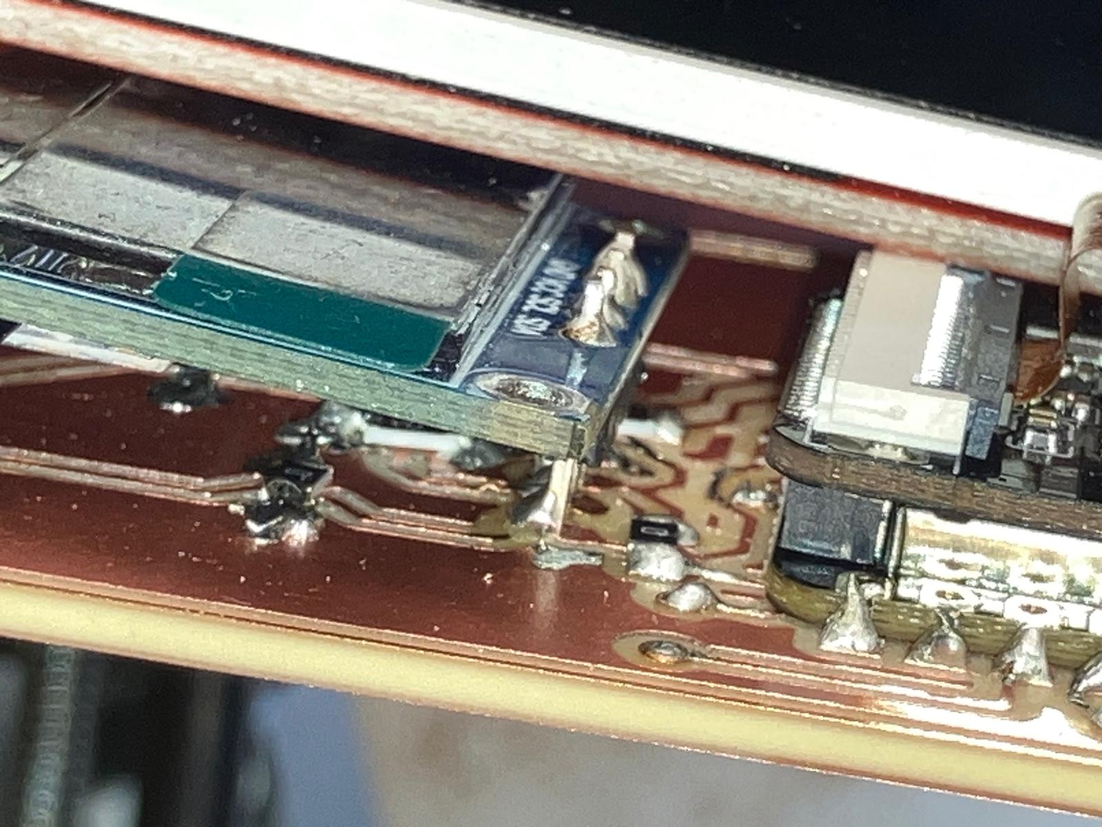
2.1 2D Fabrication: Laser-Cut Enclosure Integration
I attempted to fully close the aging clock watch subsystem using the laser-cut acrylic top plate and printed enclosure. In practice, finite solder height and stacked components meant the acrylic pressed directly on the SDA/SCL traces; under load, the pressure ripped the I²C traces off the board even after successful end-to-end testing. For the final demo, I kept the subsystem open for reliability and prepared a backup pulse oximeter module to rework the board after the full system presentation.
Future electrical spirals will set stricter keep-out zones under fasteners and enclosure pinch points, lower component stack-up height in CAD, and route critical buses away from mechanical interfaces. The current integration still validates the fit envelope and cable-routing strategy, and will be re-closed once replacement boards and sensors are available.
For future iterations, see the consolidated electrical design and integration notes on the final project fabrication section and the updated Bill of Materials for enclosure and sensor stack-up choices.
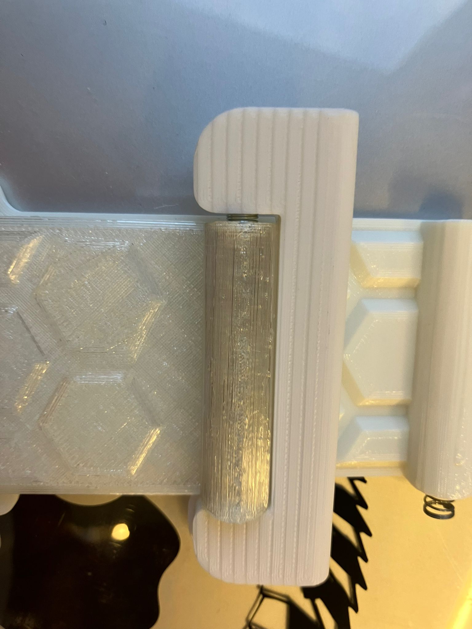
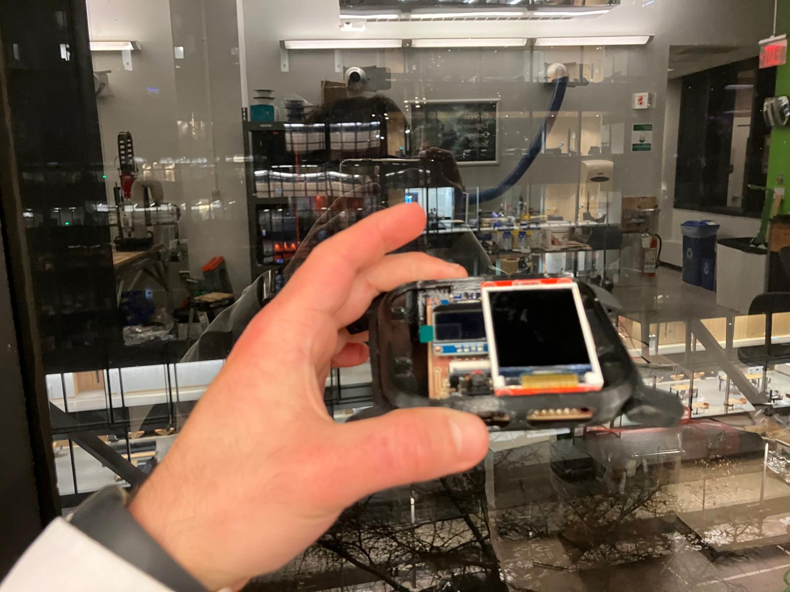
2.2 3D Printing: Rigid Clips and Flexible Bands
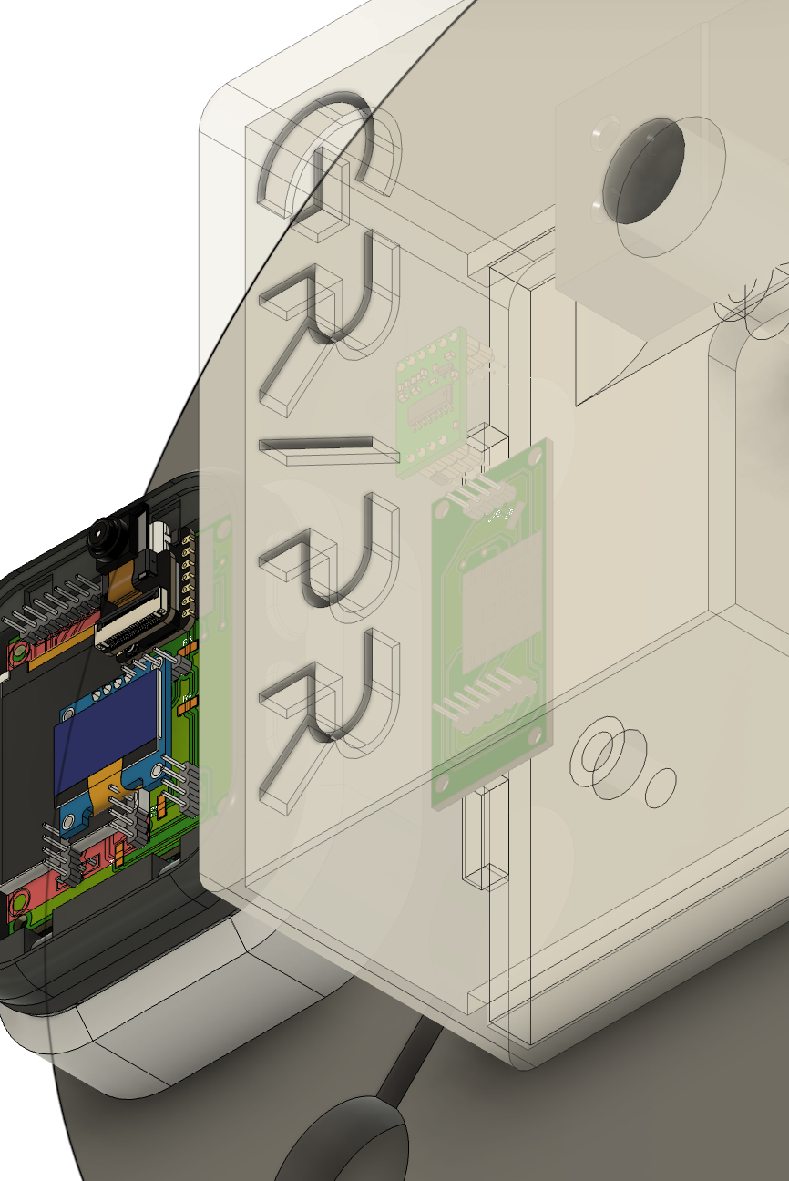
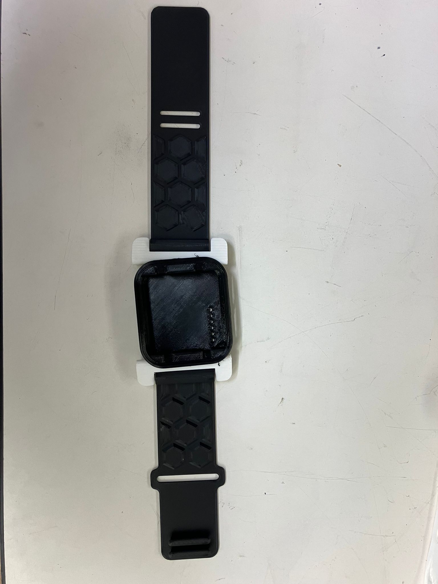
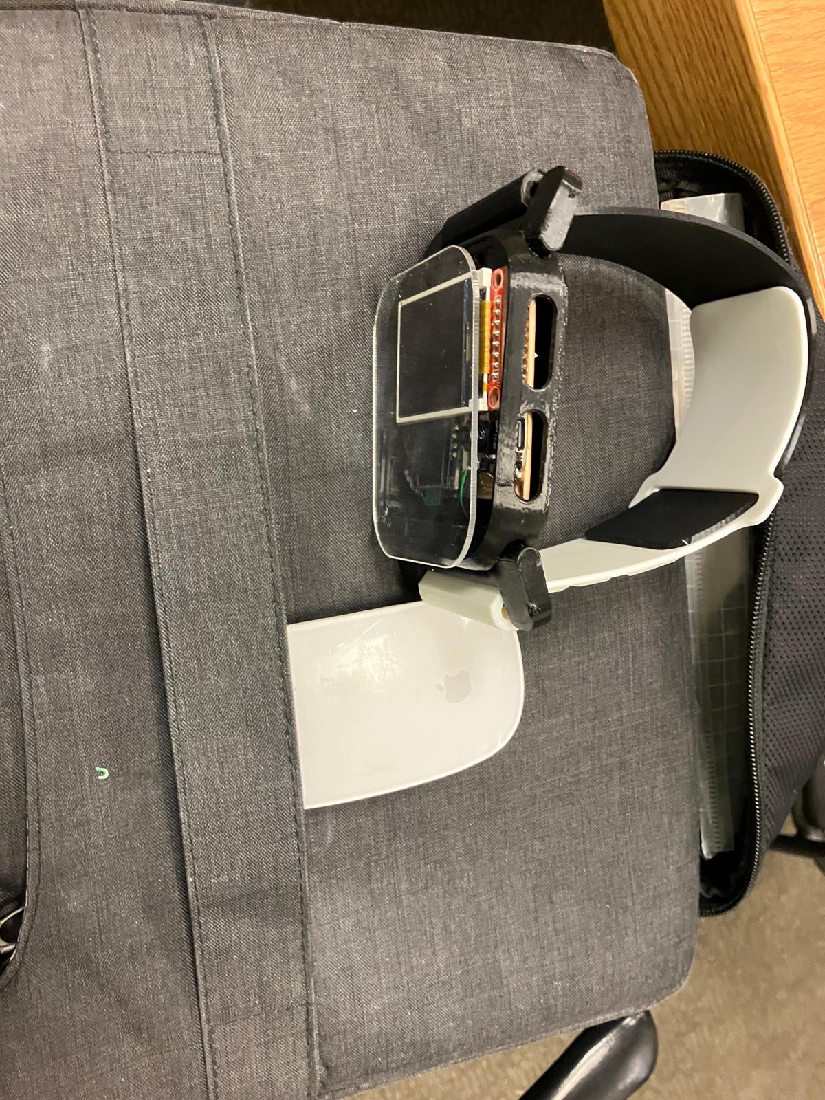
To mount the bands inside the watch clip, I drilled precise holes and inserted inward-facing bolts that clamp into printed TPU clips. TPU provides just enough flexibility and toughness for this fastening strategy, whereas a similar approach would easily tear a silicone band. In the next spiral, the mechanics of the clip will be redesigned so the silicone band experiences distributed compression instead of point loads from metal hardware.
The integrated system view below shows how the TPU band, watch body, and electronics stack come together around the wrist, and serves as the mechanical reference for a future fully cast silicone band with embedded reinforcement.
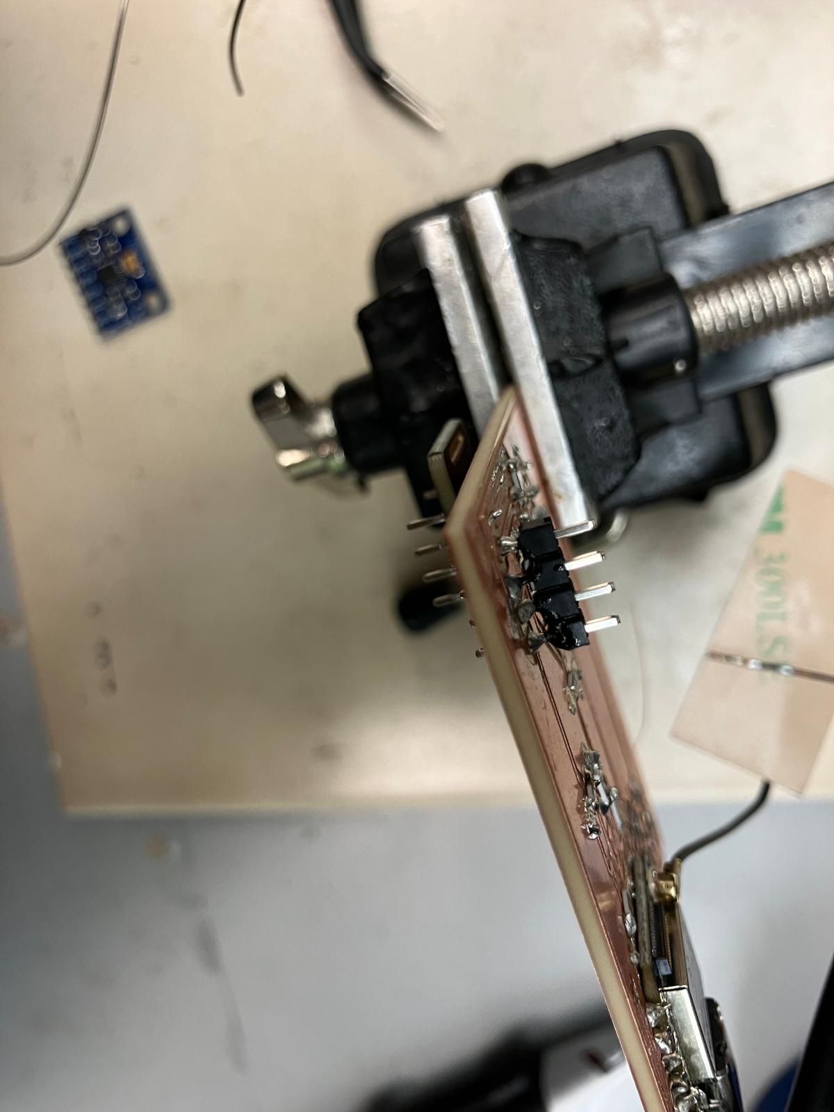
2.3 Soldering and Testing Single and Double-Sided Boards
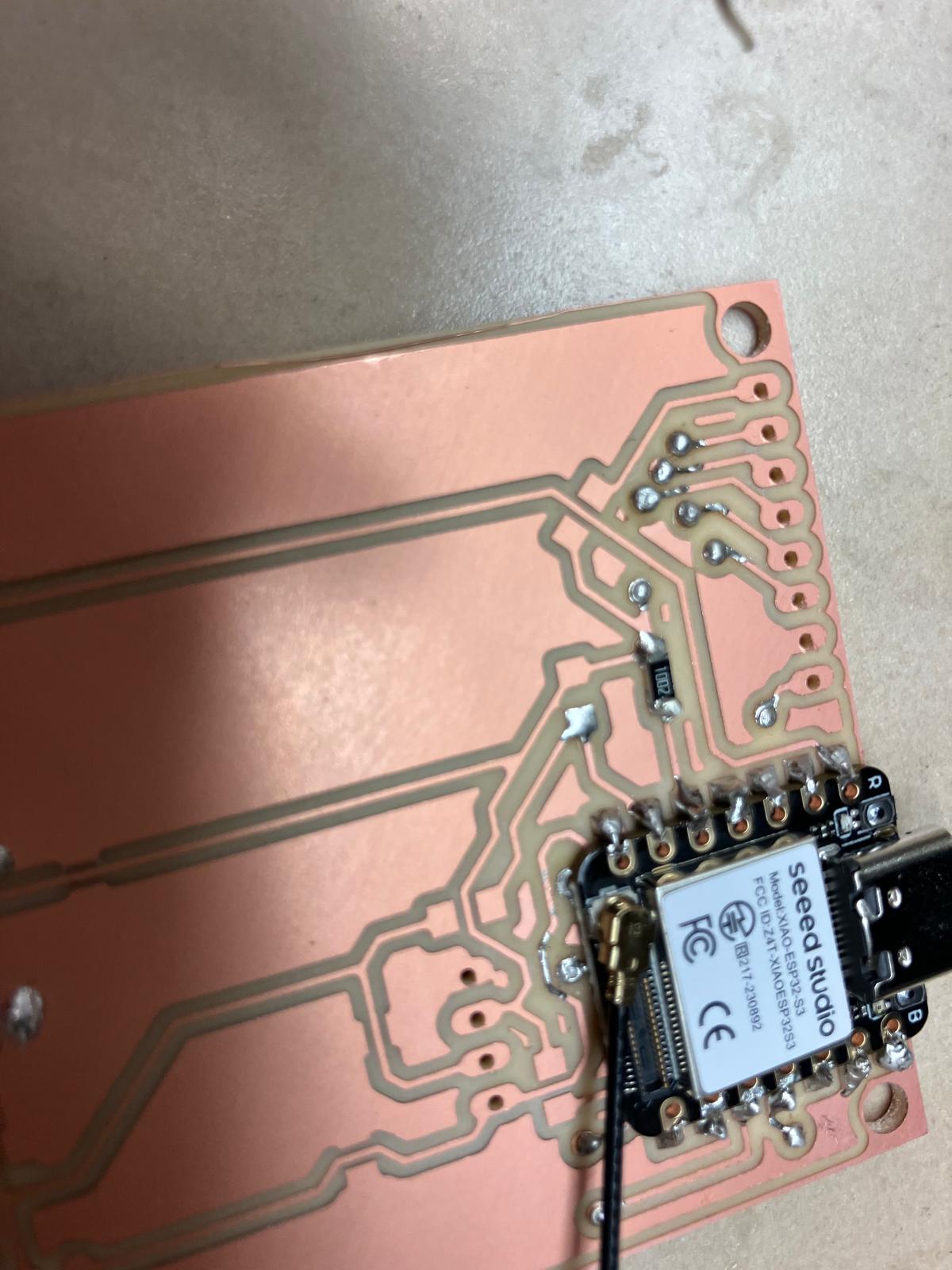
Both the aging clock and MirrorAge boards are double-sided with plated through-rivets. I followed a consistent, compact assembly order: (1) install and flare rivets, (2) solder the microcontroller, (3) place and solder passives, then (4) populate and test input/output devices. The media below document that workflow step by step.
Rivet Installation (Plated Through-Holes)
- Place a rivet into each via from the front side of the board.
- Flip the board carefully using tweezers so rivets stay seated.
- Use the thin flaring tool and light hammer taps to open each rivet.
- Follow with the thicker forming tool to fully set the rivet head.
- Inspect every connection to confirm clean, symmetric flares with no wobble.
Component Placement and Compact Soldering
After through-connection, I placed the microcontroller and passives as flat as possible to preserve headroom inside the enclosure. Headers were soldered last, from both the top and side, to keep cable strain away from delicate pads.
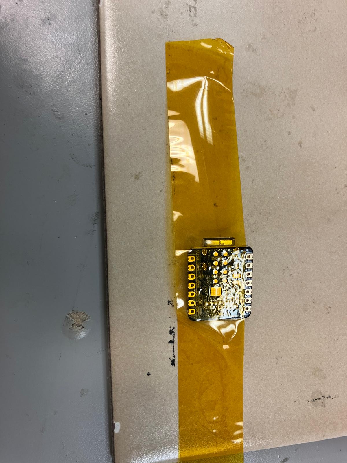
Taped Microcontroller Soldering Technique
To keep the XIAO footprint perfectly flat over the rivets, I used Kapton tape as a temporary stencil: the tape masked exposed copper around the footprint so I could drag-solder the castellated edges without flooding nearby vias. Once the joints were complete, the tape peeled away cleanly, leaving the board ready for final inspection.
Serial Bring-Up: Sensor-by-Sensor Testing
After soldering, I brought each sensor up sequentially to isolate any issues. The pulse oximeter, accelerometer, OLED, and TFT were each verified individually over serial before enabling the full integrated sketch.
All boards passed short-circuit checks and per-sensor serial validation. Remaining electrical risks are limited to load cell hardware quality and long-term connector strain, which are documented for post-demo spirals.
2.4 Molding and Casting
The cast bands are mechanically promising but still need finishing. The edges require additional trimming and sanding, and one edge showed an incomplete fill due to insufficient waxing of the mold. Compared to the TPU prints, the casting material has better compliance and skin feel, and will be the preferred long-term solution once the fastening geometry is iterated.
For this week, I used the printed TPU bands for reliability, while documenting the cast band behavior as a future spiral that aligns with the existing mold designs and material choices.
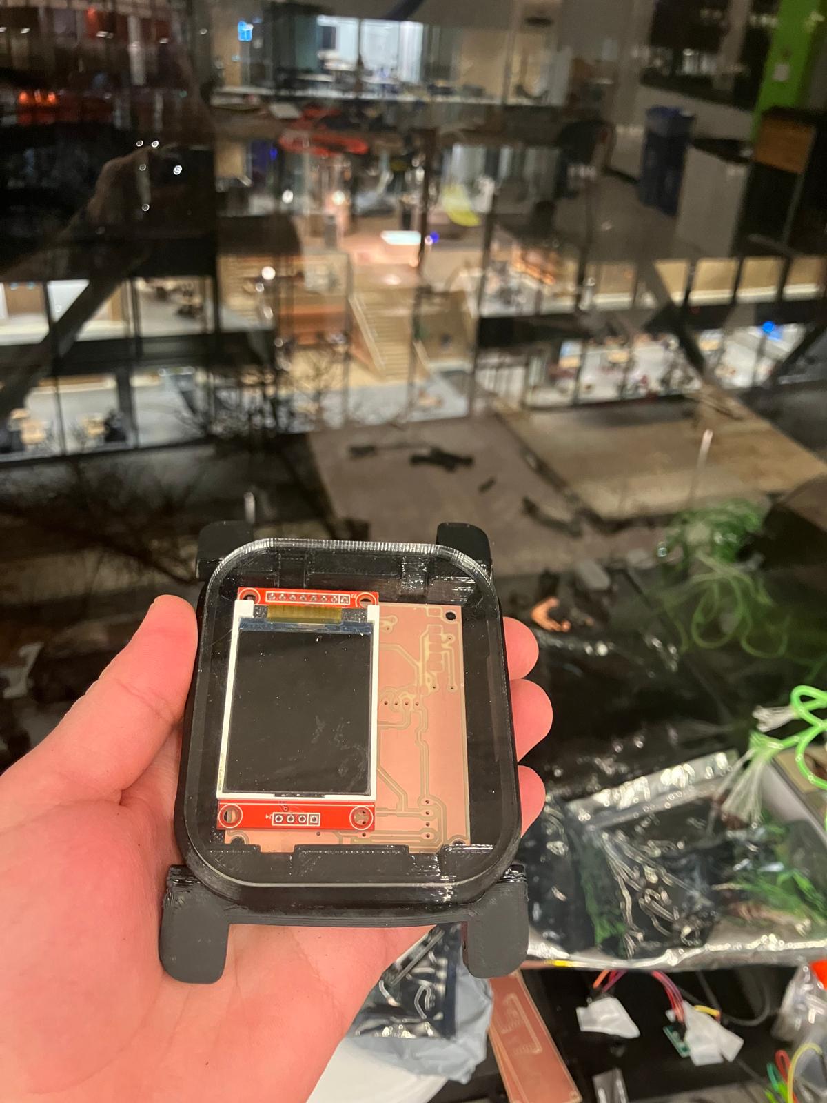
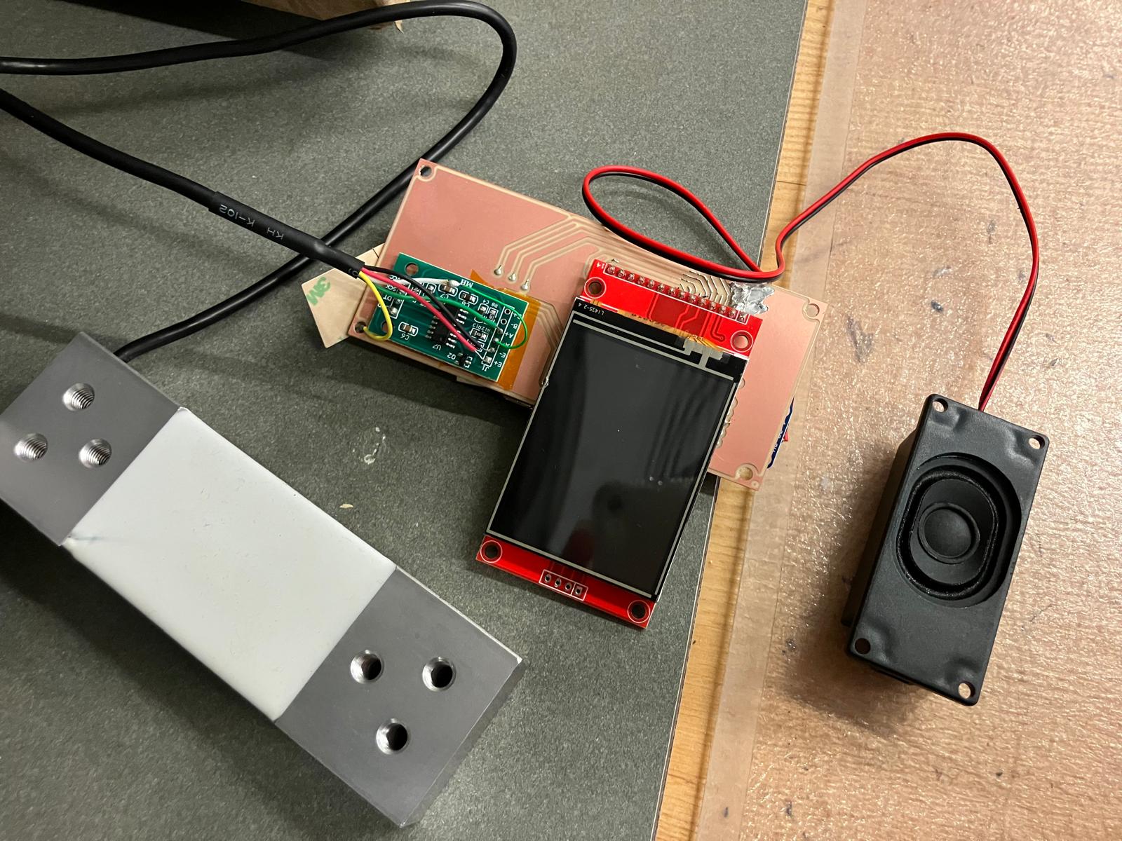
2.5 Aging Clock Subsystem Fabrication
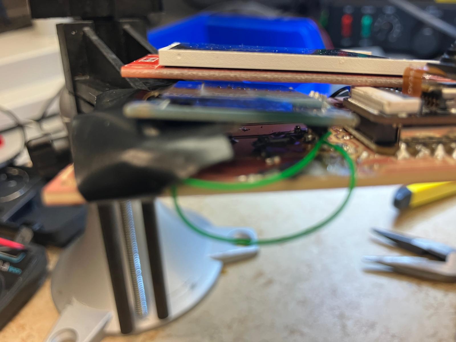
The aging clock subsystem was finalized by cutting and aligning the pulse oximeter opening so the sensor makes direct skin contact while the watch is worn. That opening simultaneously sets the board position inside the enclosure, constraining the stack according to the system-integration CAD.
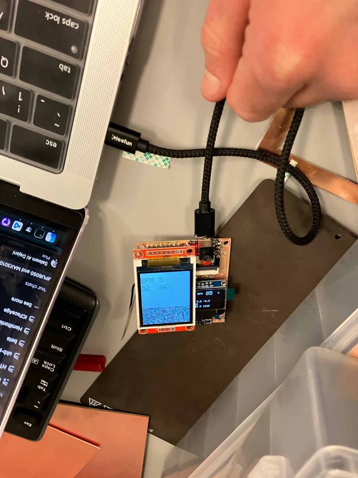
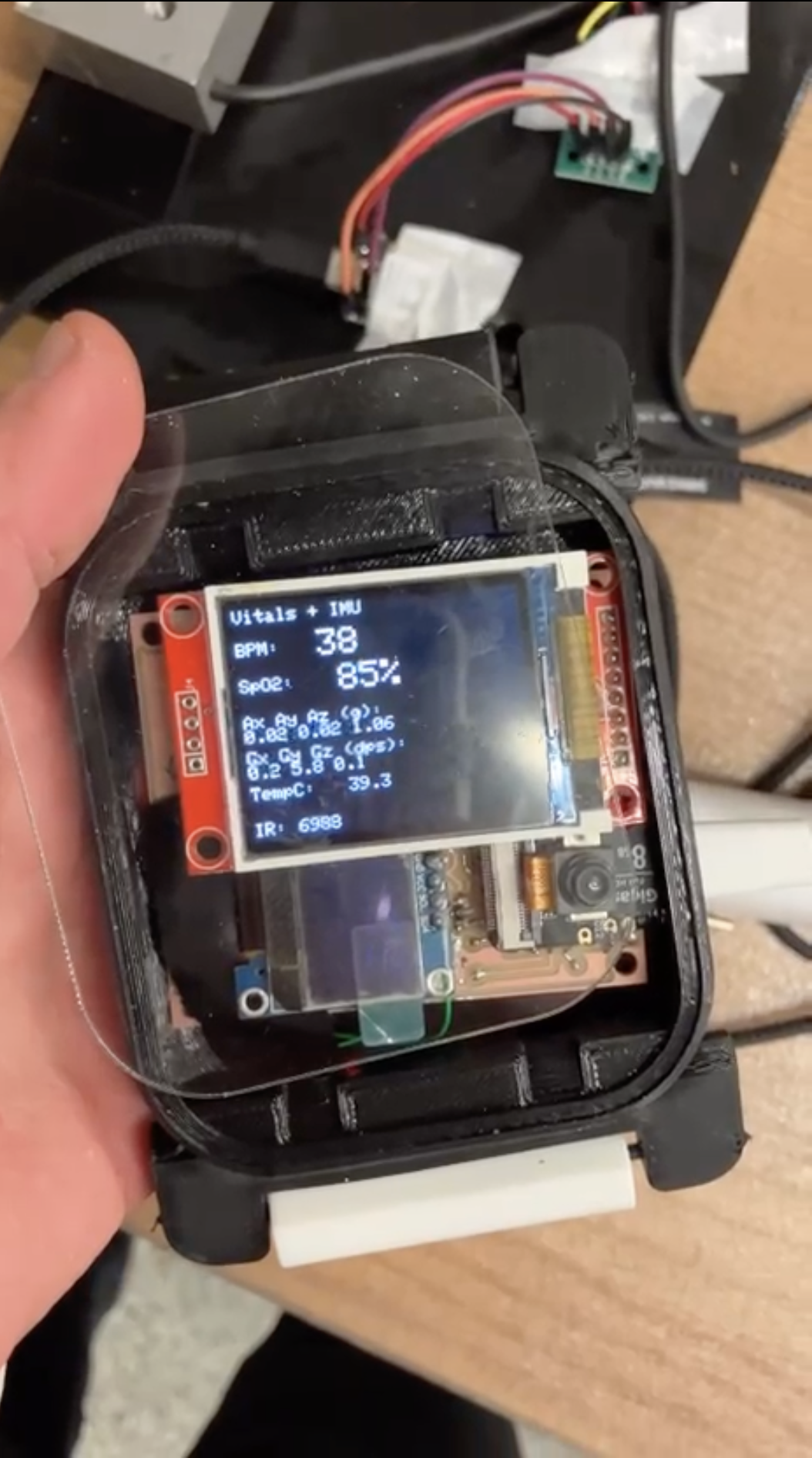
With the TFT watch board, sensors, and acrylic window all integrated, the subsystem mechanically mirrors the final form factor even though the top remains open for this demo to protect the repaired traces.
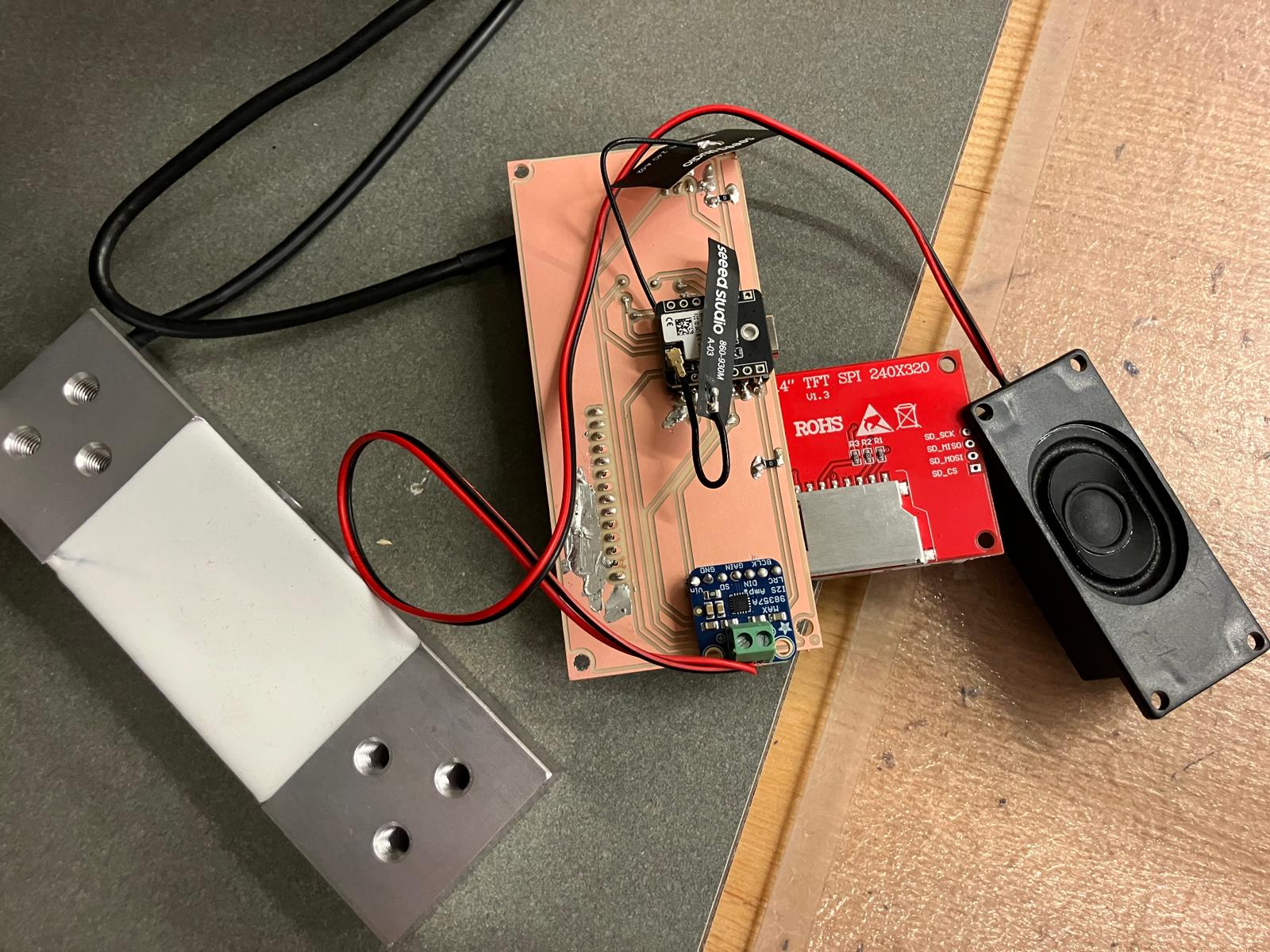
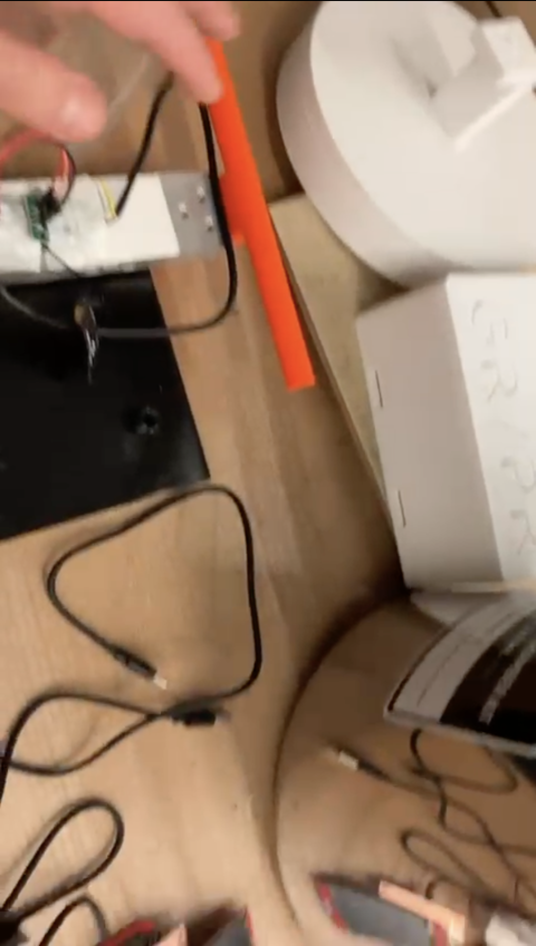
2.6 MirrorAge Subsystem Integration
The grip-strength electronics from Week 12 were mounted on the calibrated working load cell and integrated with the new MirrorAge electronics. Wires from the load cell and amplifier are routed along the structure and strain relieved with a moderate amount of glue to balance robustness with serviceability. The boards sit in their dedicated pockets according to the system-integration CAD, keeping the mechanical and electrical reference frames aligned.
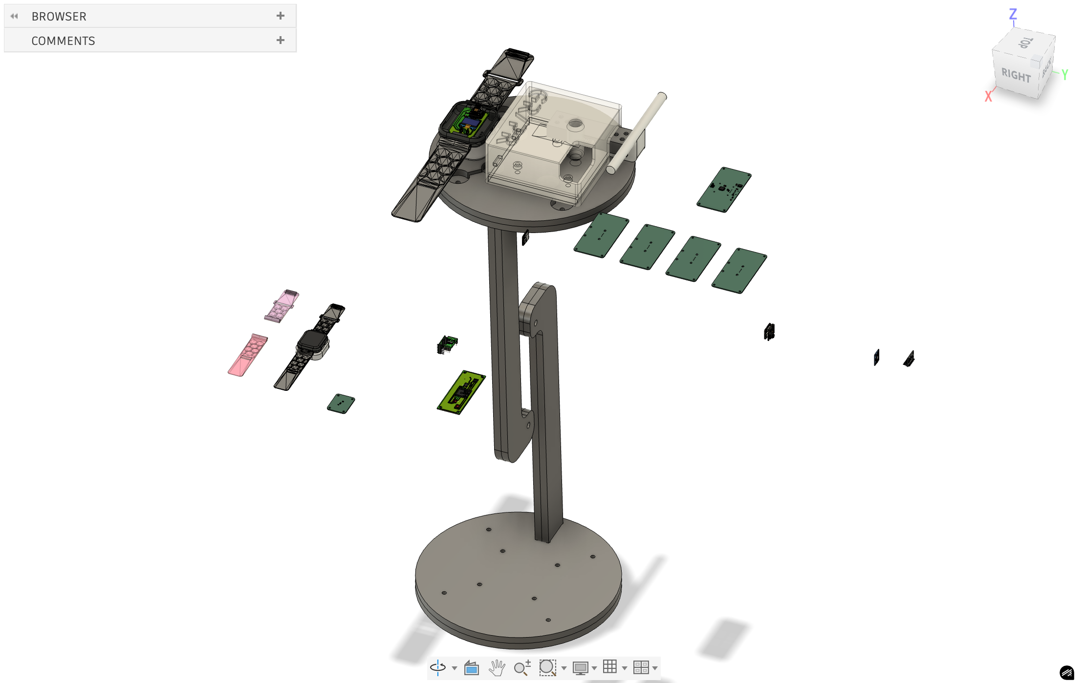
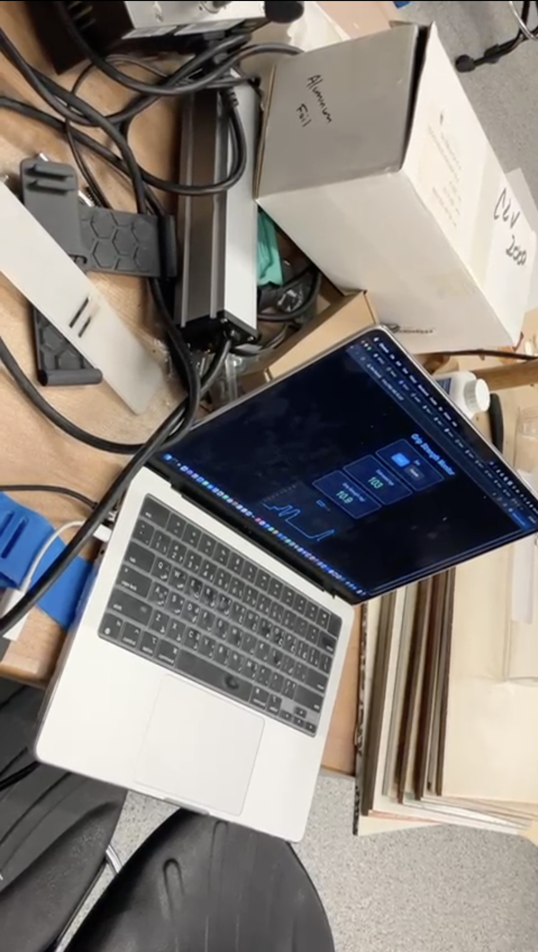
2.7 Full System Integration and Demo Readiness
With both the aging clock and grip-strength subsystems assembled, I brought the entire MirrorAge demo together on the tensegrity table. The videos below show the system running after final debugging, including sensor readouts and synchronized display behavior across the boards.
Day 6: Final Project Masterpiece
Final presentation demonstration of the complete MirrorAge system, showcasing the integrated aging clock and grip-strength subsystems working together in real-time. View final project demo → · See where all HTMAA questions are answered →
This final presentation video demonstrates the complete MirrorAge system in action, featuring both the aging clock watch subsystem and the grip-strength measurement subsystem operating together. The demo showcases real-time sensor readings, synchronized display updates, and the full integration of mechanical, electrical, and software components developed throughout the semester.
1 Minute Video and 1 Slide Summary
Condensed 1-minute video and 1 slide summary showcasing key features and functionality of aging clock device system.
Design Files
Comprehensive table of all design files used in the system integration, organized by category with descriptions and links to their usage locations.
📁 Fusion 360 Files: All Fusion 360 design files are available in the HTMA Fusion team directory under HTMA/2025/EECS/Saleem, organized by the same weeks as the website structure.
| File Name | Description | Category | Used In | Download |
|---|---|---|---|---|
| PCB Design Files | ||||
| agingclock_tft.brd | Aging clock watch board with TFT display integration (pulse oximeter, accelerometer, camera) | PCB Design | Day 2, Day 4 | Download |
| mirrorage.brd | Base MirrorAge amplifier board with load cell interface (HX711) and real-time audio amplifier | PCB Design | Day 2, Day 3 | Download |
| mirrorage_tft.brd | MirrorAge amplifier board with TFT display integration (2.4" ILI9341) | PCB Design | Day 2, Day 3, Day 4 | Download |
| design_xiao.kicad_pcb | KiCad PCB design for XIAO ESP32-S3 base board (non-touch version) | PCB Design | Day 2 | Download |
| design_xiao.kicad_pcb (touch) | KiCad PCB design for XIAO ESP32-S3 with touchscreen support | PCB Design | Day 2 | Download |
| QPAD21.kicad_pcb | KiCad PCB design for QPAD21 board (reference design) | PCB Design | Reference | Download |
| design_micro.kicad_pcb | KiCad PCB design for microcontroller board (reference) | PCB Design | Reference | Download |
| 3D Design Files | ||||
| WatchBody.3mf | Main watch body casing for aging clock subsystem | 3D Model | Day 2, Day 3 | Download |
| Dock.3mf | Dock component for board mounting and electrical connection | 3D Model | Day 2, Day 3 | Download |
| Display Glass.3mf | Display cover component for watch face protection | 3D Model | Day 2 | Download |
| Bands.3mf | Watch band components for wearable attachment | 3D Model | Day 2, Day 3 | Download |
| band-a-scaled.3mf | Scaled band component A for casting molds | 3D Model | Day 4 | Download |
| band-b-scaled.3mf | Scaled band component B for casting molds | 3D Model | Day 4 | Download |
| watchband_clip.3mf | Watch band clip component for secure attachment | 3D Model | Day 3, Day 4 | Download |
| watch v2.5-whole v1.3mf | Complete watch assembly model version 2.5 | 3D Model | Day 1 | Download |
| band-a-mold.3mf | 3D printable mold A for band casting | 3D Model | Day 4 | Download |
| band-b-mold.3mf | 3D printable mold B for band casting | 3D Model | Day 4 | Download |
| band-a-mold-print-10p.3mf | Optimized mold A print file with 10% infill | 3D Model | Day 4 | Download |
| band-b-mold-print-10p.3mf | Optimized mold B print file with 10% infill | 3D Model | Day 4 | Download |
| 2D Design Files | ||||
| square_2_final.svg | Final laser cutting design for display cover (1.35mm acrylic) | 2D Design | Day 4 | Download |
| square_2.svg | Intermediate laser cutting design iteration | 2D Design | Day 2 | Download |
| square.svg | Initial laser cutting design for display cover | 2D Design | Day 2 | Download |
| square_2.dxf | DXF format for laser cutting (intermediate iteration) | 2D Design | Day 2 | Download |
| square.dxf | DXF format for laser cutting (initial design) | 2D Design | Day 2 | Download |
| Code Files | ||||
| blink_ESP32S3.ino | Basic blink test code for ESP32-S3 XIAO | Arduino Code | Testing | Download |
| test_display_ESP32S3.ino | TFT display test code for ESP32-S3 XIAO | Arduino Code | Testing | Download |
| test_touch_ESP32S3.ino | Touchscreen test code for ESP32-S3 XIAO | Arduino Code | Testing | Download |
| test_serial_ESP32S3.ino | Serial communication test code for ESP32-S3 XIAO | Arduino Code | Testing | Download |
| Reference Design Files | ||||
| design_xiao.step | STEP file for XIAO ESP32-S3 mechanical reference | 3D Model | Reference | Download |
| Seeed Studio XIAO-ESP32-S3-Sense.step | STEP file for Seeed Studio XIAO ESP32-S3 Sense board | 3D Model | Reference | Download |
| TFT LCD 2.4 inch ILI9341 touch.step | STEP file for 2.4" ILI9341 TFT display with touch | 3D Model | Reference | Download |
| SSD1306_OLED_Display(128x64).step | STEP file for SSD1306 OLED display reference | 3D Model | Reference | Download |
| MPU6050.stp | STEP file for MPU6050 accelerometer reference | 3D Model | Reference | Download |
| 3006 MAX98357.step | STEP file for MAX98357A amplifier reference | 3D Model | Reference | Download |
| max98357a adafruit.SLDPRT | SolidWorks part file for MAX98357A amplifier reference | 3D Model | Reference | Download |
| apple-watch-se-2nd-gen-band-adapter20251028-1-u4zeat.zip | Apple Watch band adapter design files (ZIP archive) | 3D Model | Reference | Download |
The watch casing and band geometries used in this project were adapted and scaled 2:1 from the open-source MutantW V2 ESP32-S3 smartwatch design. Original reference designs and documentation can be found in the MutantW V2 GitLab project, MutantW V2 Instructables build guide, and Arduino /r/arduino discussion thread.
Bill of Materials (MirrorAge System)
Consolidated bill of materials for the integrated MirrorAge system used in this Week 14 system-integration build. This table mirrors the final project Bill of Materials and is repeated here so readers can cross-reference parts directly from the integration workflows.
For the narrative, project-wide context, see the final project BOM and the per-week line items in the weekly documentation (for example the ReactionAge BOM CSV in Week 2).
Critical Path Analysis
Project management view of the integration schedule, showing task dependencies, critical milestones, and current progress status.
Critical Path Tasks
- CAD model consolidation and system integration design ✓
- PCB design: combine OLED/accelerometer with pulse oximeter ✓
- Demo table integration design with subsystem placement ✓
- PCB design: speaker board with realtime amplifier and TFT (MirrorAge board) ✓
- PCB design: TFT-integrated aging clock board ✓
- Band mold design ✓
- 3D printable cases for board mounting ✓
- TFT display wiring documentation and integration methods ✓
- System schematic documentation (wired and wireless) ✓
- Website documentation updates (Day 1, Day 2, Day 3, Day 4) ✓
- PCB milling: aging clock board milled (with corrections and remilling) ✓
- PCB milling: MirrorAge board base version (remilled after isolation fix) ✓
- PCB milling: MirrorAge TFT board ✓
- PCB milling: TFT-integrated aging clock board (corrected and remilled) ✓
- Component soldering (single- and double-sided boards) ✓
- Band mold printing and casting ✓
- 3D printing of board cases (casing, dock, bands, TPU clips) ✓
- 2D subtractive: laser-cut acrylic display (thinner 1.35mm version) ✓
- Aging clock subsystem assembly (board, TFT, casing integration) ✓
- Physical integration refinements: extra mounting holes, final power-routing harnesses, mirror film application to screen ✓
- Board-level firmware integration for aging clock and MirrorAge boards ✓
- System wiring and I²C bring-up for integrated demo ✓
- WiFi / MQTT network coordination between boards ✓
- Server-level code development and data logging pipelines ✓
- Integrated system testing and validation on tensegrity demo table ✓
- System evaluation and consolidated cost documentation (this page) ✓
- Last documentation review and polishing ✓
- One-minute video production (conception, construction, operation)
- Final summary slide refresh for demo day
Current Status
Subsystem testing and validation, CAD model consolidation, demo table integration design, aging clock PCB design (accelerometer/camera + pulse oximeter), TFT-integrated aging clock board design, MirrorAge board design (base and TFT versions), 3D printing of mechanical components (casing with organic support, dock with brim, TPU bands and clips), laser-cut acrylic display (1.35mm thin version), aging clock board milling (with corrections and remilling), MirrorAge board milling (base and TFT versions), band mold design and casting (MoldStar 30), TFT display wiring documentation with touchscreen integration methods, aging clock subsystem assembly, Day 4 fabrication integration documentation
Refining physical integration (extra mounting, mirror film), extending firmware from working demo to networked IC pipeline, and documenting data-integration methods (serial, WiFi, MQTT) for future spirals.
WiFi/MQTT network setup, final IC scoring integration, one-minute video, and last presentation/documentation touches.
Buffer Days (Saturday & Sunday)
Tasks that cannot be completed during scheduled weekdays will be shifted to Saturday and Sunday buffer days. This ensures the critical path remains on schedule while allowing flexibility for unexpected delays or additional refinement work.
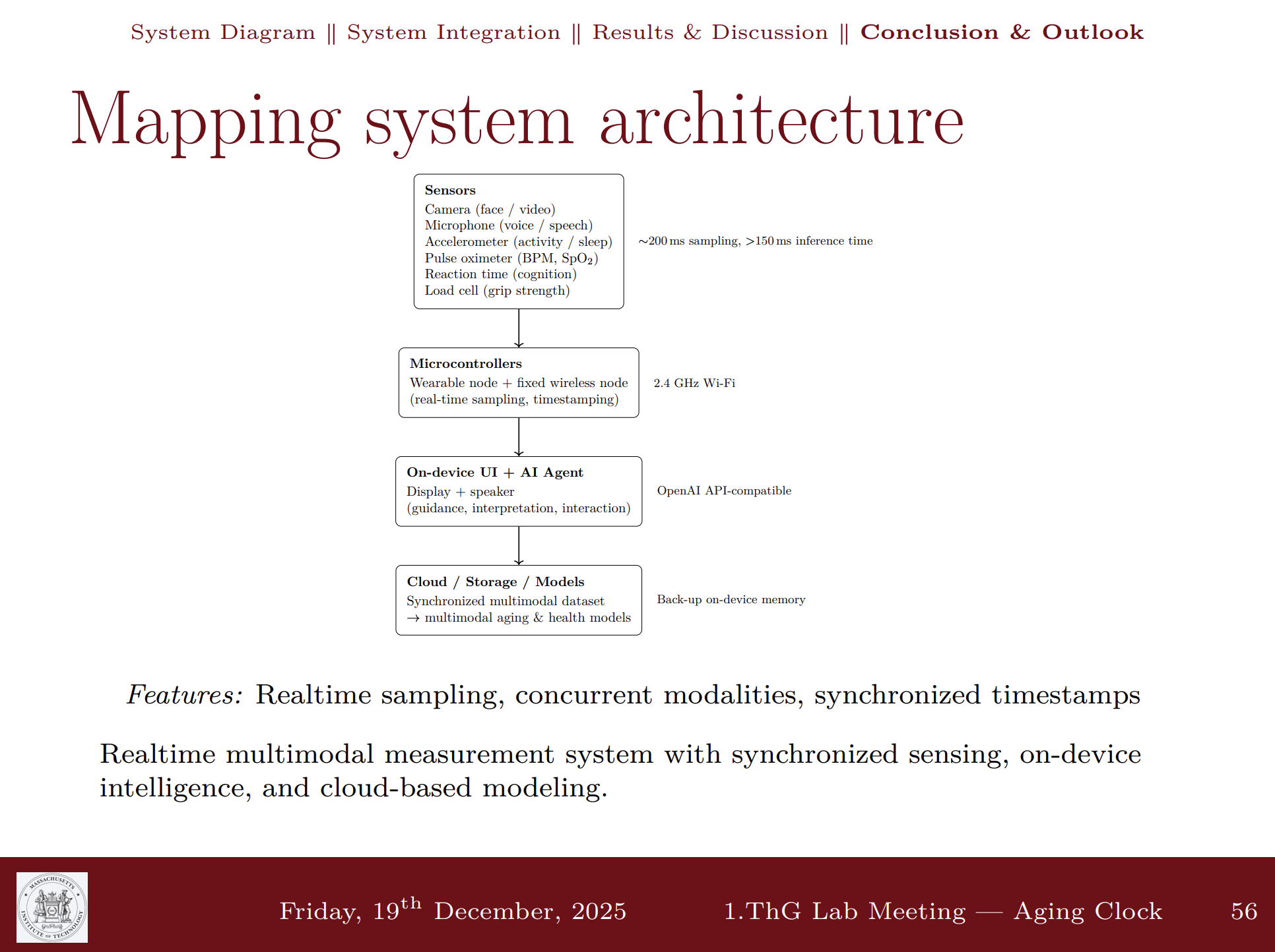
Data Integration Methods in Spiral Development
Progressive development approach for integrating sensor data streams from multiple subsystems, starting with simple serial communication and evolving to wireless network-based architectures.
Method 1: Serial Communication (Easiest)
Direct serial communication through USB cable from computer to microcontroller, using PySerial to stream data. This provides the simplest initial integration path for rapid prototyping and debugging.
- USB cable connection from computer to ESP32-S3 microcontroller
- PySerial library for Python-based data streaming
- Arduino Serial functions for microcontroller-side communication
Method 2: WiFi Client Architecture (Second Easiest)
Configure all microcontrollers as WiFi clients that stream data to a flash web server. This enables wireless communication while maintaining a centralized data aggregation point.
- All ESP32-S3 boards configured as WiFi clients on the same network
- Central web server (initially laptop-hosted) receives data streams
- WiFiClient::write() functions for data transmission
Method 3: MQTT Protocol (Advanced)
Message Queuing Telemetry Transport (MQTT) provides a lightweight, publish-subscribe messaging protocol ideal for IoT device communication. This approach enables decentralized data exchange between all MirrorAge subsystems, allowing each board to publish sensor data and subscribe to relevant topics for coordinated system behavior.
Initial development and testing will use a laptop-hosted MQTT broker. In a later development spiral, the server will be migrated to a dedicated Raspberry Pi Zero or Raspberry Pi 5 for standalone operation and improved system portability. Paho MQTT library has been successfully tested for ESP32-S3 implementation.
Week 14 System Integration Code
The core firmware used during Week 14 for the aging clock watch and grip-strength subsystem is available below as both .ino source files and downloadable .zip archives.
These sketches currently run over simple serial/I²C links and will be extended in future spirals to stream data over WiFi/MQTT to the multimodal IC pipeline. The XIAO boards and TFT displays
also include SD card support for local backup storage once that code path is integrated.
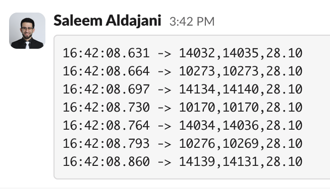
aging_clock.ino initializes the MAX30102 pulse oximeter and IMU on the I²C bus, reads heart-rate and motion data, and prints structured serial lines for debugging.
The main loop continuously:
- checks for new sensor samples (IR, RED, BPM, acceleration)
- updates rolling averages / thresholds for stability
- writes comma-separated values to
Serialfor logging or GUI visualization
Download:
view aging_clock.ino ·
download aging_clock.zip
aging_clock_oled.ino builds on the base sketch by adding an SSD1306 OLED UI. Pseudocode:
- setup: init I²C, MAX30102, IMU, and SSD1306 display
- loop: read sensor values, compute BPM/SpO₂ estimate, and render numeric values + simple icons on the OLED
- send the same values over
Serialfor logging
Download:
view aging_clock_oled.ino ·
download aging_clock_oled.zip
aging_clock_tft.ino migrates the watch UI to a 1.8″ ST7735 TFT. The sketch:
- configures SPI pins according to the TFT wiring table in Day 2/3
- initializes the TFT with a dark theme and large fonts
- reads BPM/SpO₂ and motion, then draws large, legible numbers and status icons on screen
Download:
view aging_clock_tft.ino ·
download aging_clock_tft.zip
aging_clock_tft_slow.ino is a debug variant that intentionally slows down screen refresh to make timing and flicker issues visible. Conceptually:
- same sensor reads and TFT layout as the fast version
- adds deliberate delays or only redraws at fixed intervals (e.g. once per second)
- prints extra timing information over
Serialto tune update rates
Download:
view aging_clock_tft_slow.ino ·
download aging_clock_tft_slow.zip
loadcell_gui.ino drives the CZL601AC + HX711 grip-strength subsystem and streams data to a serial/GUI plot. High-level flow:
- calibrate HX711 with tare and known weights
- in the loop, read raw counts, apply calibration to get force
- print values in a GUI-friendly format (e.g. CSV or JSON lines) for plotting or web visualizations
Download:
view loadcell_gui.ino ·
download loadcell_gui.zip
Additional sketches (e.g., WiFi/MQTT clients, SD-card logging for the XIAO ESP32S3 and TFT shields) will be integrated in a future spiral once the serial and WiFi baselines are fully stabilized.
Resources and Documentation
Spiral Development Approach
Development will progress through these methods in order of complexity, starting with serial communication for rapid prototyping, then moving to WiFi client architecture for wireless operation, and finally implementing MQTT for advanced decentralized communication. Each subsystem board (pulse oximeter, OLED/accelerometer, speaker/amplifier, load cell) will be integrated progressively, enabling:
- Incremental complexity management and early validation
- Decoupled communication between subsystems
- Real-time data streaming from multiple sensors
- Scalable architecture for adding new sensor modules
- Flexible server deployment (laptop → Raspberry Pi migration path)
Reflections & Learnings
Reflections and key learnings from the final project integration week.
Key Points
- System integration only works when mechanical envelopes, electrical robustness, and firmware are designed together and validated in short spirals.
- Day-by-day planning and a clearly tracked critical path made it possible to finish fabrication, integration, and documentation on time.
- Modular PCB and enclosure design allowed me to remill, resolder, and swap boards (including backup pulse oximeter modules) without restarting the whole system.
- Careful documentation of failures—like ripped SDA/SCL traces, noisy load cells, and serial upload errors—directly improved the final wiring, strain relief, and bring-up process.
- Collaborators, late-night debugging, and AI-assisted writing were all part of getting from a set of subsystems to a fully integrated, demo-ready MirrorAge system.
Contributions
Acknowledgments for contributions and collaborations during the final project week.
- Anthony Pennes — for helping at every step of the way, including patient late-night debugging sessions and a major final-hour assist at around 2 a.m. that kept the integrated demo on track.
- Quentin — for jumping in whenever he had time, suggesting the bolt-based fastening approach for the bands, and providing steady encouragement throughout the integration week.
- Mariam — for offering a replacement pulse oximeter in the final hour of debugging after my backup was lost and the board broke during integration, with a replacement order already placed and arriving by Tuesday of this week.
Ethical AI Use
Documentation of AI-assisted tasks and tools used during the final project integration week.
📋 General Guidelines: See General Commands for Cursor on the homepage for standard guidelines and commands used consistently throughout documentation development.
Cursor · Project Plan & Weekly Schedule (Day 0)
Comprehensive Cursor AI assistance for outlining the project plan and weekly schedule, including documentation structure, content organization, systematic updates across all week pages and the final project page, media integration, and summary generation workflows.
Cursor · Week 14 & Final Project Documentation
End-of-semester Cursor AI assistance for Week 14 integration and finalproject.html updates, including sensor bring-up captions, molding/casting cross-links, Answering Questions anchors, and Ethical AI use summaries.
The full conversation is preserved as a markdown transcript and a styled HTML view generated with scripts/md_to_html_converter.py.
Cursor · Final Project and Week 14 HTML Images
Cursor AI assistance for updating finalproject.html and week14.html, including adding the summary slide side-by-side with the one-minute video, and reorganizing the Serial Bring-Up sensor testing section with new image order and combined captions. The full conversation is preserved as a markdown transcript and a styled HTML view generated with scripts/md_to_html_converter.py.
Cursor · MutantW V2 Smartwatch Resources
Cursor AI assistance specifically for gathering and documenting open-source MutantW V2 ESP32-S3 smartwatch resources, including links to the GitLab project, Instructables guide, and Arduino community discussion. This session supported the ethical attribution of the 2:1 scaled watch casing and band designs used in the Week 14 3D printing and design-files sections.
The full conversation is archived as a markdown transcript and a styled HTML page generated with scripts/md_to_html_converter.py.
Cursor · Project Integration Updates (Day 1)
Cursor AI assistance for Week 14 Day 1 project integration updates, including design integration documentation and initial system integration planning.
Cursor · Project Integration Updates (Day 2)
Cursor AI assistance for Week 14 project integration updates, including Day 2 electrical and mechanical integration documentation, data integration methods refinement, and critical path analysis updates.
Cursor · Electrical Integration and Fabrication (Day 3)
Cursor AI assistance for Week 14 Day 3 electrical integration and fabrication documentation, including TFT display wiring documentation, board design updates, fabrication integration methods, and Day 3 content updates.
Cursor · Week 14 Project Updates (Day 4)
Cursor AI assistance for Week 14 project integration updates, including Day 4 electrical and mechanical integration documentation, TFT display wiring documentation, board design updates, fabrication integration methods, design files table creation, and comprehensive Day 4 content updates.
Cursor · Final Project Documentation and Integration (Day 5)
Cursor AI assistance for final MirrorAge documentation and system integration, including Day 5 full-system integration write-up, Bill of Materials synchronization between Week 14 and the final project page, critical path updates, and code documentation for the aging clock and load-cell subsystems.
Cursor · System Integration Day 5 & 6
Cursor AI assistance for Day 5 and Day 6 system integration documentation, final system assembly, and presentation preparation.
ChatGPT · Code Development
ChatGPT assistance for firmware development and debugging of the aging clock and load cell subsystems, including sensor integration, display drivers, and data processing algorithms.
Aging Clock Code Development
ChatGPT assistance for developing the aging clock firmware, including MAX30102 pulse oximeter integration, MPU6050 accelerometer readings, TFT display drivers, and sensor data processing algorithms.
💬 View ConversationLoad Cell Code Development
ChatGPT assistance for developing the load cell firmware, including HX711 amplifier integration, calibration routines, force measurement algorithms, and TFT display visualization for grip-strength data.
💬 View ConversationChatGPT · Video Planning
ChatGPT assistance for planning the one-minute video demonstration of the MirrorAge system, including script development, key feature selection, narrative structure, and video production guidelines to showcase the integrated aging clock and grip-strength subsystems effectively.
ChatGPT · One Slide Summary Development
ChatGPT assistance for developing the one-slide summary based on email exchange with Prof. Vadim Gladyshev, including distilling key project achievements, technical highlights, and system integration outcomes into a concise visual summary format for the final project presentation.