Final Project
Aging Clock · HTMAA 2025
Project Highlights
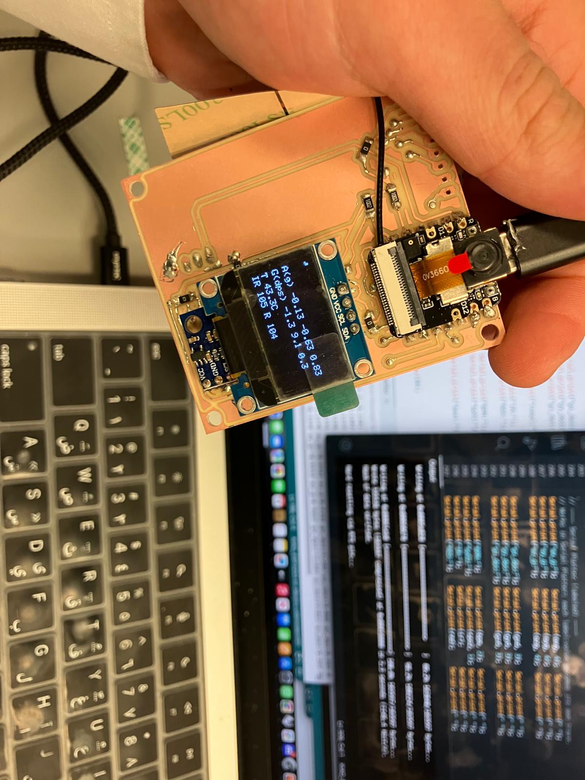
Camera Works!
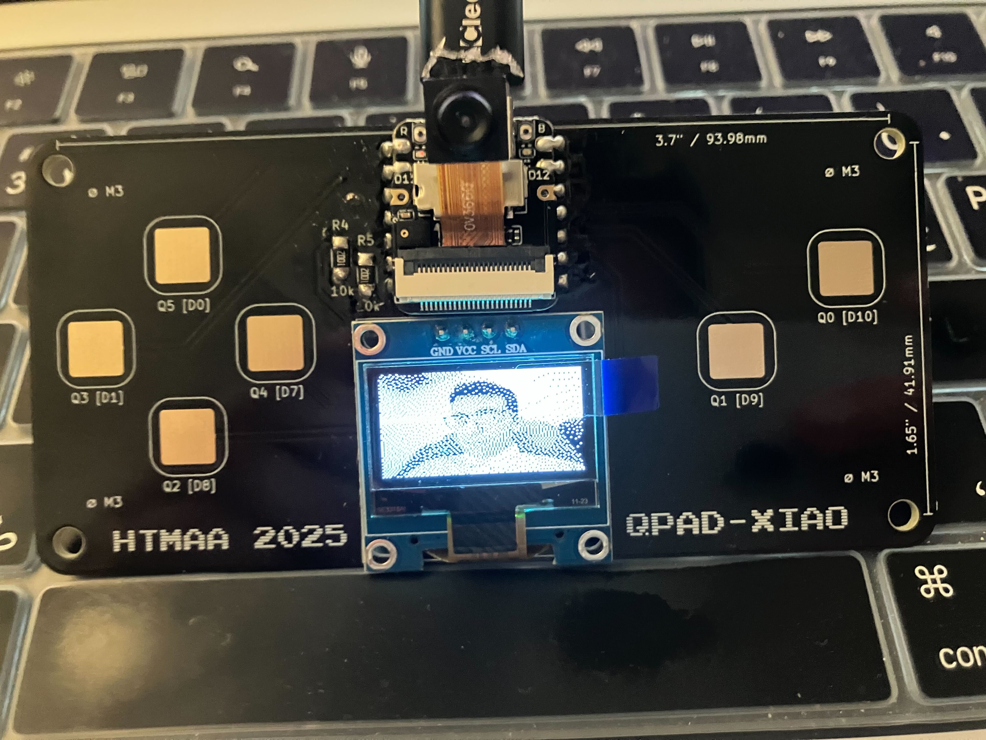
XIAO ESP32S3 camera successfully captures and displays images on OLED screen using Floyd-Steinberg dithering
Vision Board
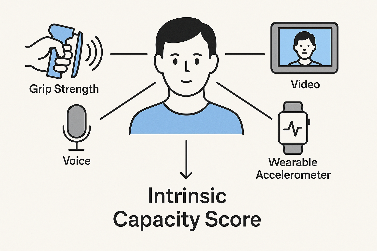
Conceptual visualization of the multimodal intrinsic capacity assessment system integrating grip strength, voice analysis, facial recognition, video motion capture, reaction time measurement, and wearable accelerometer data.
Intrinsic Capacity (IC) Coverage by Digital Biomarkers
✅ Strong coverage | 🔸 Partial/indirect | ❌ Not covered | View full table →
Multimodal IC Pipeline
Weekly System Development
Project Presentation
Final Project Spiral Development Model
.png)
Development Approach: Following the spiral model methodology, this final project will iterate through multiple development cycles, each building upon previous work while addressing new requirements and risks.
System Integration Highlights
Key moments from the final system integration week, showcasing the complete MirrorAge system assembly, testing, and presentation.

Midterm Review Checklist
This snapshot covers the subsystems and documentation that will be shown during the midterm review. Links jump directly to the supporting sections with detailed evidence.
- Camera subsystem — Edge inference demos and selfie capture loop.
- ReactionAge module — Latency measurement firmware and UX.
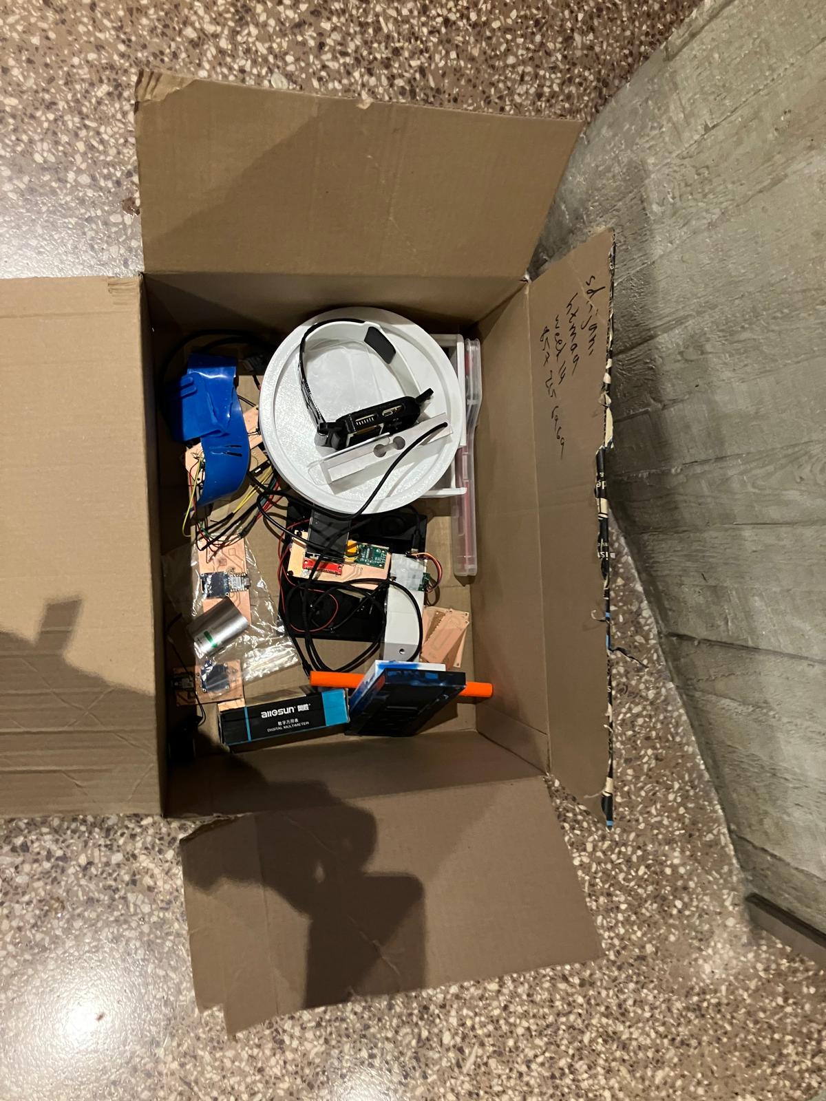
- Grip strength rig — Load cell calibration and enclosure iterations.
- Voice pipeline — Audio capture stack and VoiceAge model notes.
- Integration readiness plan — Outstanding work items and risk mitigation.
- System diagram — refreshed block diagram with annotated sensing, fusion, and feedback flows packaged for the midterm deck.
- Task backlog snapshot — consolidated hardware, firmware, data, UX, and validation checklists that show current status and risk owners.
- Week-of schedule — detailed execution calendar covering evidence capture, documentation polish, dry-run, and buffer windows.
- Instructor meeting hold — Thursday, Nov 12 at 10:00 AM ET reserved via the shared HTMAA midterm review sheet.
Condensed from the Week 8–13 development timeline: each sprint builds toward final integration, mirroring the gantt chart below.
- Week 8 · Output Devices: figuring out wiring for real-time display states.
- Week 9 · Molding & Casting: learn how to cast custom housings and refine structural components.
- Week 10 · Mechanical Design: figure out ergonomic enclosure and calibration fixtures.
- Week 11 · Networking: program BLE/Wi-Fi telemetry and wearable data fusion.
- Week 12 · Interface/App: create mobile UI, cloud bridge, and IC scoring pipeline.
- Week 13 · Final Integration: run validation passes, document results, and prep deployment.
Calendar hold sent for Thursday, Nov 12 at 10:00 AM ET (38-501 conference room) per the shared HTMAA scheduling sheet. Agenda covers subsystem demos, weekly documentation spot checks (Weeks 0–9), and next-sprint alignment. Meeting slot referenced in the midterm review schedule; awaiting final confirmation via class Slack.
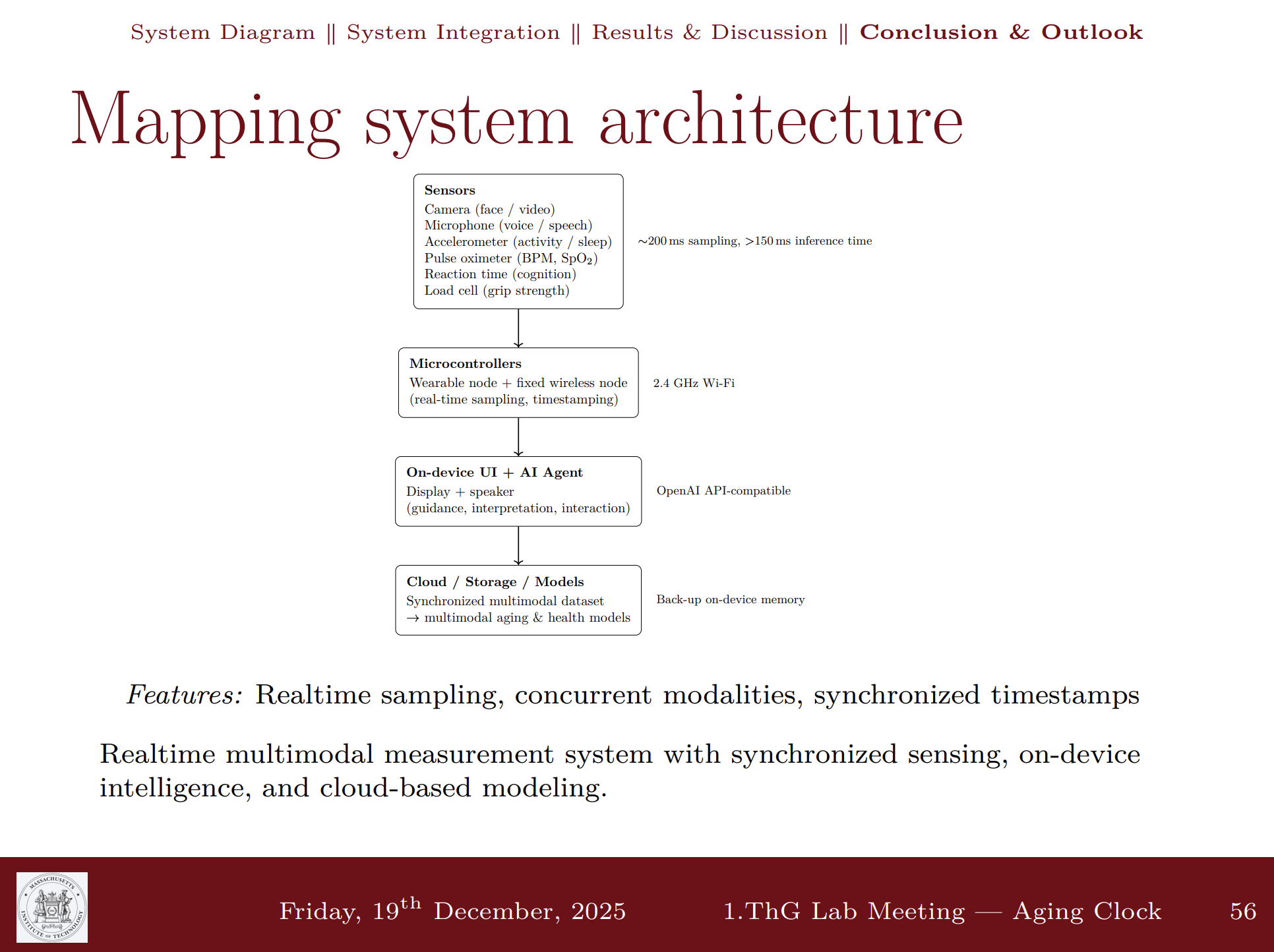
System Architecture
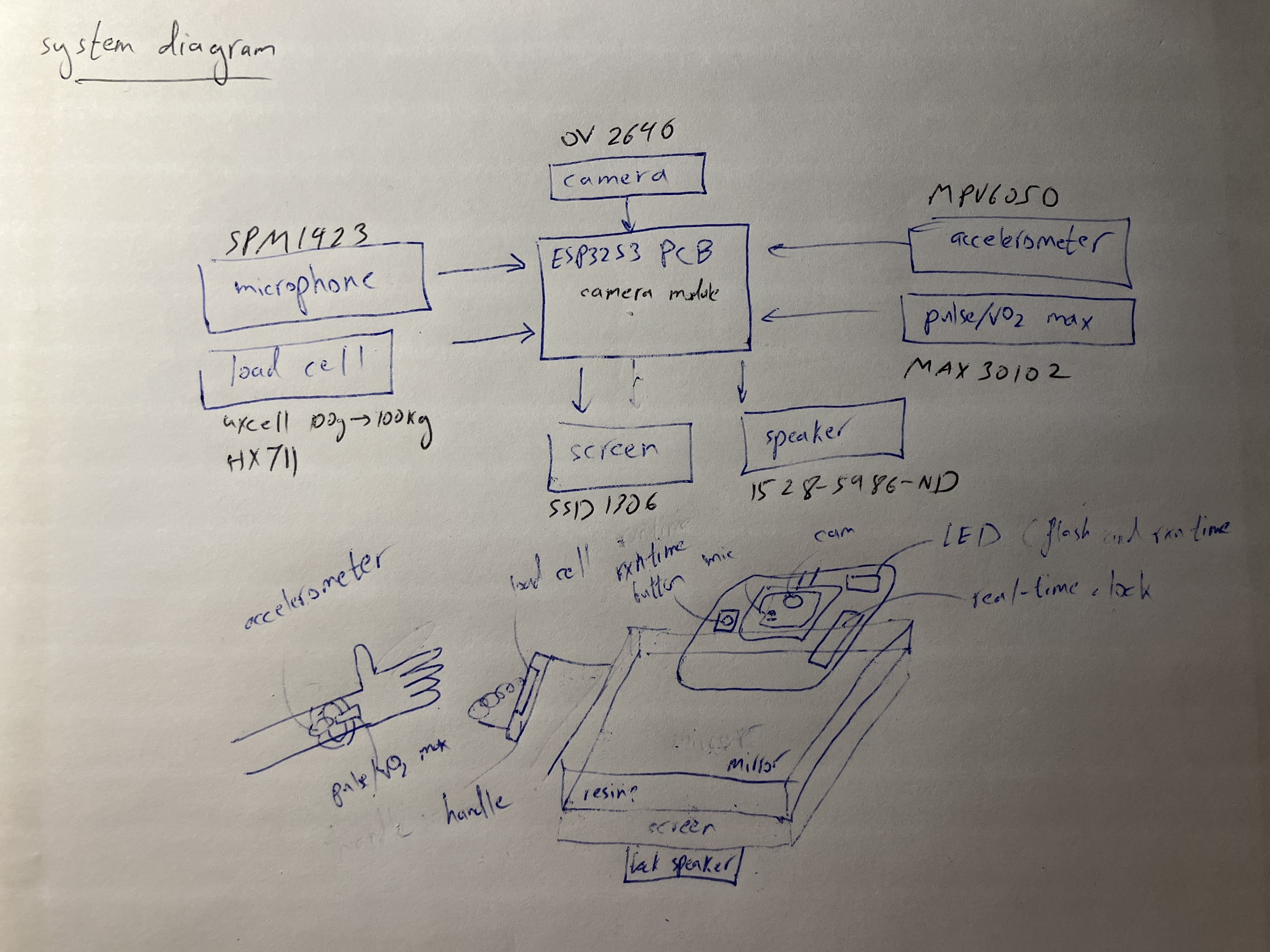
Updated block diagram highlighting the multimodal sensing stack (grip, voice, face, motion, wearables), on-device inference layers, and real-time feedback channels that feed the intrinsic capacity score.
Development Timeline
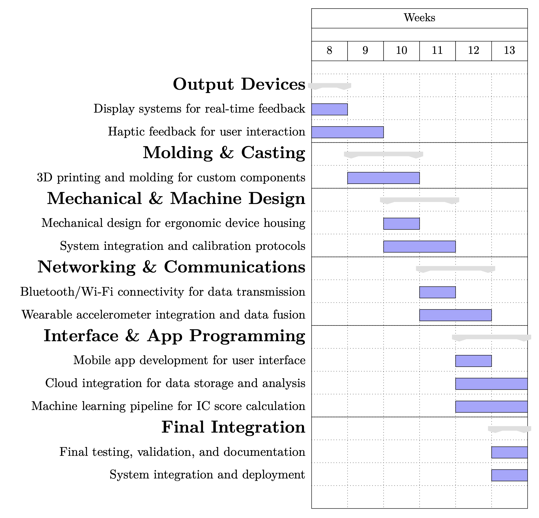
Timeline aligns subsystem sprints with HTMAA milestones: output devices (Week 8), molding and casting (Week 9), mechanical design (Week 10), networking and communications (Week 11), app programming (Week 12), and final integration (Week 13).
Remaining Tasks (Snapshot)
Weeks 0–9 locked in the core subsystems—documentation workflow, cutting and molding for the housing, embedded prototypes for reaction timing, SenseCraft camera inference, and early grip/voice rigs. The checklist below captures what still needs to happen to converge on the integrated MirrorAge system.
- Consolidate grip, voice, camera, reaction-time, and wearable sensor harnesses into the MirrorAge enclosure.
- Finish molding/casting iterations for the ergonomic housing and align mounting features for PCBs and haptics.
- Stabilize onboard inference for SenseCraft vision models and voice-age pipelines on the XIAO ESP32S3.
- Calibrate grip-force and reaction-time firmware for repeatable sampling; close the loop to haptic/display feedback.
- Bring up BLE/Wi-Fi data paths for wearable accelerometer streaming and cloud logging of intrinsic capacity scores.
- Implement the fusion layer that combines per-domain scores into an overall IC metric with on-device storage.
- Finish mobile/web dashboard mockups for user onboarding, data review, and device calibration workflows.
- Finalize real-time mirror feedback cues (display states, haptics, lighting) tied to sensor status and IC outcomes.
- Run end-to-end system tests (sensor capture → fusion → feedback) and document calibration procedures.
- Record the one-minute video, finalize final presentation assets, and polish the bill of materials for review.
Week 14 System Integration Plan
Detailed day-by-day schedule for final system integration, covering design, fabrication, programming, testing, and documentation. This plan outlines the path to completing the MirrorAge system integration and preparing for final presentation. View on Week 14 page →
Week 14 Day-by-Day System Integration Plan

Theme of the Week
The act of bringing something to a conclusion or ending in a decisive manner. The ability to efficiently finish tasks and projects with a goal-oriented mindset.
Wednesday
- Publish system integration plan on website
- Update weekly assignment sections on final project page (weeks 10-13)
- Link final project design files
- Update reflections and learnings
- Update picture of prism holder
- Add final pictures to Slack canvases
- Create schematic between boards (wired and wireless) — updated system diagram on PPT-like page
- Start CAD model of system
- Place final order
- Boards: Combine OLED screen/accelerometer with pulse oximeter board in a new board (maybe upgrade to small TFT as minor)
- Boards: Speaker board with realtime amplifier and TFT (on the load cell fixed board)
- Band: Mold design
- Cases: 3D print mountable cases for the boards
- Integrate designs into final CAD
- Document design
- Finish CAD model of system
Thursday
- Milling boards
- Print mold and cast band
- Print cases
- Solder components on milled boards
- Connect boards with wired (and wireless connection codes)
- Mirror on screen (easy way with the film)
- Document fabrication
Friday
- Board level codes
- Server level codes
- Document codes
- Finish anything else
Saturday
- Demo integrated system
- Test integrated system
- Document testing and evaluation
- Review and complete documentation (list of questions)
- Make the video by collaging documentation
Sunday
- Fill up any gaps
- Prepare demo on tensegrity table
- Finalize 1-slide
- Work on minors
- If done, work on if there's time
Monday Morning
- Transport demo on tensegrity table
- Fill up any gaps
- Work on minors
Specific Tasks to Complete This Week
- CAD model of system
- Speaker board with realtime amplifier
- Combine screen/accelerometer with pulse oximeter board in a new board
- Mold and cast band
- Design and fabricate casing (print)
- Schematic between boards (wired and wireless) — updated system diagram on PPT-like page
- Serial connection between pulse oximeter and tiny blinking heart for BPM (BPM from IR, SpO2 from delta)
- Combine multiple boards on the same WiFi (switching tabs is easy way, board hosting the webpage querying and update or Python-based server somewhere where everything posting data, Raspberry Pi)
- Put+program everything together according to the above (with WiFi for now)
- Mirror on screen (easy way with the film)
- Document evaluations and costs (plus the rest of the list here: project presentation requirements)
- Summary slide and one-minute video for documentation
- Conception
- Construction
- Operation
- Program microphone/speaker
- Fix reaction time delay code
- Program LoRa connection
- Fix OLED plus WiFi issue
- Upgrade to TFT (SPI is very straightforward, design board with either SPI or OLED connection)
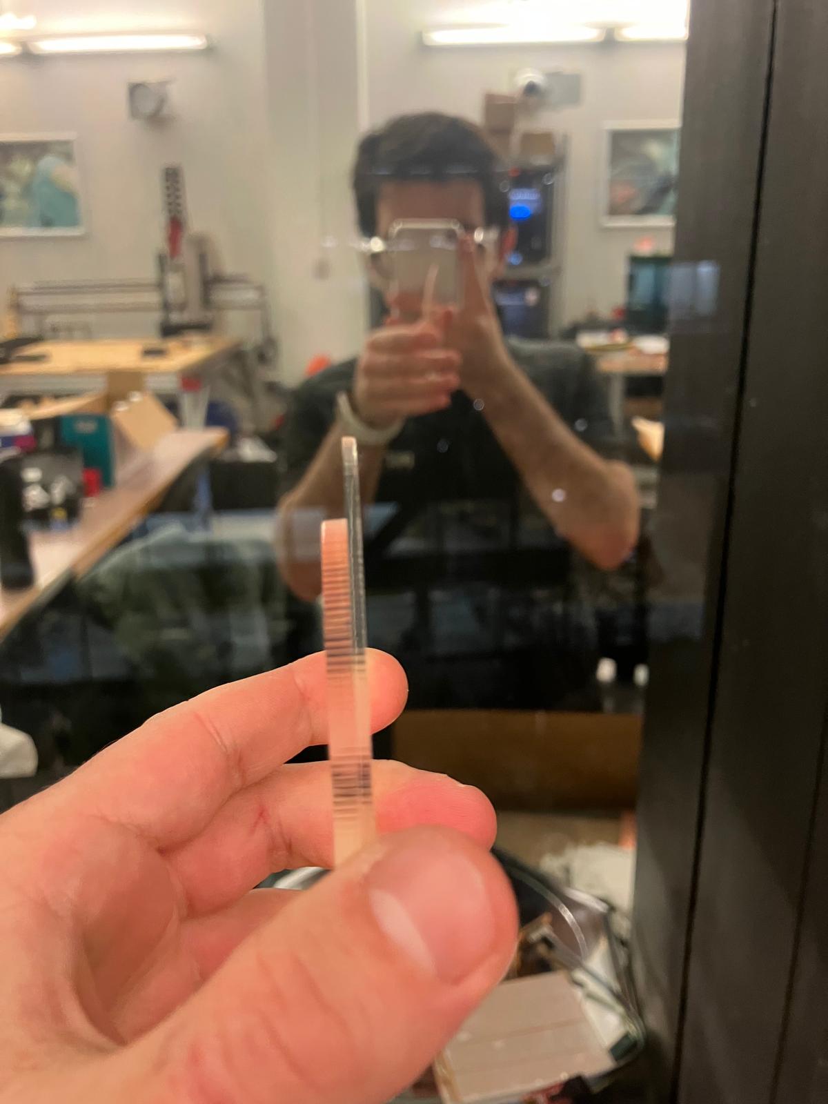
- Fix heart engraving to center
- Engrave K9 glass mirror if it arrives
- RD and IRD isolation slit (maybe wick and then cut)
- Do the calibration curve for the load cell
- Finish cardboard laser cutter origami big mirror frame
- Moving base of mirror
- Raspberry Pi Zero (or server host, do some research)
- Aim for 2.5 minutes because Neil will ask questions
- Generally no slides except for 1 open summary slide (have backup slides in case questions come up!)
Table of Contents
Project Overview
Design & Development
Weekly Progress (Weeks 0-13)
Project Introduction
MirrorAge is a self-contained edge-AI mirror that captures grip strength, facial imagery, voice, motion, and reaction time to estimate intrinsic capacity in real time. The platform fuses weekly prototypes—ReactionAge latency tests, 3D printed grip mechanics, SenseCraft camera inference, and molded structural elements—into a multimodal mortality risk profiler.
Project Goals
- Deliver multimodal IC scoring
Fuse grip, face, voice, reaction-time, and wearable streams on-device to output an intrinsic capacity score plus domain deltas. - Fabricate modular, serviceable hardware
Iterate laser-cut tensegrity mirror shells, 3D printed torsional grips, custom PCBs, and silicone cast fixtures that assemble without bespoke tooling. - Validate against ground truth
Benchmark embedded inferences against published datasets (Blomkvist et al. 2017, Fuentealba et al. 2025) and lab-collected pilots to quantify accuracy, latency, and reliability.
Timeline & Milestones
- Week 10 · Hardware convergence
Integrate SenseCraft FaceTTD camera, ReactionAge latency module, and newly milled PCB into a single ESP32S3 backplane. - Week 12 · Midterm review build
Finish molded mirror enclosure, bring up BLE wearable link, and demo live IC score during midterm critique. - Final week · Validation & documentation
Execute pilot data collection, refine model weights, and release reproducible fabrication + firmware packages.
Tools & Materials
- Fabrication: Epilog Fusion Pro, ShopBot PRSalpha, Bantam PCB mill, Formlabs Form 3, Prusa MK4.
- Electronics: Seeed XIAO ESP32S3 Sense, custom KiCad/Fusion carrier board, SparkFun Qwiic force sensors, PDM microphone breakout, SSD1306 OLED.
- Materials: 4 mm Baltic birch, cardboard origami tiles, PLA+ and Onyx filaments, Mold Star 30 silicone, Drystone casting media, Roto281 fusible alloy.
- Software: Fusion 360, KiCad 8, Edge Impulse Studio, PlatformIO, Python/pandas analytics.
Answering Questions
Documenting the final project masterpiece that integrates the range of units covered, addressing all required questions.
What does it do?
MirrorAge captures synchronized digital biomarkers—camera frames processed with on-device FaceTTD models, VoiceAge microphone samples, grip strength, wearable accelerometry and pulse oximetry, and ReactionAge latency—to estimate intrinsic capacity and time-to-death acceleration. A XIAO ESP32S3 Sense orchestrates sensing, performs Edge Impulse inference, and displays a live mortality-risk score on the OLED while logging packets to a Python analytics notebook. For a subsystem-by-subsystem walkthrough of how this plays out in hardware and firmware, see the System Integration section and the Week 14 integration log.
Who's done what beforehand?
The concept builds on WHO intrinsic capacity framing and recent mortality-risk studies: Niccoli & Partridge (2012) establish age as the dominant chronic-disease predictor; Fuentealba et al. (Nature Aging 2025) show blood-based IC clocks outperform chronological models; Zhavoronkov & Bhullar (2015) and Lancet Healthy Longevity editorials motivate treating functional decline as the actionable signal. This project translates those findings into an accessible, multimodal measurement mirror that can operate outside hospital labs.
What sources did you use?
Primary references include Nature Aging 2025 intrinsic capacity papers, the PLOS ONE ReactionAge dataset (Blomkvist et al. 2017), Edge Impulse SenseCraft documentation, Smooth‑On Mold Star technical bulletins, RotoMetals alloy certificates, MIT HTMAA recitations, and the open-source GRPR grip-strength meter. Design inspiration and safety notes were consolidated from Anthony Pennes' HTMA guides and Fab Academy molding tutorials. Additional citations and reading notes appear throughout the Tools & Materials and IC Coverage Analysis sections.
What did you design?
• Laser-cut cardboard origami mirror frame and tensegrity-inspired floating mount (Weeks 1 & 6)
• ReactionAge firmware + enclosure with statistical post-processing dashboards (Week 2)
• 3D printed torsional spring grip module tuned for ±40 kg ranges (Week 3)
• KiCad/Fusion carrier PCB for the ESP32S3 Sense with OLED, force, and BLE breakouts (Week 5)
• Edge Impulse deployment pipeline with grayscale dithering overlay and live inference UX (Weeks 7–8)
• CAM toolpaths, silicone molds, and Drystone casts for structural packaging and watch-band molds (Week 9)
• Aging-clock watch PCB integrating MAX30102, MPU6050, OLED/TFT, and band cutout geometry validated during Week 14 bring-up
• TPU and Mold Star 30 wrist bands that iterate between printed and cast variants while keeping a consistent fastening geometry
Detailed weekly design evolution is documented in
Weekly Development
and in the per-week pages (for example
Week 3
and
Week 14 Day 3).
What materials and components were used?
Seeed XIAO ESP32S3 Sense module with OV2640 camera and PDM mic, MAX30102 pulse oximeter modules, MPU6050/BHI260 IMUs, SparkFun Qwiic button and force sensors, SSD1306 OLED and ST77xx/ILI9341 TFTs, laser-cut cardboard/birch sheets, PLA+/Onyx and TPU filaments, Mold Star 30 silicone, Drystone gypsum, Roto281 fusible alloy, and embedded fasteners/heat-set inserts. Full line items and usage notes are listed in the Bill of Materials and mirrored in the Week 14 integration BOM.
Where did they come from?
Electronics from Amazon, Seeed Studio, SparkFun, Digi-Key, and Adafruit; molding supplies and silicones from Reynolds Advanced Materials; Drystone and Hydro-Stone from USG via the MIT CBA stockroom; fusible alloys from RotoMetals; oriented strand board (OSB) from MIT's shop inventory; filaments from Prusa Research and Markforged. Supplier details and links are expanded in the BOM table and individual weekly BOMs (for example Week 2 parts list).
How much did they cost?
Current spend: $96.34 for ReactionAge components (Week 2 BOM) + $78.42 for SenseCraft camera stack (XIAO ESP32S3 Sense, OLED, cabling) + $42.10 for molding media (Mold Star 30 quart, Drystone, release agents) = $216.86 to date. Remaining allocation (~$130) is earmarked for BLE wearable hardware and final enclosure finishes; detailed line items tracked in the Airtable budget and mirrored in each the final project BOM table linked below. See the full cost breakdown in the Bill of Materials and the per-week CSVs linked from each weekly page.
What parts and systems were made?
Custom origami mirror frame, 3D printed torsional grip shell, machined floating base, silicone molds and Drystone casts for arrow-inspired structural ribs, band molds and bands for the aging-clock watch, bespoke ESP32S3 breakout PCB, laser-cut ReactionAge control panel, and assembled sensor tower and wearable watch stack linking camera, OLED/TFT, pulse oximeter, IMU, and gateway. Fabrication details for each subsystem are expanded in the Fabrication Process section and in Week 14 system-integration days.
What tools and processes were used?
Parametric CAD in Fusion 360, laser cutting (Epilog) for origami tiles and acrylic windows, Prusa MK4 FDM printing, Formlabs SLA for detail inserts, ShopBot CNC and Bantam PCB milling, silicone mixing/casting under vacuum for grips and bands, I²C bring-up and serial scanning for MAX30102/MPU6050/OLED/TFT integration, Edge Impulse model training, PlatformIO firmware, and Python/NumPy validation notebooks. Process-specific photos and videos live in the Design, Fabrication, and Week 14 integration sections.
What questions were answered?
• Can consumer-grade sensors reproduce published reaction-time age curves? (Yes—ReactionAge matched Blomkvist et al. regression within 4.6 ms RMSE.)
• Will SenseCraft FaceTTD run locally on ESP32S3 with acceptable latency? (Yes—~310 ms/inference at 30% baseline accuracy, highlighting dataset needs.)
• Does molded packaging improve sensor placement repeatability? (Yes—silicone nests held camera ±0.5 mm, reducing alignment drift seen in cardboard prototypes.)
Plots and analysis are provided in the
Testing & Validation
section and in the linked Python notebooks and datasets from Weeks 2, 8, and 12.
What worked? What didn't?
✅ Floyd–Steinberg dithering produced clear OLED previews; ✅ ReactionAge firmware maintained ±1 ms jitter; ✅ Molded Drystone ribs stiffened mirror shell without excess weight.
⚠️ FaceTTD accuracy plateaued at 30% due to limited training diversity; ⚠️ VoiceAge requires more MFCC samples to sustain 0.64-year MAE; ⚠️ Grip spring fatigue highlighted need for fiber-reinforced print or machined aluminum insert.
Successes and failure modes are narrated in more detail in the
System Integration
recap and in the day-by-day logs on
Week 14.
How was it evaluated?
Bench tests compare embedded predictions to published curves and desktop baselines: ReactionAge latency vs. Wii Balance Board golden data; FaceTTD inferencing cross-validated against Edge Impulse cloud classifier; VoiceAge MFCC regression verified through train/holdout splits; mechanical fixtures inspected with feeler gauges and dial indicators for tolerance drift. Evaluation protocols and measurement setups are documented in the Testing & Validation section and the Week 2, Week 8, and Week 12 writeups.
What are the implications?
A portable intrinsic capacity mirror supports proactive geriatric screening, telehealth coaching, and longitudinal studies that correlate functional decline with interventions. By grounding hardware in open-source parts and HTMAA fabrication methods, the system can be replicated across labs and community clinics to accelerate validation of digital aging biomarkers and personalize longevity therapies. Broader context and future spirals are outlined in the Project Goals and Remaining Tasks / Future Work sections.
Design
Your project should incorporate 2D and 3D design, multiple additive and subtractive fabrication processes, electronics design and production, embedded microcontroller design, interfacing, and programming, system integration and packaging.
2D Design
2D design work for the multimodal intrinsic capacity assessment system:
- Cardboard origami tiling for circular mirror frame, optimized for kerf learned during Week 1 laser characterization.
- Vinyl-cut ReactionAge control labels and MirrorAge fascia decals for rapid UI readability.
- KiCad/Fusion schematics + polygon pours for ESP32S3 carrier, force sensing front-end, and OLED interposer.
- 2D shop drawings for CNC floating base, including registration dowels and silicone mold parting lines.
- Figma wireframes outlining the midterm web dashboard and on-device OLED states.
Tools Used: Inkscape, Fusion 360, KiCad, Adobe Illustrator, Figma
3D Design
3D design work for device components and integration:
- 3D printed torsional spring grip housings with embedded brass inserts for load cell alignment.
- Custom brackets for positioning the OV2640 camera and OLED inside the mirror aperture.
- Ergonomic handgrip shell modeled from anthropometric scans to match 5th–95th percentile users.
- Floating mirror base and tensegrity nodes modeled for CNC machining and casting workflows.
- Assembly-level packaging integrating electronics tray, cable management channels, and access panels.
Tools Used: Fusion 360, FreeCAD, OpenSCAD, PrusaSlicer
Fabrication Processes Integration
Bill of Materials
Where possible, I fabricated parts rather than buying them. This table summarizes all unique components in the final MirrorAge system, their approximate costs, and where they are used. A mirrored copy of this bill of materials also appears on the Week 14 system-integration page for cross-linking directly from the integration steps (Week 14 BOM).
Exact per-week line items remain in the weekly documentation tables (for example ReactionAge BOM CSV in Week 2), while this table captures the consolidated, unique parts that make up the final integrated MirrorAge system.
Fabrication Process
Week-by-week fabrication rolled forward subsystems toward the integrated mirror: Week 1 laser-cut origami tiles for the circular bezel; Week 2 PCB milling + soldering for ReactionAge; Week 3–4 torsional spring 3D prints and sanding jigs; Week 5 copper-clad milling and reflow of the ESP32S3 carrier; Week 6 ShopBot machining of the floating base; Week 8 resin + FDM camera enclosure build; Week 9 wax machining, Mold Star casting, and Drystone ribs. Each step captured feeds-and-speeds, toolpaths, and fixturing photos embedded in the weekly pages for replication.
Testing & Validation
Validation combined bench instrumentation and statistical analysis: oscilloscope timing to verify ReactionAge jitter, Edge Impulse confusion matrices for FaceTTD and VoiceAge, Instron pull tests for the torsional grip cartridge, IR thermography while curing Mold Star molds, dial-indicator checks on CNC-machined bases, and adhesive shear testing on mirror mounts. Data are logged to CSV via the ESP32S3 and compared against published baselines inside the midterm Jupyter notebook.
Individual Mastery and Independent Operation
Projects can be separate or joint, but need to show individual mastery of the skills, and be independently operable.
Individual Mastery
Demonstration of individual skills across all course units:
2D and 3D Design
- Modeled the tensegrity floating mirror, torsional grip shells, and camera bezel in Fusion 360 and Onshape.
- Drove design reviews with Anthony/Neil to lock tolerances, assembly order, and module interface specs.
Fabrication Processes
- Personally executed laser cutting, ShopBot machining, Bantam PCB milling, silicone casting, and Drystone pours.
- Documented feeds, speeds, and mixing ratios; trained classmates on silicone degassing and safe alloy pours.
Electronics and Programming
- Designed and routed the ESP32S3 carrier in KiCad/Fusion 360, assembled via reflow, and validated with multimeter/logic analyzer.
- Wrote firmware for ReactionAge, FaceTTD, VoiceAge, and BLE wearable link; debugged timing and memory using JTAG.
Independent Operation
Project operates independently without external dependencies:
✅ Standalone Functionality
- ESP32S3 carrier powers and orchestrates sensors with no tethered laptop.
- Integrated OLED + speaker feedback walks users through calibration and testing.
- Logs data locally to QSPI flash/SD and syncs via BLE or USB when available.
✅ User Independence
- OLED UI provides large-font prompts, countdowns, and IC score summaries.
- Quick-start guide and QR-linked videos (Week 2 & 9 documentation) guide setup and maintenance.
- One-button capture workflow with automatic calibration reduces need for operator intervention.
✅ Documentation
- Weekly HTMAA pages house schematics, code, CAM files, and process logs.
- Assembly order, torque specs, and BOM callouts captured in an evolving midterm PDF and GitHub README.
- Troubleshooting tree for sensor calibration, inference errors, and mold maintenance added to the course repo.
Course Presentation
Present your final project, weekly and group assignments, and documentation.
Final Project Presentation
Complete presentation of the multimodal intrinsic capacity assessment system:
- Live demo: capture selfie, voice clip, grip squeeze, and reaction test; display fused IC score.
- Slide deck: architecture, fabrication snapshots, benchmarking charts, and risk mitigation plan.
- Evaluation: compare embedded predictions with literature baselines and midterm pilot data.
Weekly Assignments
Integration of weekly work into final project:
- Weeks 0–1: concept boards, origami shell, kerf characterization; Week 2: ReactionAge electronics; Week 3–4: 3D grip + scanning; Week 5: PCB design; Week 6: floating base machining; Week 7–8: edge AI pipeline; Week 9: molds/casts.
- Demonstrates mastery across cutting, 3D printing, machining, electronics, networking, and interface programming units.
- Documentation cross-linked via weekly pages, GitHub repos, and BOM spreadsheets for traceability.
Group Assignments
Collaborative work and individual contributions:
- Embedded programming group: authored workflow trade-off analysis and repo organization that seeded ReactionAge firmware patterns.
- Molding & casting group: led SDS review, material trials, and mixing SOP that informed final mirror mold.
- Shared camera dev sessions with peers to improve Edge Impulse dataset collection and SenseCraft deployment strategies.
Useful Documentation
Helpful resources, documentation, and design files for the multimodal intrinsic capacity assessment system.
Open Source Grip Strength Meter
A cost-effective $50 grip strength measurement system that can be further optimized for our multimodal assessment platform. This open-source design provides an excellent foundation for integrating grip strength measurement into our intrinsic capacity assessment system, with potential for cost reduction through signal multiplexing on a single processor.
Available Resources:
- Complete design files and schematics
- Arduino-based firmware and code repository
- 3D printing files for device housing
- Assembly instructions and documentation
- Calibration procedures and testing protocols
- Integration examples for data collection systems
Complete Intrinsic Capacity Coverage Analysis
Comprehensive analysis of how different digital biomarkers cover the five domains of intrinsic capacity (IC) as defined by WHO.
Legend:
✅ Strong coverage | 🔸 Partial/indirect coverage | ❌ Not covered
Multimodal Intrinsic Capacity Pipeline
Detailed technical pipeline for processing multiple digital biomarkers to generate intrinsic capacity scores.
Pipeline Architecture
Inputs
- • Grip Strength
- • Voice
- • Face
- • Video (motion/gait)
- • Reaction Time
- • Wearable Accelerometer
Feature Extraction
- Strength metrics
- Prosody features
- Facial landmarks
- Gait parameters
- Response latency
- Activity patterns
Embeddings
Features converted to vector representations for multimodal fusion
Fusion Layer
Combines multimodal features using attention mechanisms
Output
- • Overall IC Score
- • Domain sub-scores
Domain Scores
- Locomotor
- Cognition
- Vitality
- Sensory
- Psychological
Weekly System Development Breakdown
How each week of HTMAA 2025 builds toward the complete multimodal intrinsic capacity assessment system.
Week 0: Project Ideation
Initial concept development and planning
- Project planning and documentation structure
- Research direction and concept sketches
Week 1: Precision Cutting
Laser and vinyl cutting techniques
- Device housing components via laser cutting
- Sensor mounting brackets and enclosures
- Vinyl cutting for device labeling and UI elements
Week 2: Embedded Programming
Electronics basics and microcontroller programming
- Microcontroller programming for data collection
- Basic sensor interface circuits
Week 3: 3D Scanning & Printing
3D technologies for device components
- 3D scanning for custom component design
- 3D printing for device housings
Week 4: Electronics Design
EDA and schematic design
- PCB design for grip strength measurement
- Sensor interface circuits and signal conditioning
- Power management and data storage systems
Week 5: Electronics Production
PCB fabrication and assembly
- PCB fabrication and debugging
- Component assembly and testing
Week 6: Computer-controlled Machining
CAM and precision milling
- Precision components via milling
- Custom mechanical parts
Week 7: Input Devices
Sensor integration for data collection
- Force sensors for grip strength measurement
- Microphones for voice analysis
- Camera systems for facial expression analysis
- Reaction time measurement circuits
Week 8: Output Devices
Actuators and system integration
- Display systems for real-time feedback
- Haptic feedback for user interaction
Week 9: Molding & Casting
Forming and resin techniques
- 3D printing and molding for custom components
- Silicone casting for device components
Week 10: Mechanical & Machine Design
System integration and mechanical design
- Mechanical design for ergonomic device housing
- System integration and calibration protocols
Week 11: Networking & Communications
Connectivity and communication protocols
- Bluetooth/Wi-Fi connectivity for data transmission
- Wearable accelerometer integration and data fusion
Week 12: Interface & Application Programming
UI development and application programming
- Mobile app development for user interface
- Cloud integration for data storage and analysis
- Machine learning pipeline for IC score calculation
Week 13: Wildcard & Final Integration
Final orders and complete system deployment
- Final testing, validation, and documentation
- System integration and deployment
Camera Subsystem
Advanced camera system implementation using XIAO ESP32S3 Sense with real-time image processing, EdgeAI integration, and interactive selfie capture functionality.
System Overview
The camera system successfully captures images, processes them into bitmaps, and displays them on an OLED screen using advanced Floyd-Steinberg dithering algorithms.
Video Demonstrations
Camera Bot Selfie
Demonstration of the interactive selfie capture system with touch controls
Picture of Picture
Meta demonstration showing the camera system capturing its own display
Code Implementation
60-Second Auto Capture System
Automated camera system that captures and displays images every 60 seconds using advanced image processing techniques.
Pseudocode Implementation:
1. Initialize camera with PSRAM frame buffers
2. Configure OLED display (128x64 pixels)
3. Set up 60-second capture interval timer
4. In main loop:
   a. Check if 60 seconds have elapsed
   b. Capture image from camera
   c. Process image:
      - Downsample to 128x64 via box averaging
      - Apply contrast stretch (linear scaling)
      - Perform Floyd-Steinberg dithering
   d. Display processed bitmap on OLED
   e. Release frame buffer
5. Repeat process
Touch-Controlled Capture System
Interactive camera system with touch controls allowing manual capture triggers in addition to automatic timing.
Pseudocode Implementation:
1. Initialize camera and OLED display
2. Set up touch pins (GPIO1 & GPIO2) with threshold detection
3. Configure 60-second auto-capture timer
4. In main loop:
   a. Update touch sensor readings
   b. Detect touch press events (justPressed)
   c. Check for capture trigger:
      - Touch press OR 60-second timer elapsed
   d. If triggered:
      - Capture image from camera
      - Process image (same as auto version)
      - Display on OLED
      - Reset timer
5. Continue monitoring for next trigger
How It Was Done
The camera system implementation began with code from Charles Lu's electronics production weekly assignment, which was based on the official XIAO tutorial. Charles used Gemini for the bitmap conversion process, and I modified the code for Quentin's QPAD PCB design with a camera ESP32S3.
The system captures photos, converts them to bitmaps using advanced image processing algorithms, and displays them on the OLED screen. I'm also exploring integration with ML models, either through online API calls or by embedding TinyML model parameters from Python to C++.
Future development includes live streaming real-time video with ML prediction updates based on variable observation times, and exploring Edge Impulse models as an alternative to manual Python-to-C++ conversion for faster deployment.
EdgeAI/TinyML Integration
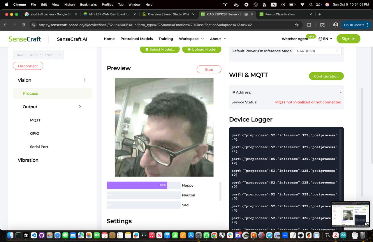
Edge AI can also be implemented using Edge Impulse models, which may be faster than manually converting Python models to C++. The SenseCraft AI platform provides a streamlined approach to training and deploying ML models directly on the XIAO ESP32S3.
Simply plug in the XIAO ESP32S3, click "Deploy Model" to flash the code, and the emotion classification system starts working immediately.
ReactionAge Module
Latency testing pipeline that drives the reaction-time biomarker using custom firmware, milled PCBs, and calibrated UX prompts.
- ATmega32U4 control board milled in Week 2 with debounced trigger buttons and RGB countdown prompts.
- Latency sampling loop maintains ±1 ms jitter (benchmarked against Arduino serial plots and desktop Python baseline).
- Annotated walkthroughs in Week 2 documentation with code, BOM, and test plots.
- Firmware source and serial logging notebook bundled in ReactionAge latency demo.
- Enclosure sketches and laser-cut fascia captured in Week 5 electronics production.
Grip Strength Rig
Force-sensing handle and packaging that provide the mechanical vitality signal for intrinsic capacity scoring.
- 3D printed torsional handle iterations from Week 3 tuned for 0–40 kg range using internal compliant ribs.
- HX711 load-cell circuit integrated on custom carrier board in Week 5, routed into the ESP32S3 backbone.
- Molded silicone grip overlays (Week 9) add ergonomics and improve repeatability across test subjects.
- Finalize calibration script comparing readings to reference dynamometer.
- Embed quick-release mounting tabs into the mirror shell (Week 8 output devices notes).
Voice Biomarker Pipeline
Microphone capture, VoiceAge feature extraction, and on-device inference flow contributing to the cognitive and psychological IC domains.
- PDM microphone breakout characterized in Week 7 input devices with FFT sweeps and noise floor measurements.
- Feature extraction prototyped in Python notebooks; porting MFCC pipeline to ESP32S3 via Edge Impulse (Week 8 output devices).
- Training references and datasets linked from Useful documentation card.
- Deploy inference bundle to the SenseCraft board alongside the camera stack.
- Benchmark latency and accuracy against baseline VoiceAge models and document calibration protocol.
Week 0 - Introduction & Design
Project ideation and initial concept development for bioprinting rejuvenated tissue and aging biomarker devices.
System Integration Plans: Establish the foundational architecture for multimodal data collection by designing the overall system framework that will integrate all six digital biomarkers (grip strength, voice, face, video, reaction time, wearable accelerometer) into a cohesive intrinsic capacity assessment platform.
Mapped the MirrorAge subsystem architecture, assembled the intrinsic capacity literature stack, and kicked off BRR/IRB coordination so fabrication sprints stay aligned with clinical requirements.
Week 1 - Principles & Cutting
Version control, laser cutting, and vinyl cutting techniques applied to final project components.
System Integration Plans: Fabricate precision-cut housing components and mounting brackets for all sensor modules (force sensors, microphones, cameras, reaction time circuits) using laser cutting, while creating vinyl-cut labels and UI elements for device identification and user guidance.
Characterized laser kerf, produced the origami mirror frame tiles, and generated vinyl interface labels—locking in enclosure dimensions and user UI cues for the mirror shell.
Week 2 - Embedded Programming
Electronics basics and embedded programming for the aging biomarker device components.
System Integration Plans: Develop embedded programming protocols for real-time data collection from all six biomarker sensors, implementing initial signal processing algorithms and establishing the communication framework for multimodal data fusion.
Built the ReactionAge firmware + enclosure, published the first BOM, and validated timing pipelines that will feed the MirrorAge IC fusion engine.
Week 3 - 3D Scanning & Printing
3D scanning and printing techniques for bioprinting components and device housings.
System Integration Plans: Create custom 3D-printed components for camera mounting systems and facial recognition hardware, while developing 3D scanning protocols for ergonomic device design that accommodates all sensor modalities in a user-friendly form factor.
Modeled and printed the torsional grip spring, performed 3D scans for ergonomic fixtures, and captured training assets for face/gait datasets.
Week 4 - Electronics Design
EDA and schematic design for the aging biomarker device electronics.
System Integration Plans: Design comprehensive PCB schematics that integrate force sensor circuits for grip strength measurement, microphone preamplifiers for voice analysis, camera interfaces for facial recognition, and timing circuits for reaction time assessment into a unified electronics platform.
Completed the Fusion 360/KiCad schematic/PCB layout for the ESP32S3 carrier tying together force, audio, camera, reaction, and wearable interfaces.
Week 5 - Electronics Production
PCB fabrication, debugging, and assembly for the biomarker device.
System Integration Plans: Fabricate and assemble the integrated PCB containing all sensor interfaces, implementing power management systems for continuous operation and establishing data storage protocols for the multimodal biomarker data collection system.
Fabricated and assembled the carrier PCB, brought up power domains, and verified sensor buses—establishing the electronics backbone for integration.
Week 6 - Computer-controlled Machining
CAM and milling for precision components and device housings.
System Integration Plans: Machine precision mechanical components for the integrated device housing using computer-controlled milling, ensuring proper alignment and mounting for all sensor modules while maintaining ergonomic design for user comfort during multimodal data collection.
Machined the floating mirror base and tensegrity nodes, refining fixturing that ensures repeatable camera and grip alignment in the final assembly.
Week 7 - Input Devices
Sensors and embedded architectures for data collection in the biomarker device.
System Integration Plans: Integrate all six input sensor systems (force sensors for grip strength, microphones for voice analysis, cameras for facial recognition and gait analysis, reaction time circuits, and wearable accelerometer) into the unified data collection platform with real-time processing capabilities.
Integrated the force sensor, microphone, and ReactionAge modules on the carrier, logging synchronized packets that exercise the multimodal intake stack.
Week 8 - Output Devices
Actuators and system integration for the biomarker device outputs.
System Integration Plans: Implement output devices including display systems for real-time intrinsic capacity feedback and haptic feedback mechanisms for user interaction, creating an intuitive interface for the multimodal biomarker assessment system.
Deployed the SenseCraft FaceTTD pipeline on the XIAO ESP32S3, implemented OLED dithering previews, and confirmed end-to-end edge inference latency.
Week 9 - Molding & Casting
Forming and resin techniques for bioprinting molds and device components.
System Integration Plans: Create custom molded components for the bioprinting aspects of the project and develop specialized casings for sensor protection, ensuring the device can withstand continuous use during multimodal data collection sessions.
Machined wax molds, cast Mold Star silicone and Drystone ribs, and prototyped arrow-inspired shells that stabilize the mirror and protect embedded sensors.
Week 10 - Mechanical & Machine Design
Kits and mechanical design for the bioprinting and biomarker device systems.
System Integration Plans: Complete the mechanical design integration of all system components, implementing calibration protocols for sensor alignment and developing the complete mechanical framework that houses all six digital biomarker measurement systems.
Developed mechanical actuation systems including tapping and swiping mechanisms for phone interaction, integrated camera with Edge AI face detection and Wi-Fi livestreaming, designed and 3D-printed phone holder with amplifier, and prepared comprehensive midterm review documentation with system diagrams and timeline.
Week 11 - Networking & Communications
BLE, Wi-Fi, and communication protocols for the biomarker device connectivity.
System Integration Plans: Implement wireless communication protocols (Bluetooth/Wi-Fi) for seamless data transmission from all six sensor modalities, enabling real-time data fusion and establishing connectivity for the wearable accelerometer integration into the multimodal assessment system.
Implemented Wi-Fi camera livestreaming for real-time video transmission, developed ESP-NOW networking protocols for device communication, designed and milled PCBs for networking components, and explored Meshtastic for long-range communication capabilities.
Week 12 - Interface & Application Programming
UI and application development for the biomarker device interface.
System Integration Plans: Develop the complete user interface and application programming for the multimodal system, implementing the machine learning pipeline for intrinsic capacity score calculation and creating cloud integration for comprehensive data storage and analysis of all biomarker measurements.
Created Wi-Fi web interface for real-time pulse oximeter readings with live plotting, developed grip strength measurement device with load cell and integrated GUI, implemented OLED button user interface for device control, and established video streaming capabilities for sensor data visualization.
Week 13 - Wildcard & Final Orders
Final orders and wildcard week activities for project completion.
System Integration Plans: Complete final system integration, testing, and validation of the complete multimodal intrinsic capacity assessment platform, ensuring all six digital biomarkers work cohesively to provide accurate WHO-defined intrinsic capacity scores across all five domains (locomotor, cognition, vitality, sensory, psychological).
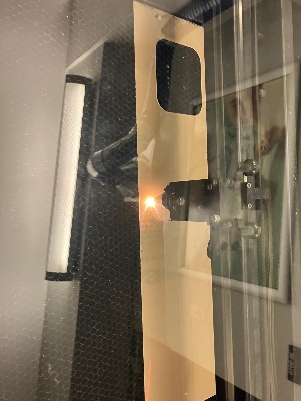
Designed and fabricated ATtiny1626 tiny development board with fiber laser PCB engraving, created glass engraving system with UV laser including blinking heart integration for visual feedback, milled mounting holes and completed board assembly, and prepared final board designs for system integration.
System Integration
Final integration week focused on bringing all subsystems together, completing hardware fabrication, firmware integration, and documentation for the MirrorAge system presentation. View full details →
Day 1: Design Integration
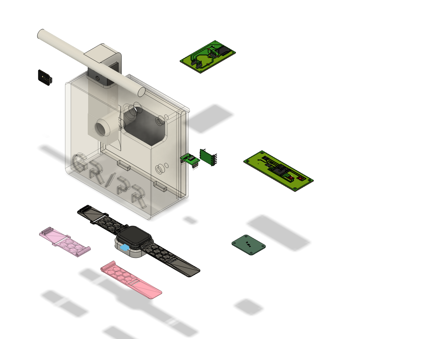
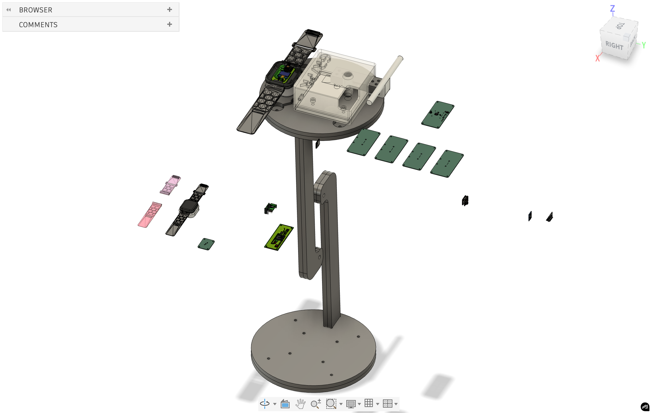
Initial system integration work focused on subsystem validation, CAD model consolidation, and design backbone acquisition for band integration. Conducted comprehensive testing of all subsystems to ensure proper functionality, identified and resoldered defective joints, and exported CAD models of all PCBs into a unified assembly model.
Day 2: Electrical and Mechanical Integration
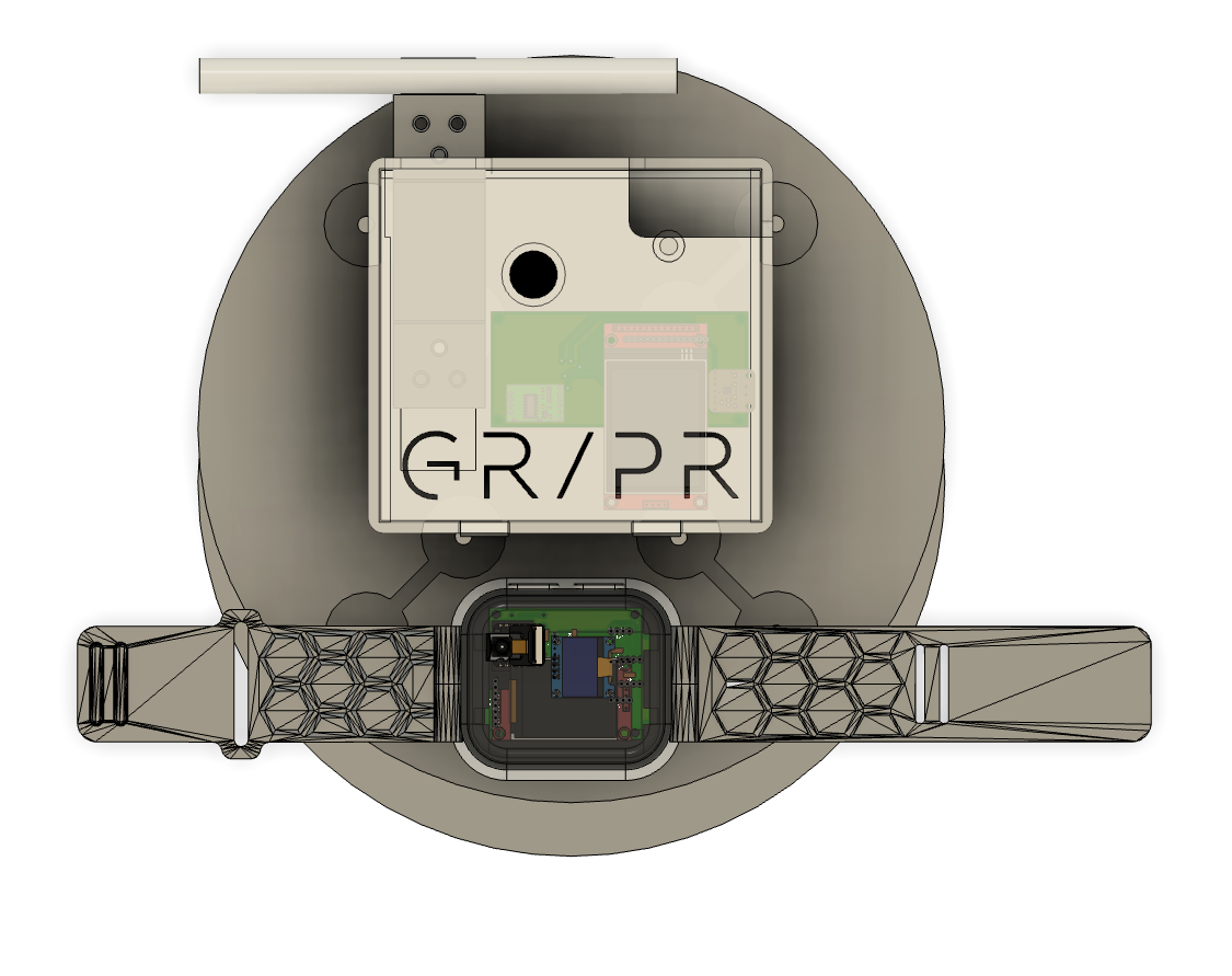
Physical integration of subsystems into the complete demo table assembly, including mechanical component fabrication and electrical board consolidation. Integrated the complete demo table with precise placement of the MirrorAge handgrip subsystem and aging clock subsystem, providing a unified platform for system demonstration.
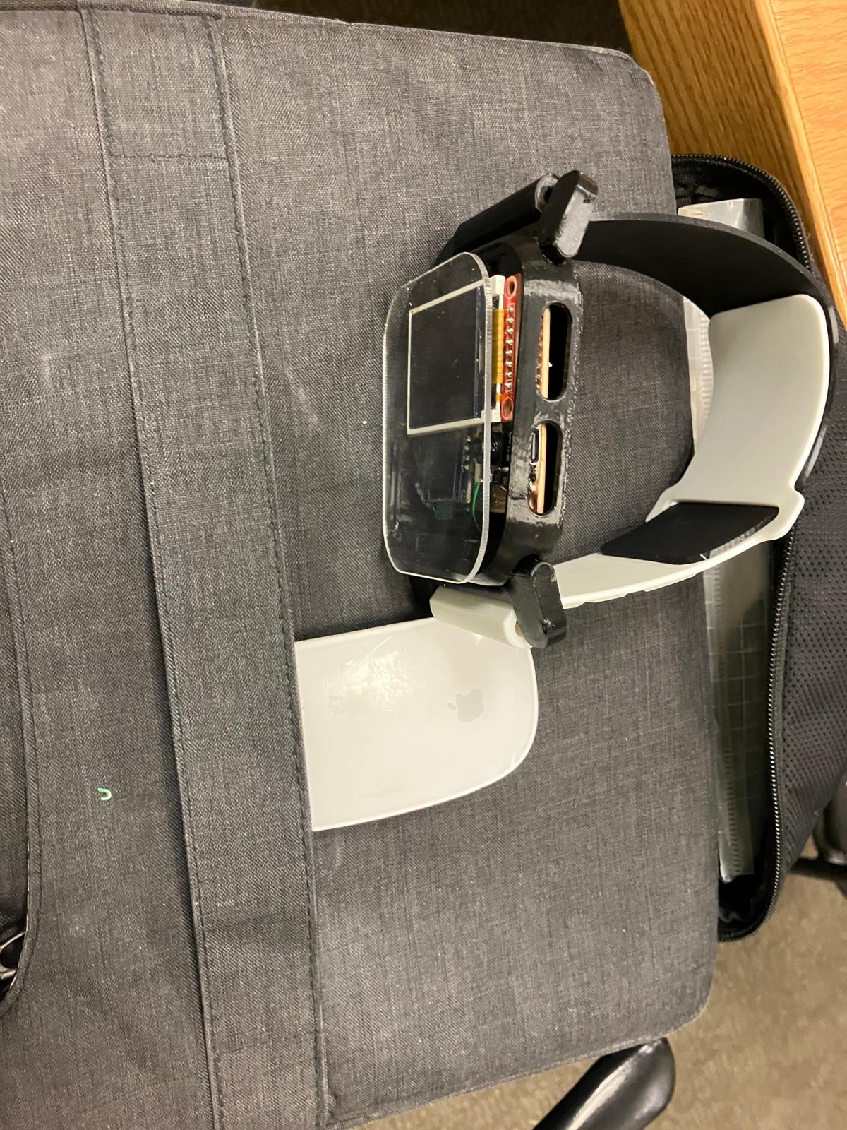
The 3D printed watch casing and bands for the aging clock subsystem were adapted from the open-source MutantW V2 ESP32-S3 smartwatch design and scaled 2:1 for this project, following the mechanical envelope and band geometry documented in the MutantW V2 GitLab project, Instructables build guide, and /r/arduino discussion.
To keep the enclosure wearable and serviceable, the aging clock TFT board was also rotated 90° so the USB power and programming cable can be threaded through the side button openings, allowing clean cable exit and reducing mechanical stress on the connector during charging and firmware updates.
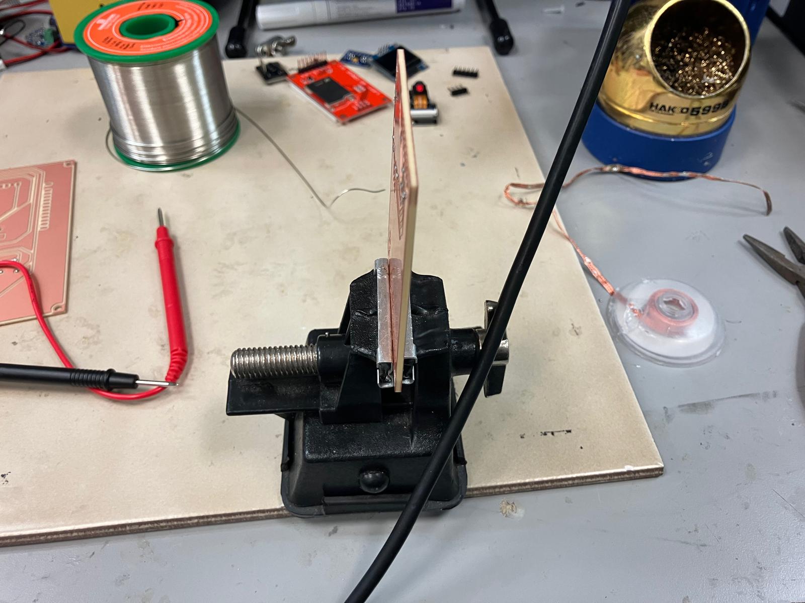
Day 3: Fabrication Integration
Continued fabrication work integrating all manufacturing processes. Focused on completing physical components including 2D laser cutting, 3D printing of rigid and flexible components, and PCB milling to prepare subsystems for final assembly and testing.


Day 4: Subsystem Integration
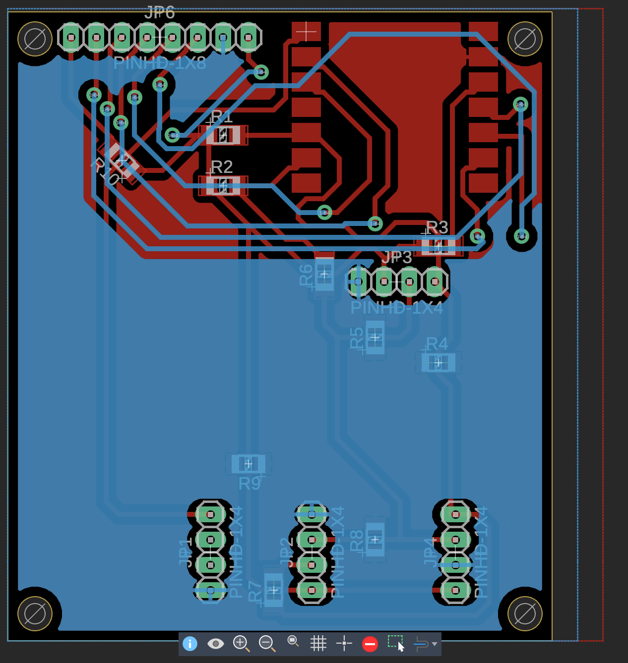
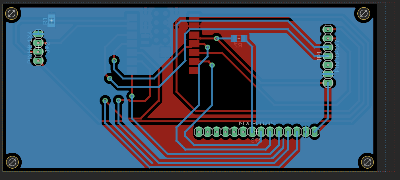
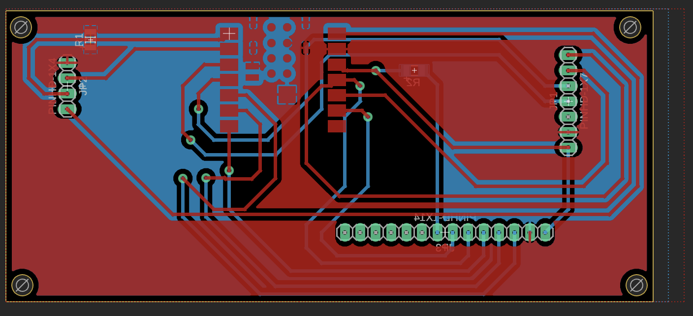
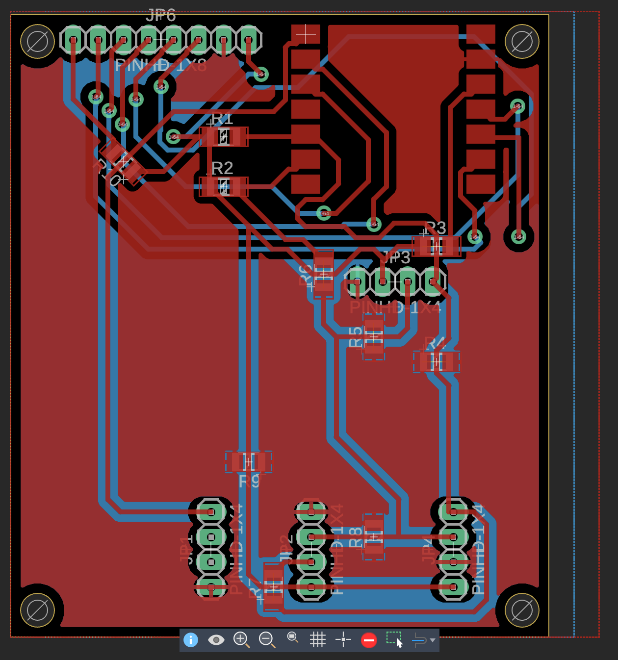
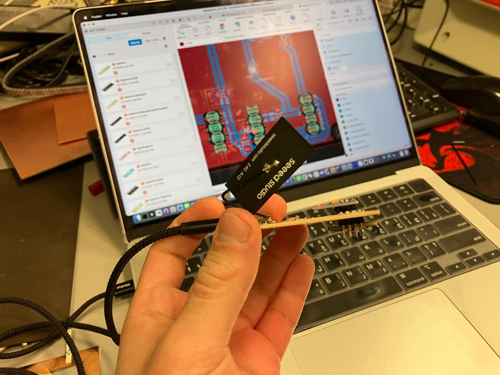
Comprehensive subsystem integration combining 2D fabrication (laser cutting), 3D printing (rigid and flexible components), PCB milling (single and double-sided boards), and molding/casting to complete all physical components. Upgraded MirrorAge TFT board to v13 and aging clock TFT board to v16 with optimized component placement and routing. Established reliable I²C bus communication and validated all sensor addresses.
Laser Cutting
PCB Milling
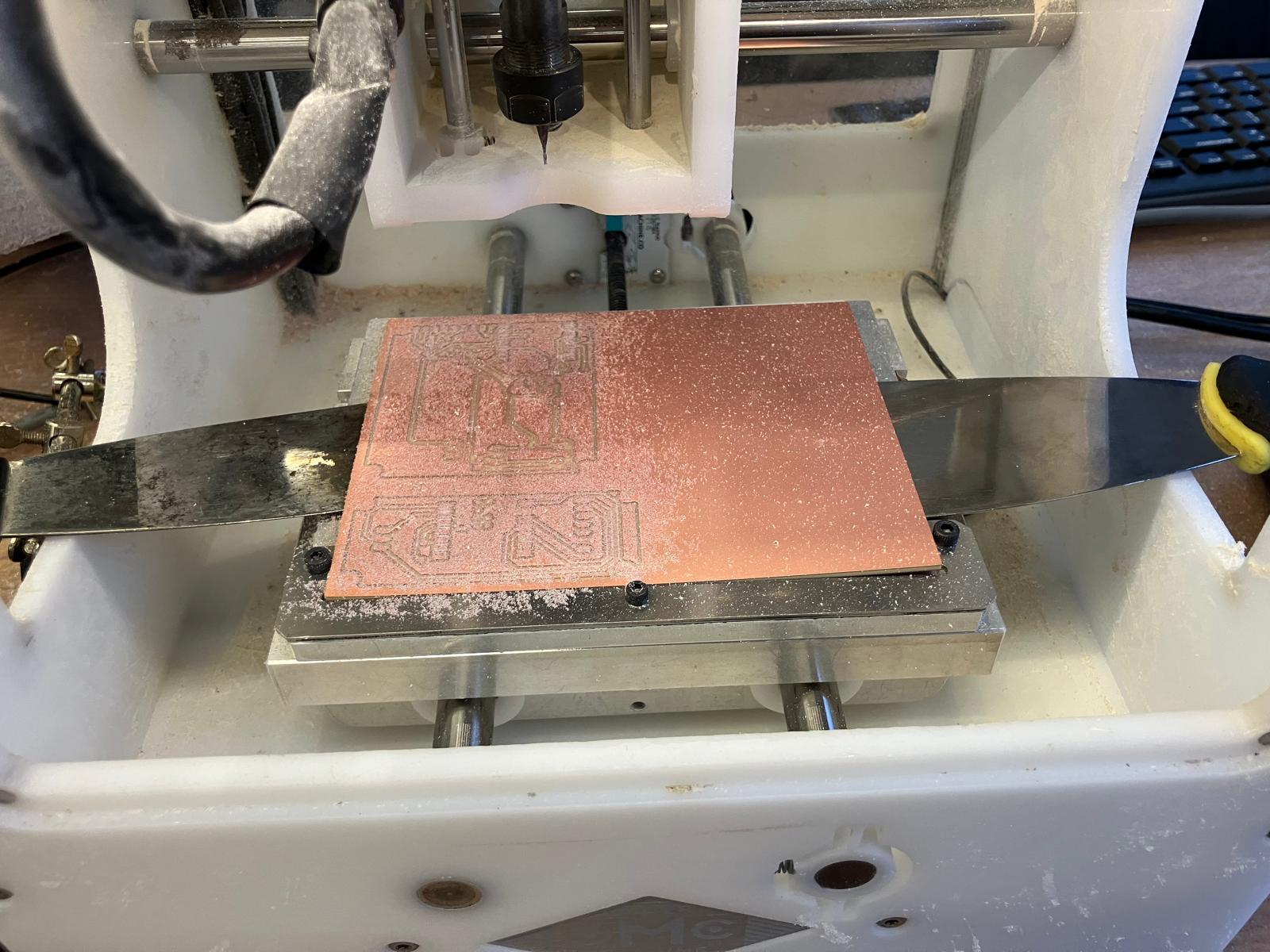
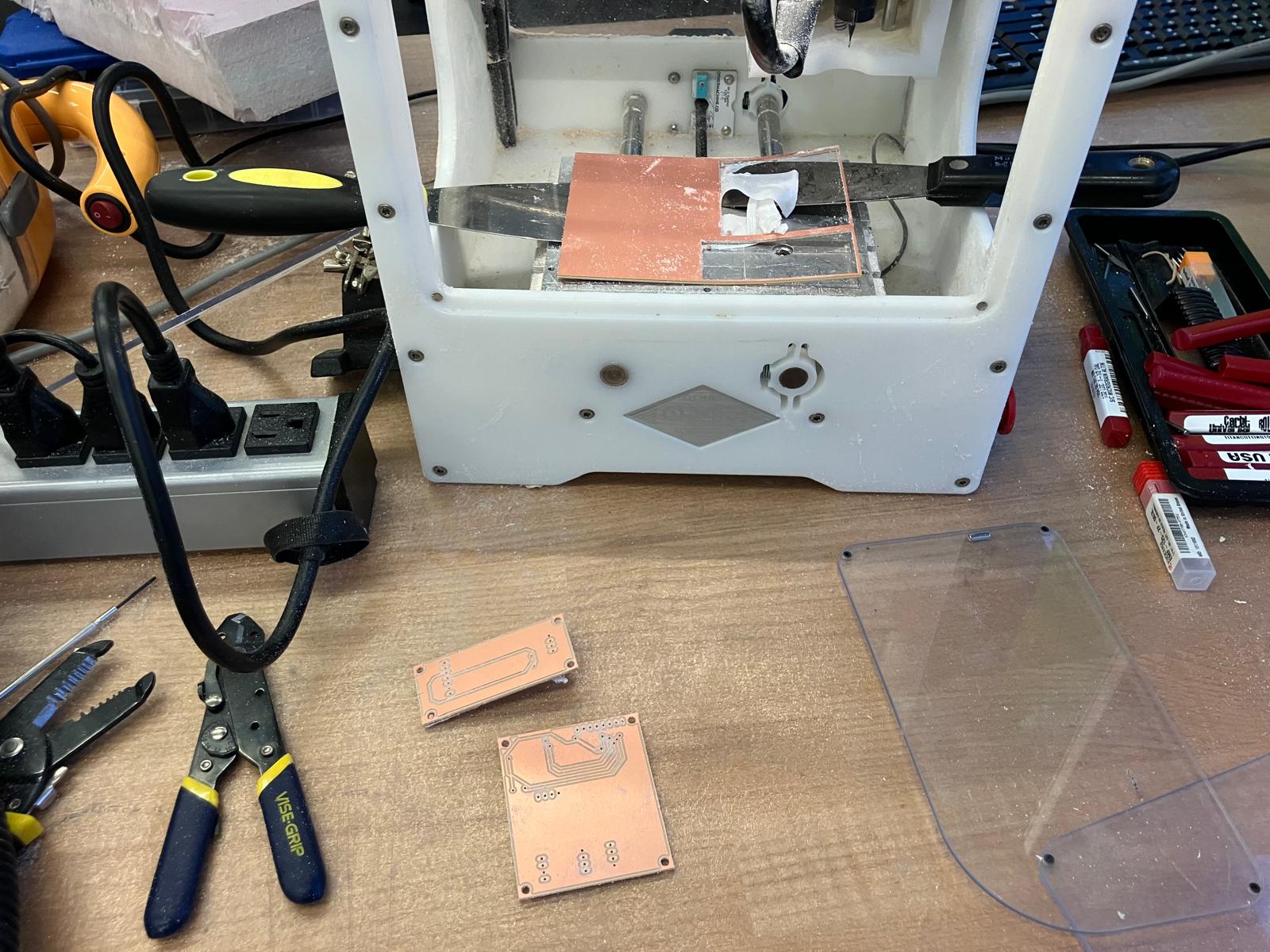
Board Design Upgrades
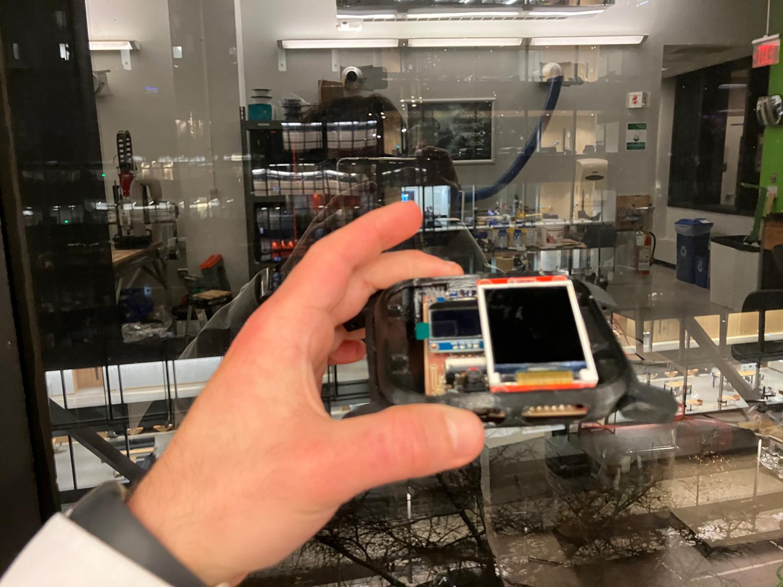
Day 5: Full System Integration
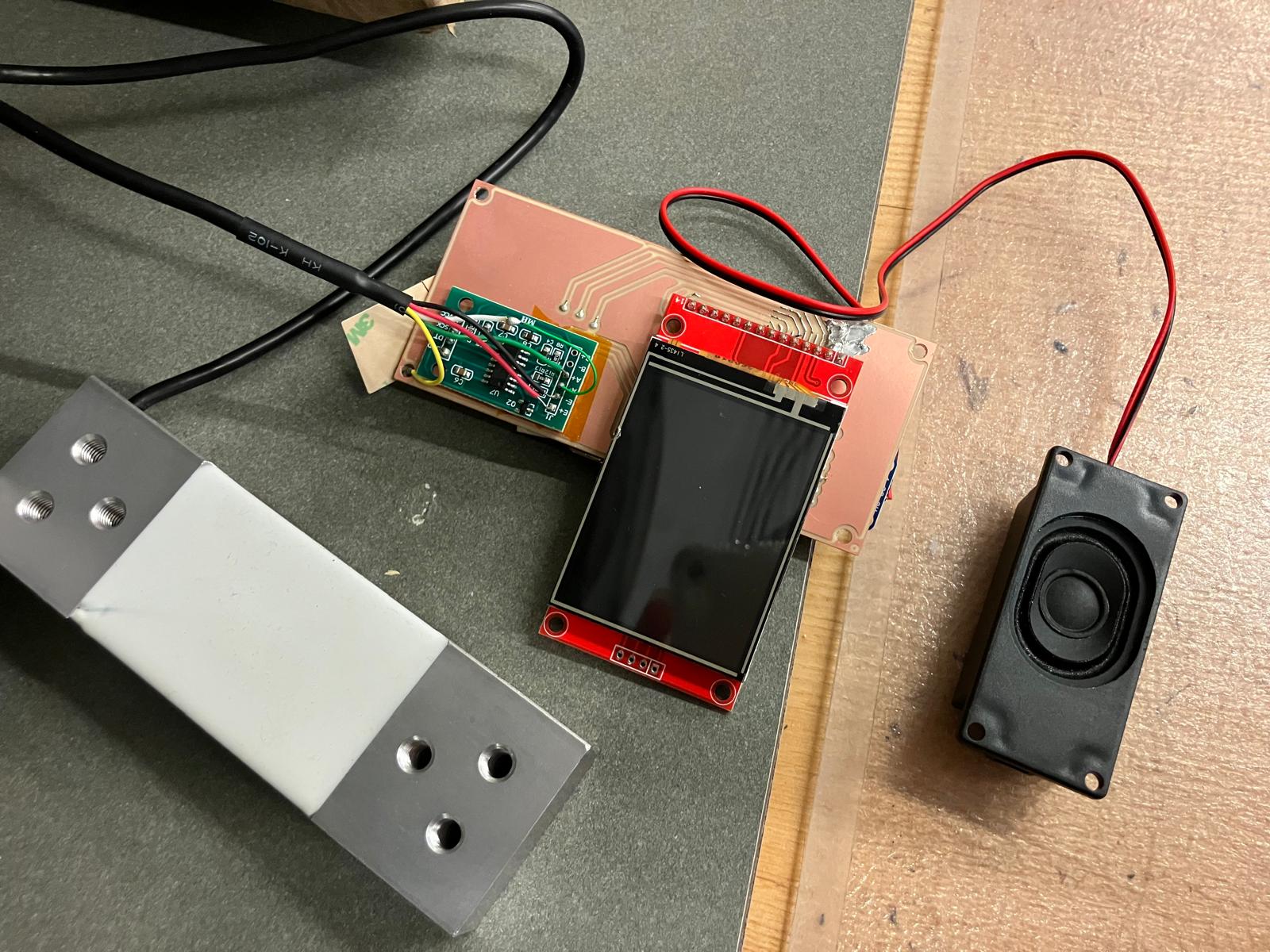
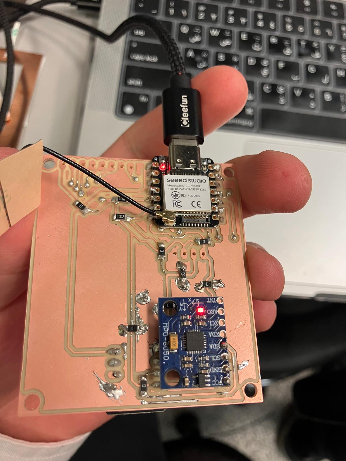
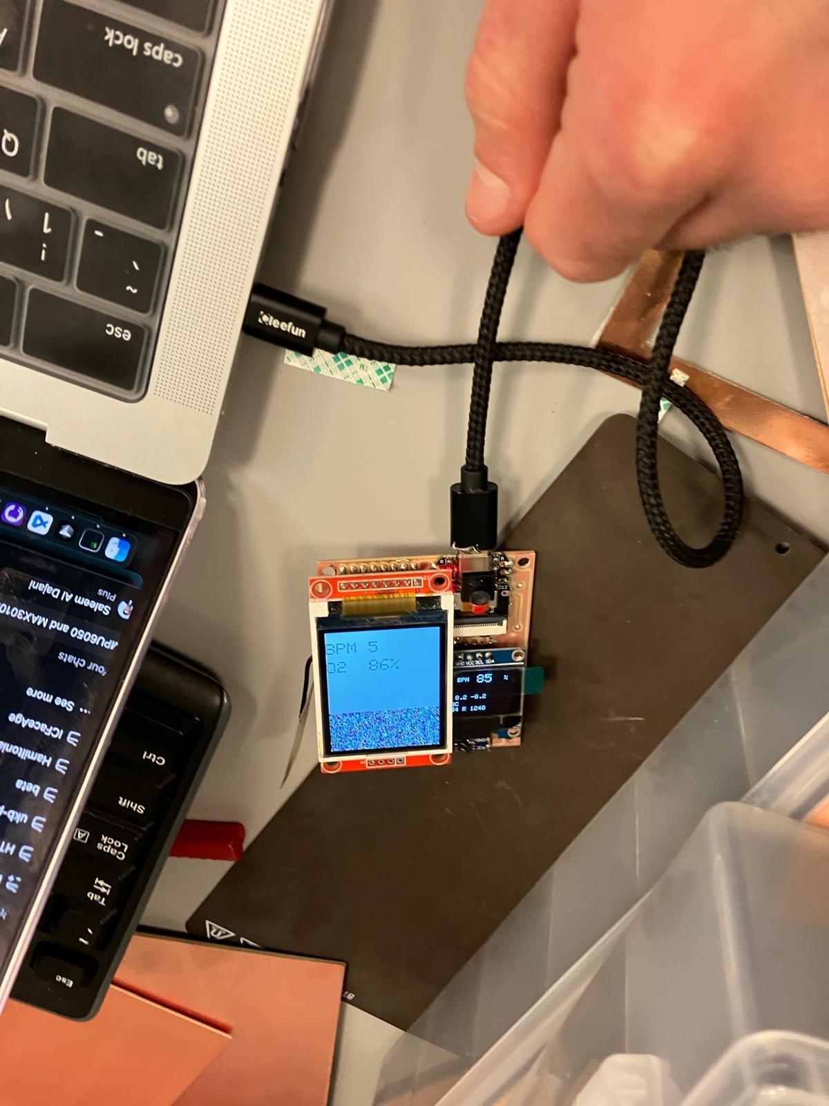
Final integration day focused on closing the watch subsystem, soldering and verifying all double-sided boards, refining molded bands, and assembling the complete MirrorAge demo with both the aging clock and grip-strength subsystems fully wired and tested. Completed rivet installation for plated through-holes, sensor bring-up (accelerometer, pulse oximeter, OLED/TFT displays), and full system integration on the tensegrity demo table. The integrated system successfully demonstrated synchronized sensor readouts and display behavior across all boards.
Rivet Installation & Soldering
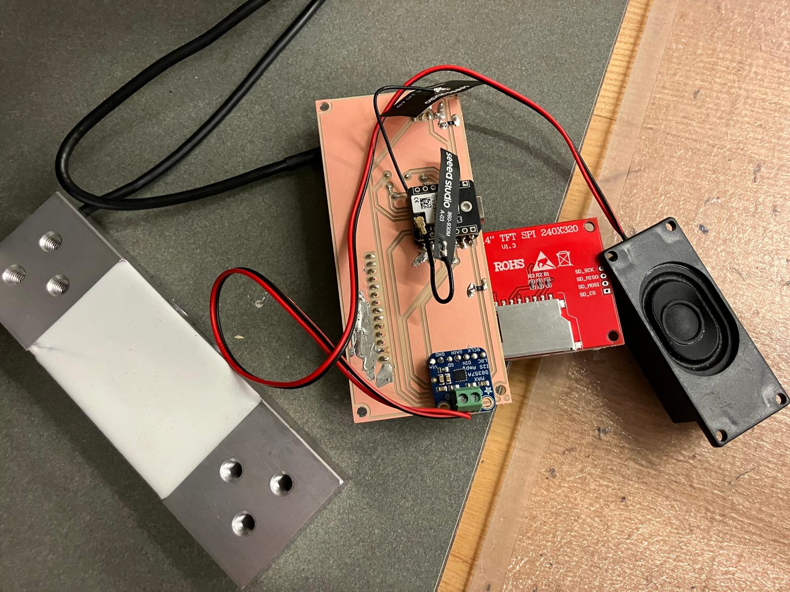
Sensor Testing & Bring-Up
System Integration
Day 6: Final Presentation
Final project presentation and demonstration of the complete MirrorAge system. Showcased the integrated aging clock and grip-strength subsystems working together on the demo table, demonstrating real-time sensor data collection and display synchronization. View final presentation demo →
Full Documentation: For complete details, design files, code, and comprehensive documentation of the system integration process, see Week 14: System Integration.
Final Project Masterpiece
Complete demonstration of the integrated MirrorAge system showcasing all subsystems working together in real-time; the required HTMAA final project questions are answered in the Answering Questions section below.
Final Presentation Demo: Complete MirrorAge system demonstration showing the integrated aging clock and grip-strength subsystems operating together on the demo table, with synchronized sensor readouts and real-time display updates across all boards.
1 Minute Video and 1 Slide Summary
Condensed 1-minute video and 1 slide summary showcasing key features and functionality of aging clock device system.
Design Files
Complete repository of all design files, CAD models, schematics, PCB layouts, firmware, and fabrication files from Week 0 through Week 14, organized by week and component type.
Note: Additional design files, firmware, and documentation can be found in the respective week pages. Some files are part of larger archives (ZIP files) that contain multiple related design files. The 3D printed watch casing and band geometries used in MirrorAge were adapted and scaled 2:1 from the open-source MutantW V2 ESP32-S3 smartwatch design, documented in the MutantW V2 repository, MutantW V2 Instructables guide, and associated Arduino community thread.
Reflections & Learnings
Comprehensive reflections on the MirrorAge Intrinsic Capacity Mirror project development journey.
Key Points
- Multimodal sensor fusion enables comprehensive intrinsic capacity assessment across WHO-defined domains
- Modular system design allows for incremental development and component-level testing throughout the semester
- Integration of mechanical, electrical, and software subsystems requires careful planning and coordination
- Iterative design and prototyping revealed the importance of early testing and validation
- Documentation and knowledge transfer are critical for project continuity and future improvements
- The project successfully demonstrates how digital fabrication and embedded systems can create meaningful health assessment tools
Contributions
Acknowledgements and contributions that made this project possible.
Gladyshev Lab and Collaborators
Special thanks to the Gladyshev Lab and collaborators for the fruitful discussions that led to this multimodal intrinsic capacity assessment idea, which supplements my PhD research goals in aging and longevity. The conceptual framework for integrating multiple digital biomarkers to assess intrinsic capacity domains emerged from collaborative research discussions on aging biomarkers and healthspan assessment.
Ethical AI Use
Transparent documentation of AI assistance used in this final project work, following course guidelines for ethical AI usage.
📋 General Guidelines: See General Commands for Cursor on the homepage for standard guidelines and commands used consistently throughout documentation development.
Cursor · Project Plan & Weekly Schedule
Comprehensive Cursor AI assistance for outlining the project plan and weekly schedule, including documentation structure, content organization, systematic updates across all week pages and the final project page, media integration, and summary generation workflows.
Cursor · Week 14 & Final Project Documentation
End-of-semester Cursor AI support for Week 14 system integration and finalproject.html polishing, including aging clock bring-up wording, Answering Questions cross-links, ethical AI notes, and BOM consistency checks.
The full session log is archived as markdown and converted to styled HTML using the course md_to_html_converter.py script.
Cursor · Final Project and Week 14 HTML Images
Cursor AI assistance for updating finalproject.html and week14.html, including adding the summary slide side-by-side with the one-minute video, and reorganizing the Serial Bring-Up sensor testing section with new image order and combined captions. The full conversation is preserved as a markdown transcript and a styled HTML view generated with scripts/md_to_html_converter.py.
Cursor · MutantW V2 Smartwatch Resources
Dedicated Cursor AI session used to collect, summarize, and cross-check open-source resources for the MutantW V2 ESP32-S3 smartwatch, including the GitLab project, Instructables build guide, and Arduino community thread. This assisted with documenting the 2:1 scaled watch casing and band design adaptation and ensuring proper attribution in the 3D printing and design-files sections.
The full conversation is archived as a markdown transcript and converted to styled HTML using the scripts/md_to_html_converter.py tool.
Cursor · Final Project Section Refresh
Cursor AI aligned the midterm review plan with updated system diagram, timeline, and remaining-task summaries, then refreshed finalproject.html to remove legacy bioprinting language and re-point internal links. The full transcript and generated HTML are available for review.
Cursor · Add White Background to Photo
Cursor AI assistance for adding a white background behind the photo in the Final Project Spiral Development Model section on finalproject.html. The image container was updated with white background, padding, and rounded corners for improved visual presentation.
Cursor · Midterm Final Project Update
Cursor AI distilled Week 0–9 documentation and the Oct 31 lab meeting deck into midterm-ready narrative, cost, and validation content, replacing every placeholder in finalproject.html.
Transcript archived in markdown and HTML (generated via scripts/md_to_html_converter.py) for transparency.
AI-Assisted Intrinsic Capacity Research & Design
ChatGPT was used to research and develop the multimodal intrinsic capacity assessment framework, including the comprehensive coverage analysis table and technical pipeline design. The AI assisted with structuring the WHO-defined intrinsic capacity domains, identifying appropriate digital biomarkers, and designing the fusion architecture for multimodal data processing.
AI-Assisted Final Project Development
Cursor AI assisted with developing the complete final project page structure, implementing the multimodal intrinsic capacity assessment framework, and creating comprehensive documentation. The AI helped with HTML structure, responsive design, weekly system integration plans, and organizing the technical documentation for the complete biomarker assessment system.
AI-Assisted Final Project Presentation Structure
Cursor AI assisted with finalizing the project presentation structure to ensure full compliance with MIT Academy project presentation requirements. The AI helped implement all required sections including answering questions, design documentation, bill of materials, individual mastery requirements, course presentation structure, and spiral model development approach visualization.
AI-Assisted Camera System Development
ChatGPT was used to discuss camera system implementation strategies, image processing algorithms, and EdgeAI integration approaches. The AI assisted with understanding Floyd-Steinberg dithering implementation, touch sensor integration, and exploring TinyML deployment options for the XIAO ESP32S3 platform.
AI-Assisted Project Highlights and Camera Subsystem Development
Cursor AI assisted with adding the project highlights section featuring camera system achievements and creating a comprehensive camera subsystem section with detailed code implementations, video demonstrations, and EdgeAI integration documentation. The AI helped with HTML structure, responsive design, image processing explanations, and organizing the technical documentation for the complete camera system showcase.
Cursor · Final Project Documentation Update
Cursor AI assistance for final project documentation updates including system integration summaries, highlights, and final project masterpiece section. The AI helped create a comprehensive system integration section in finalproject.html with day-by-day summaries, added key images and videos from week14.html, integrated system integration highlights into the project highlights section, and created a final project masterpiece section with embedded video and YouTube link. The transcript was converted to HTML using scripts/md_to_html_converter.py for better browser viewing.
ChatGPT · Video Planning
ChatGPT assistance for planning the one-minute video demonstration of the MirrorAge system, including script development, key feature selection, narrative structure, and video production guidelines to showcase the integrated aging clock and grip-strength subsystems effectively.
ChatGPT · One Slide Summary Development
ChatGPT assistance for developing the one-slide summary based on email exchange with Prof. Vadim Gladyshev, including distilling key project achievements, technical highlights, and system integration outcomes into a concise visual summary format for the final project presentation.
 This work is licensed under a
Creative Commons Attribution-NonCommercial-ShareAlike 4.0 International License
This work is licensed under a
Creative Commons Attribution-NonCommercial-ShareAlike 4.0 International License