Final Project Tracker
Concept ~ actuated surfaces
The 3D printing exercise inspired me to reconsider my final project idea. I have been interested in exploring friction
as a design parameter: I think it could be interesting to develop a surface with actuatable/modulatable texture ~ like a smart velcro:
a surface that could go from having adhesive properties to non-adhesive. The final project 'object' should explore this concept e.g. perhaps in the
form of a reconfigurable/self-assembling robot (i.e. the surfaces can adhere and release in a programmable manner, thus rearranging themselves).
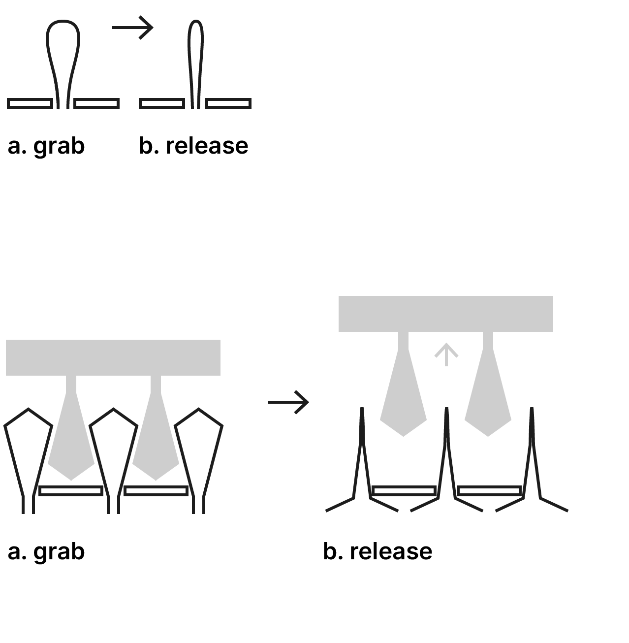
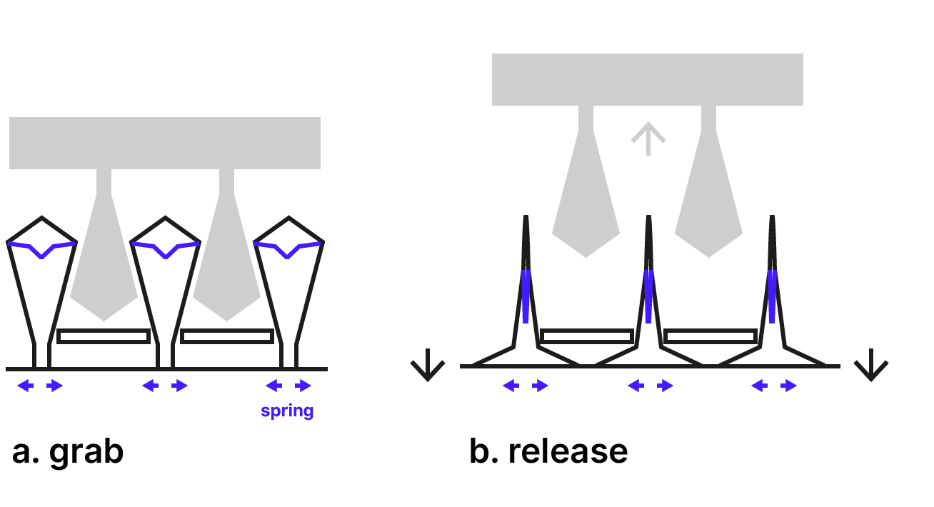
Actuated velcro concept sketches; bi-stable snap-fit experiment from wk01 and 3D print experiments from wk03
Sketch of actuated velcro release by bending ...
Since I will definitely need a compact actuator of some kind, I have ordered a
small high-gear 6V motor from Pololu, and motor-driver from Pololu.
Next, I will develop some detailed designs of the different velcro concepts so that I can make some quick prototypes over the coming weeks.
Micro-motor and driver carrier board from Pololu.
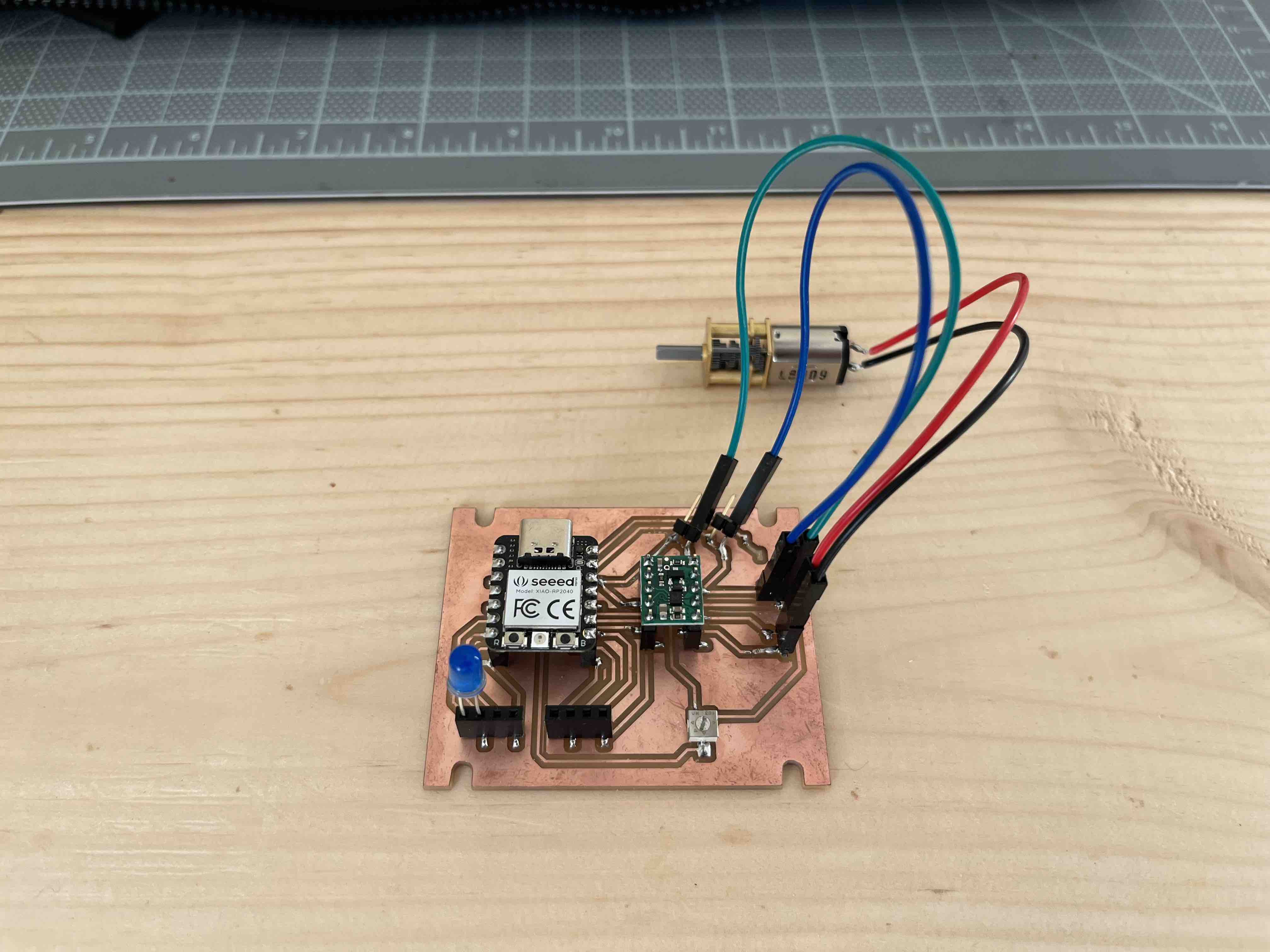 PCB from week 05, hooked up to the micr-motor. It seems to work well, just running off of the Vcc (5V) of the Xiao hooked up to my Mac.
29 October update ~ folded cardboard models exploring spring-loading and sketch with dimensions (mm) that seemed to work well for an initial prototype.
PCB from week 05, hooked up to the micr-motor. It seems to work well, just running off of the Vcc (5V) of the Xiao hooked up to my Mac.
29 October update ~ folded cardboard models exploring spring-loading and sketch with dimensions (mm) that seemed to work well for an initial prototype.
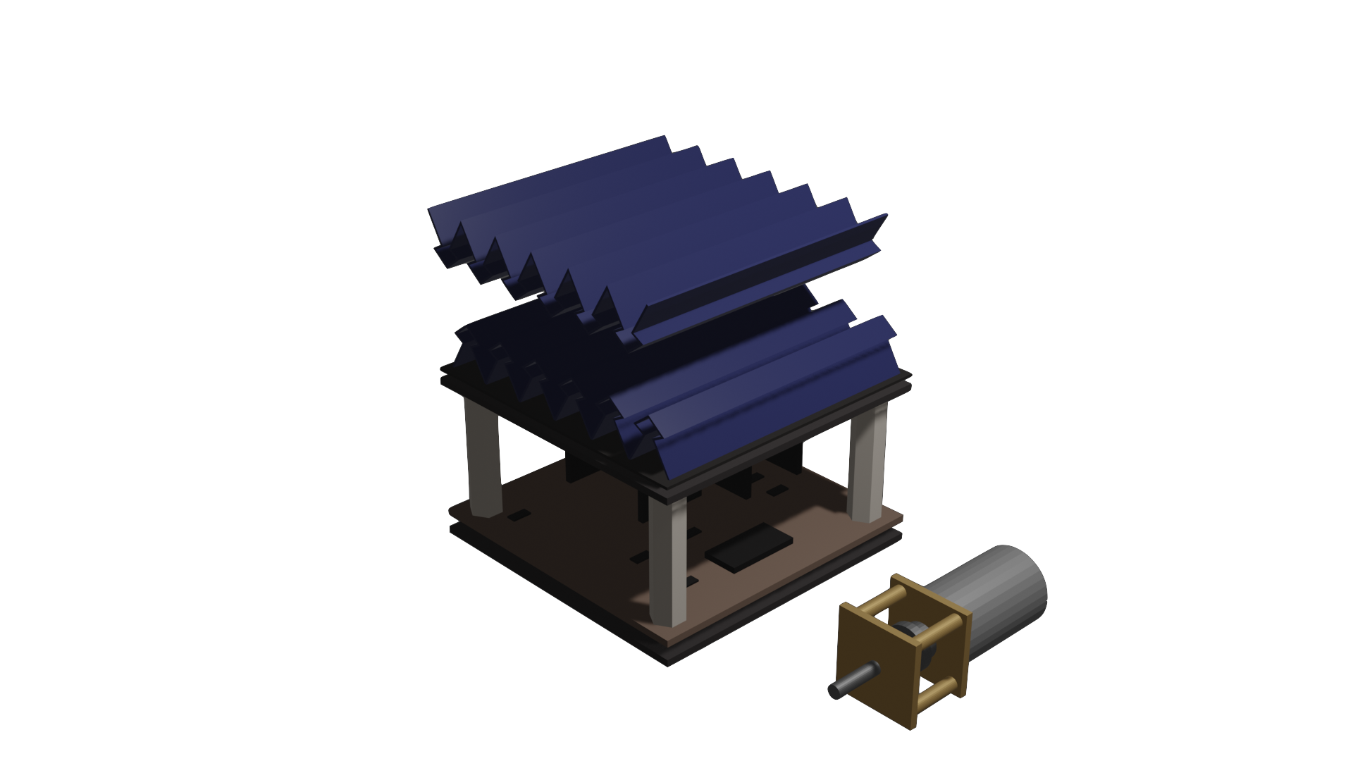
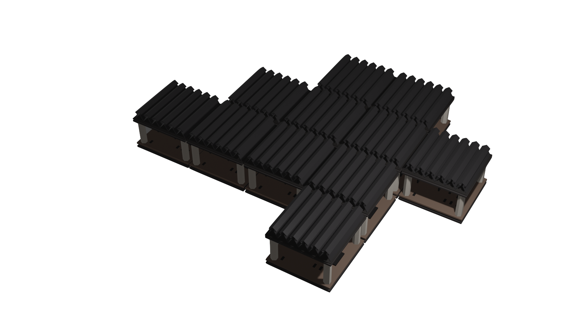 29 October update ~ 3D sketches in blender of unit actuated surface module.
Bi-stability
I think bi-stability will be an interesting concept to explore as a way of minimising the power requirements of the actuation (i.e. using a motor only as a way to
'toggle' between two stable states, by overcoming some activataion energy, e.g. a spring or the elasticity of a compliant material). While googling bistability, I found
some interestnig papers in the field of metamaterials, describing geometries that can be reconfigured into different stable states.
Twist-tie experiments
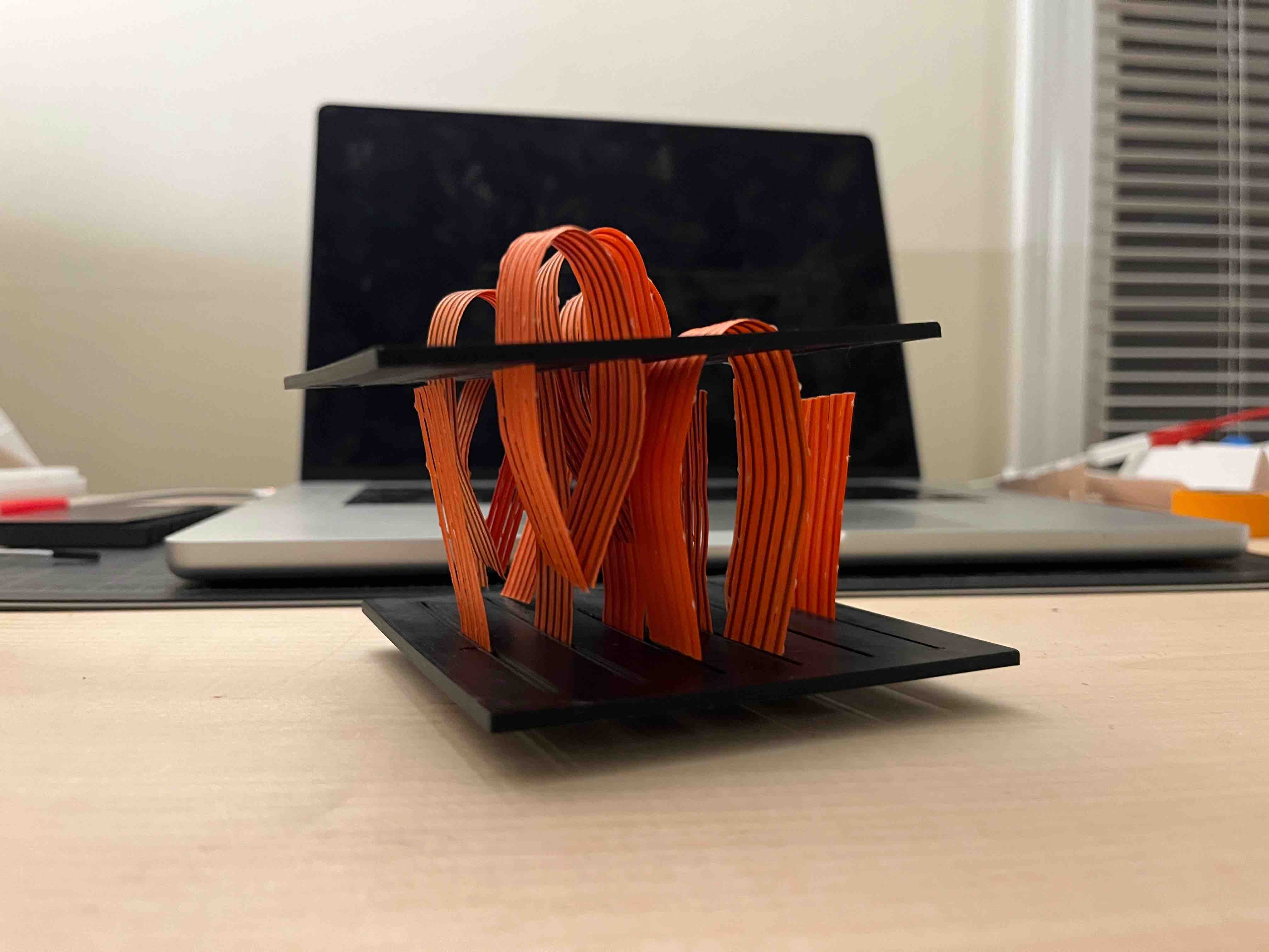
 Twist tie velcro prototype with a passive (straight 'hairs') and active side (curved hairs).
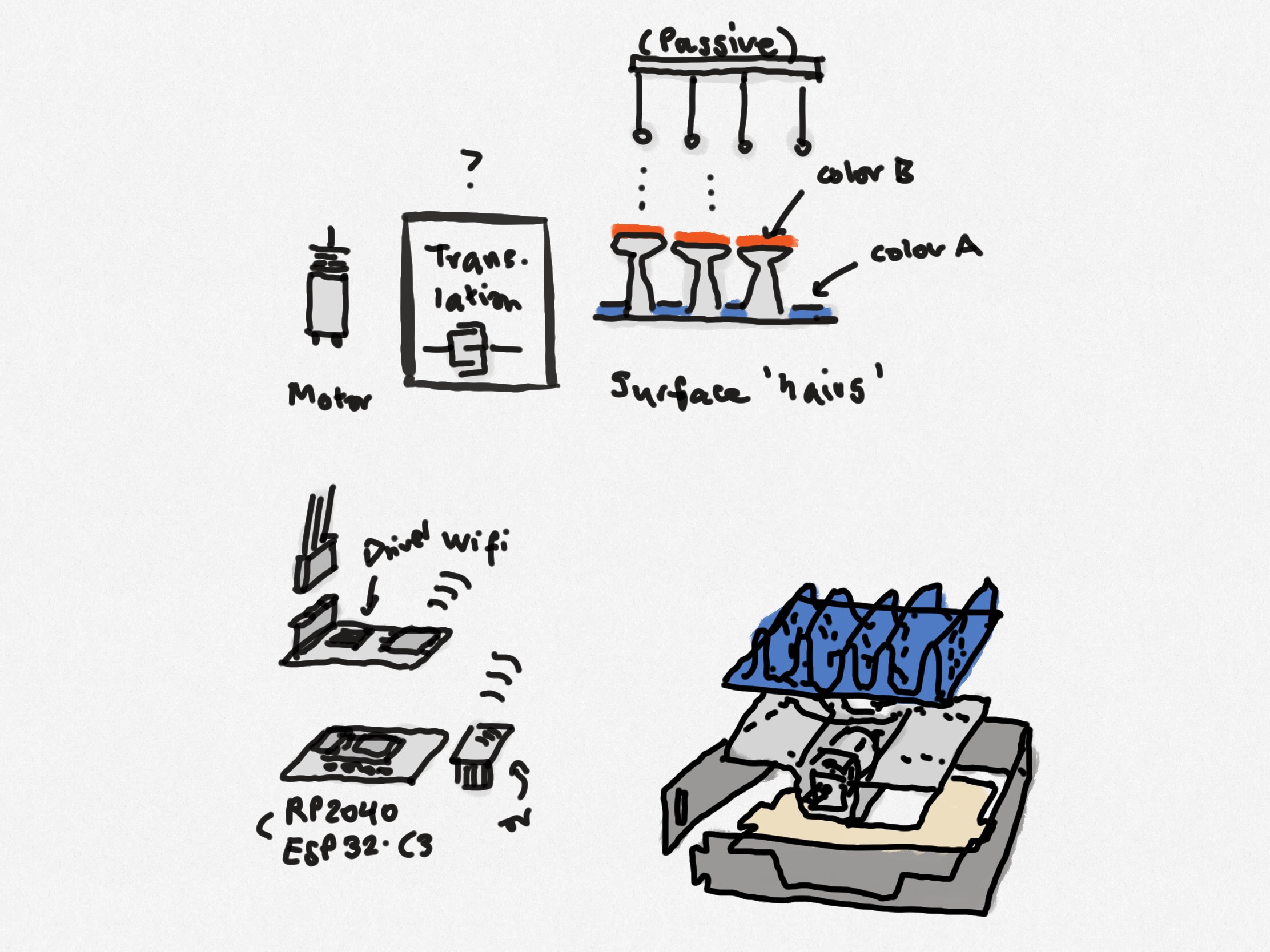 Sketch of some of the core components of the system. A major question is still how the translation will happen between the motor and the folded structures.
Translation motor-to-surface
To translate the rotary motion of the motor into vertical displacements, I was thinking it could be cool to use a helical kirigami pattern like the one described here.
I did some tests with a plastic sheet I had purchased from Blick (probably poloyproylene?), but will have to see if I can find a similar material that is suitable for laser-cutting/3D printing.
Electronics and communication
I based my motor driver circuit off of Neil's design
using the TB67H451A H-bridge. My final board incorporates headers to attach an NRF24L01 radio board and even a few thru-holes (to account for places I couldn't route
my out of - i.e. I will attach jumpers here for +5V and +3.3V). I have also incorporated a square cutout underneath the Xiao, to allow a battery to be connected from below.
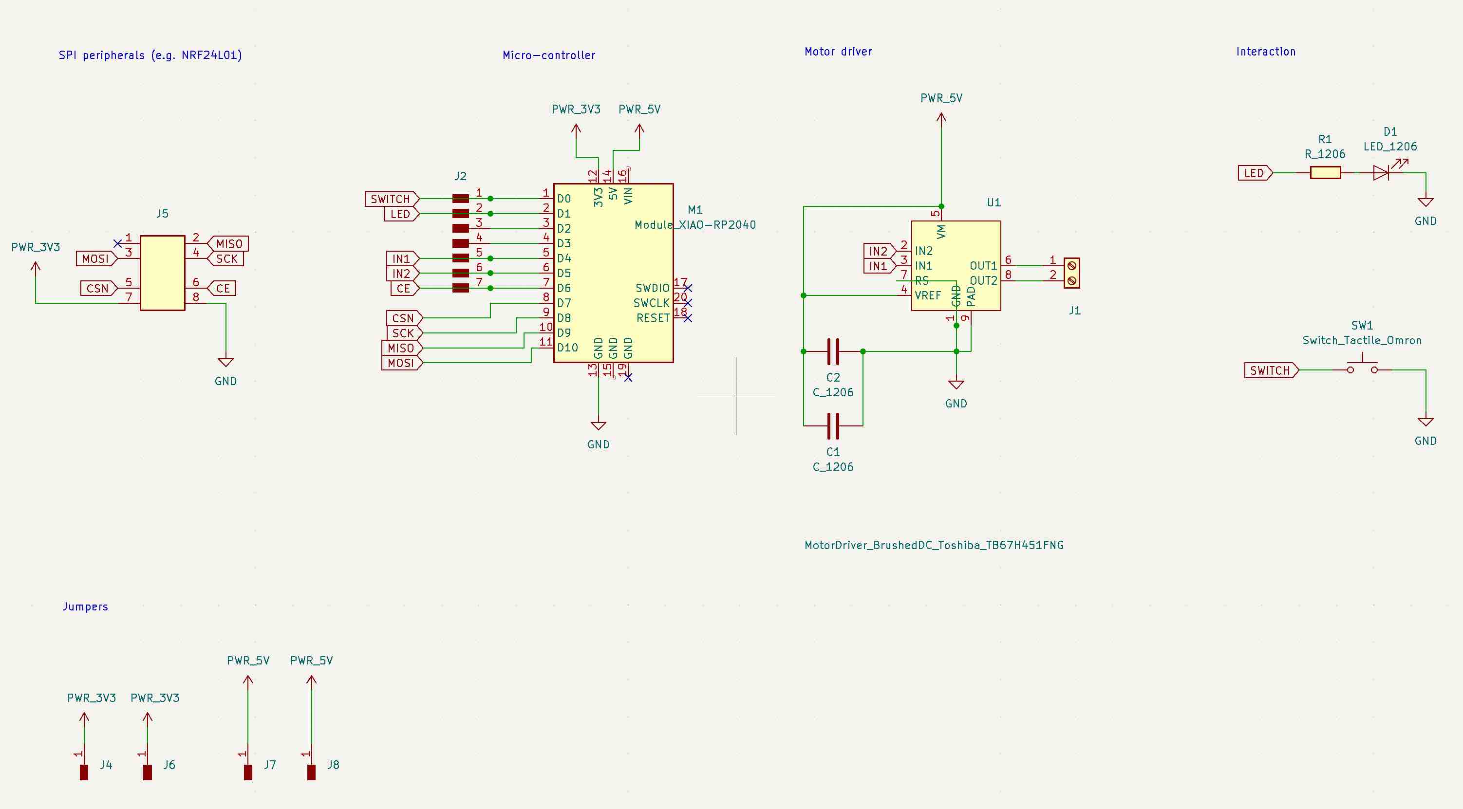 Final schematic with motor driver, wireless transceiver, button,
LED and mechanical features to allow for snap-fits of the outer structure and motor holders in the centre
(more details see networking week).
Updated traces, thru-holes (to allow for jumpers on the 3.3V and 5V lines) and edge-cuts with a cut-out in the middle to allow for battery power (in the future - and perhaps especially if the design is shifted towards ESP32).
Trying to fabricate two boards at once (bundling trace and edge cuts), but without sufficient fixation to the bed (board on the right).
Sending serial commands to one of the modules, which will act as the controller to send wireless commands
to the other peripheral modules. More details: interface week and networking week.
Final schematic with motor driver, wireless transceiver, button,
LED and mechanical features to allow for snap-fits of the outer structure and motor holders in the centre
(more details see networking week).
Updated traces, thru-holes (to allow for jumpers on the 3.3V and 5V lines) and edge-cuts with a cut-out in the middle to allow for battery power (in the future - and perhaps especially if the design is shifted towards ESP32).
Trying to fabricate two boards at once (bundling trace and edge cuts), but without sufficient fixation to the bed (board on the right).
Sending serial commands to one of the modules, which will act as the controller to send wireless commands
to the other peripheral modules. More details: interface week and networking week.
Mechanical explorations
Quick mechanical concept: translating rotation in the horizontal plane into vertical motion using a spiral kirigami pattern. The rotation of the top would have to be constrained somehow to force the upwards expansion.
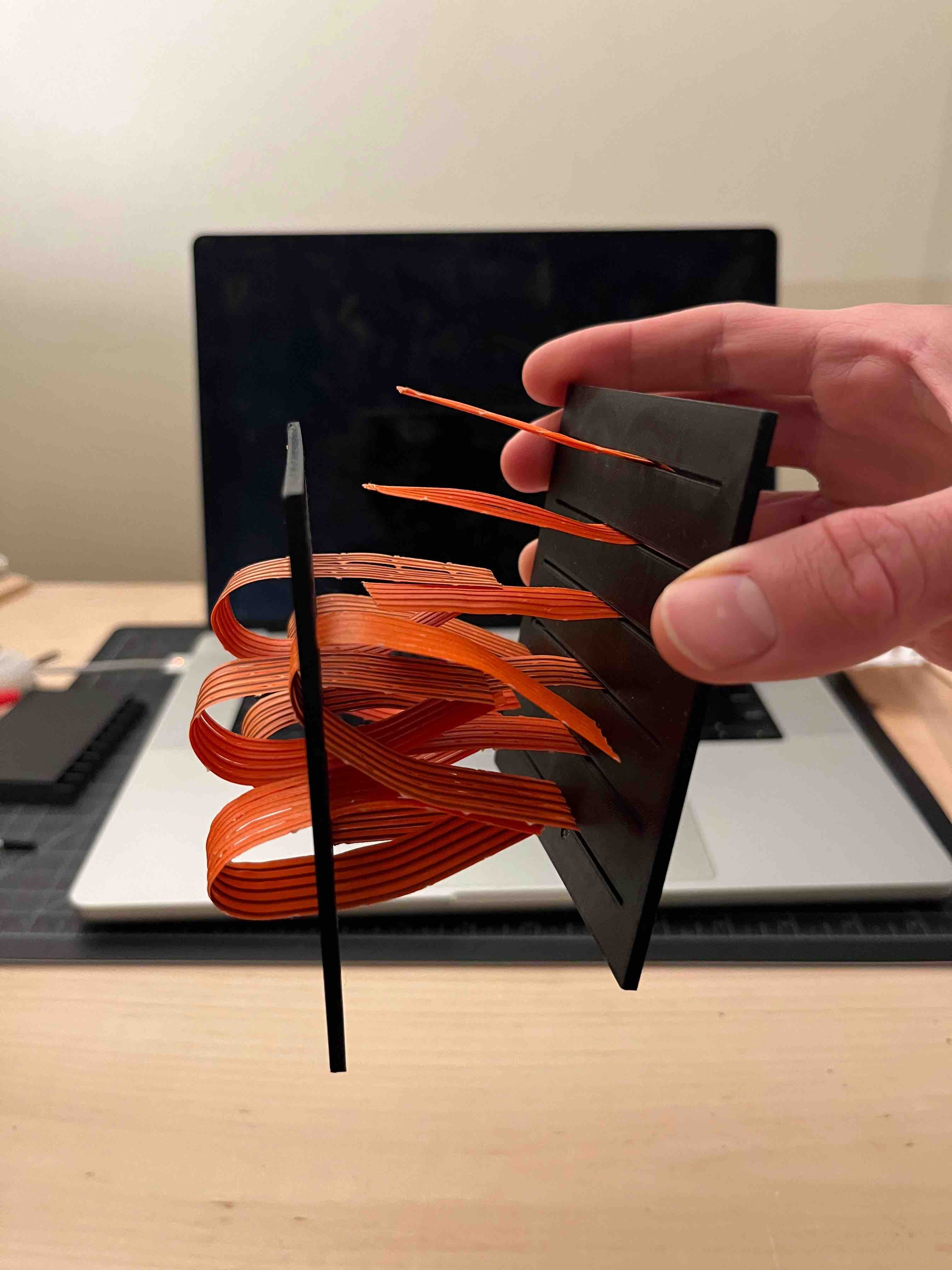
Twist-tie velcro release.
Prototyping an actuated surface on an alternative version of the module frame.
Testing of the motor.
Assembly
The idea is to have a module that can allow for the prototyping and actuation of many tpes of surfaces. Everything mounts on the PCB and I placed components with mechanical
flexibility in mind: e.g. the micro-motor can be mounted either vertically or horizontally oriented and allow attachments are reversible snap-fits (provided the 3D prints don't break).
Horizontal and vertical motor holders, mounted on the (P)CB.
Four modules with different motor arrangements; snap fit detail (somewhat inspired by the connectors I made during large-format machining)
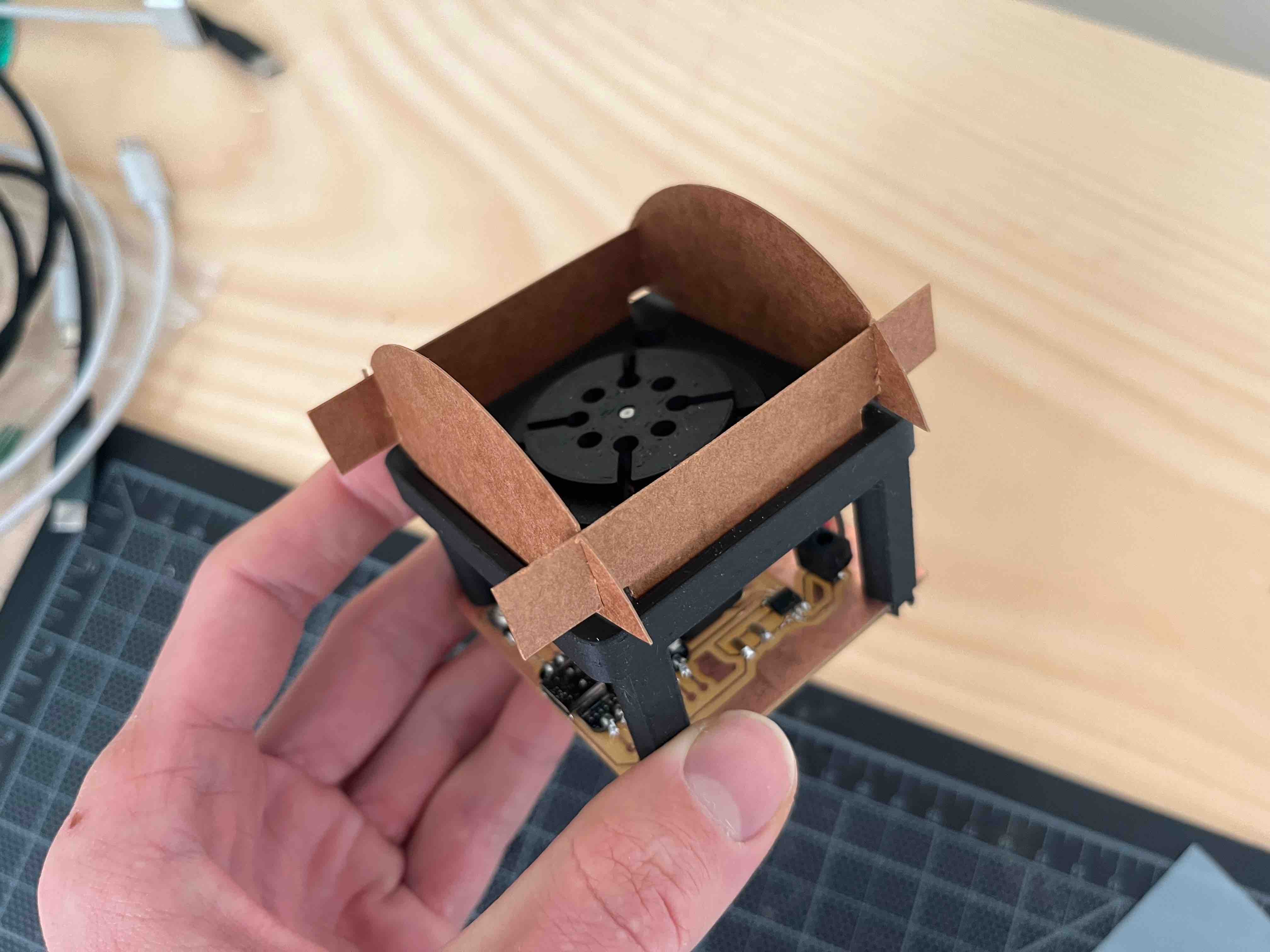 Example cardboard construction using the grooves in the top-plate of the module.
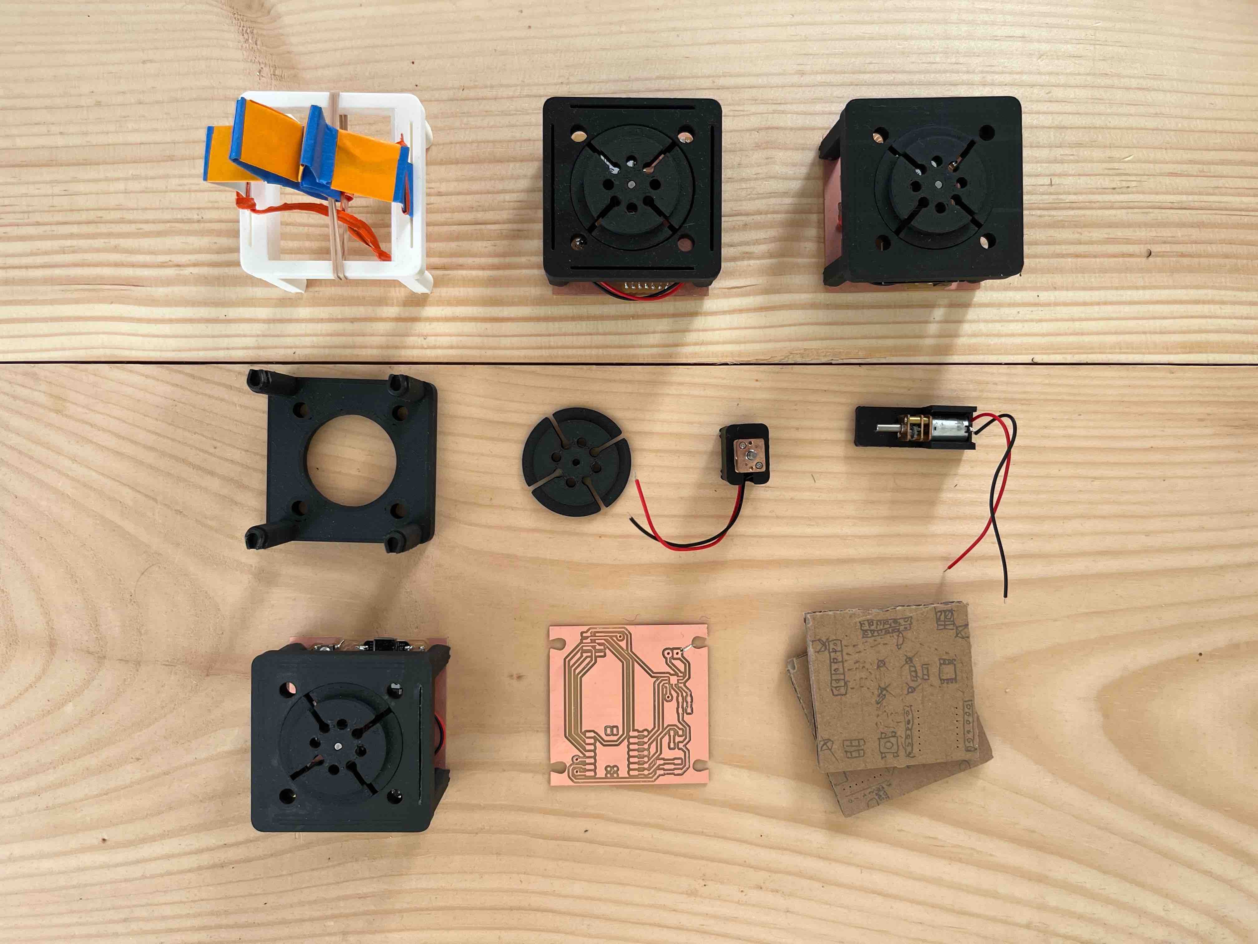 Module prototypes with motor attachments and early cardboard PCB models to figure out motor/component placement on the board.
Bill of materials
Per module:
- Micromotor (from Amazon ~ 4 USD)
- Xiao RP2040 (~10 USD)
- NRF24L01 wireless transceiver (Amazon ~ 2 USD)
- TB67H451FNG H-bridge motor driver (Digikey ~1.50 USD)
- surface mount LED (Digikey ~0.3 USD)
- tactile switch (Digikey, ~0.3 USD)
- screw connector terminal (Digikey, ~1.2 USD)
- resistors, capacitors (total ~0.5 USD)
- FR-4 copper board (from Amazon, ~0.7 USD)
- 35 g PLA filament, 3D printing (~1 USD)
---------
~ 22 USD
Summary
I started with the idea of creating programmable velcro-like surfaces that could be actuated to grab and release.
The design of the surfaces themselves turned out to be more time consuming than expected (many options ~ origami, kirigami, flexures, etc).
I knew however that I would need a simple and compact way of actuating them. As such, this project has evolved into more of a starting point for
further research: I have tried to develop a tool that I can use as the basis for prototyping these surfaces.
Next time, I would definitely try to embrace the 'spiral development' cycle earlier - it would have been nice to have had one fully-actuated surface working.
However, I'm still quite pleased with the result; I think it is a well integrated design with nice assembly details, incorporating snap-fits and utilising the circuit board
as a structural element. I feel quite motivated to push this idea further over IAP/next semester, especially as I still have 6 extra micromotors waiting to be used ...