Week 05 ~ Electronics Production
Milling the board
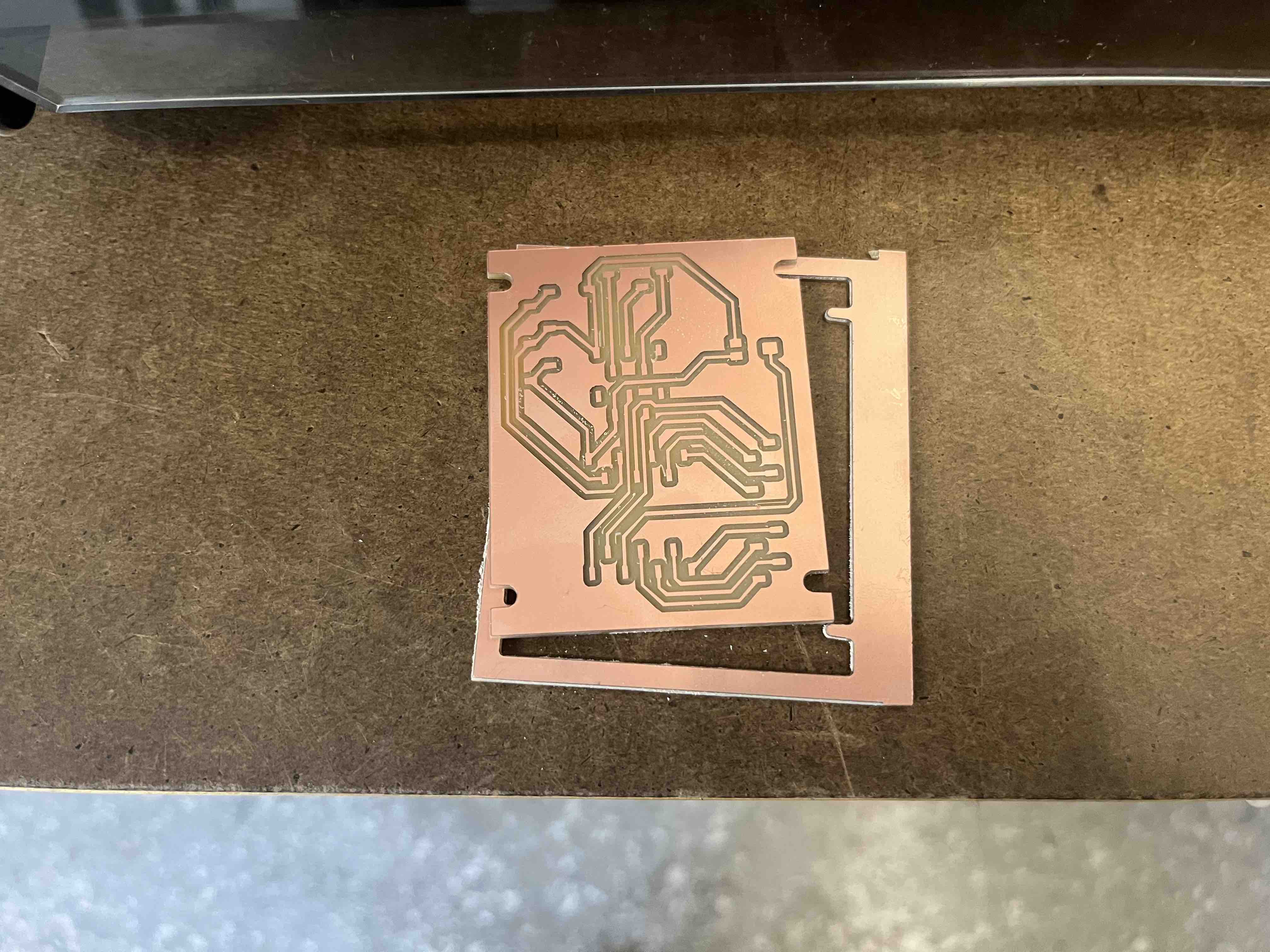
Before milling; traces milled (plus U-shaped outline that was somehow also exported)
Milling the outline of the board design from week04 on the Roland SRM-20. The workflow:
export separate .svg s from KiCAD for the traces and edge-cuts > import into Illustrator and export as .png s
> import into mods. For some reason illustrator includes a tiny white outline on the .png s when you export
- I noticed this too late so both the traces and edge-cuts started off with a U-shaped outline being cut..
 After milling
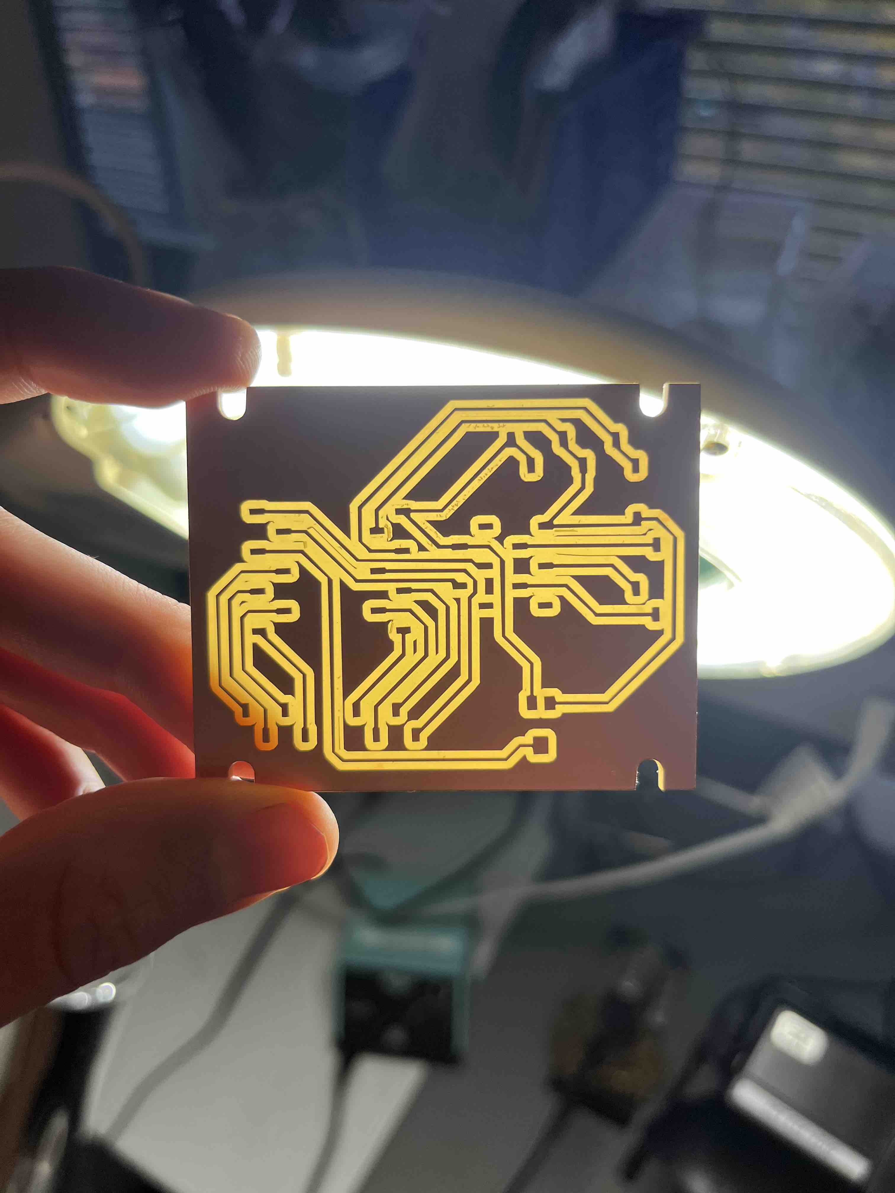 Backlit circuit ~ easier to see some of the irregularities in the traces; perhaps due to vibrations?
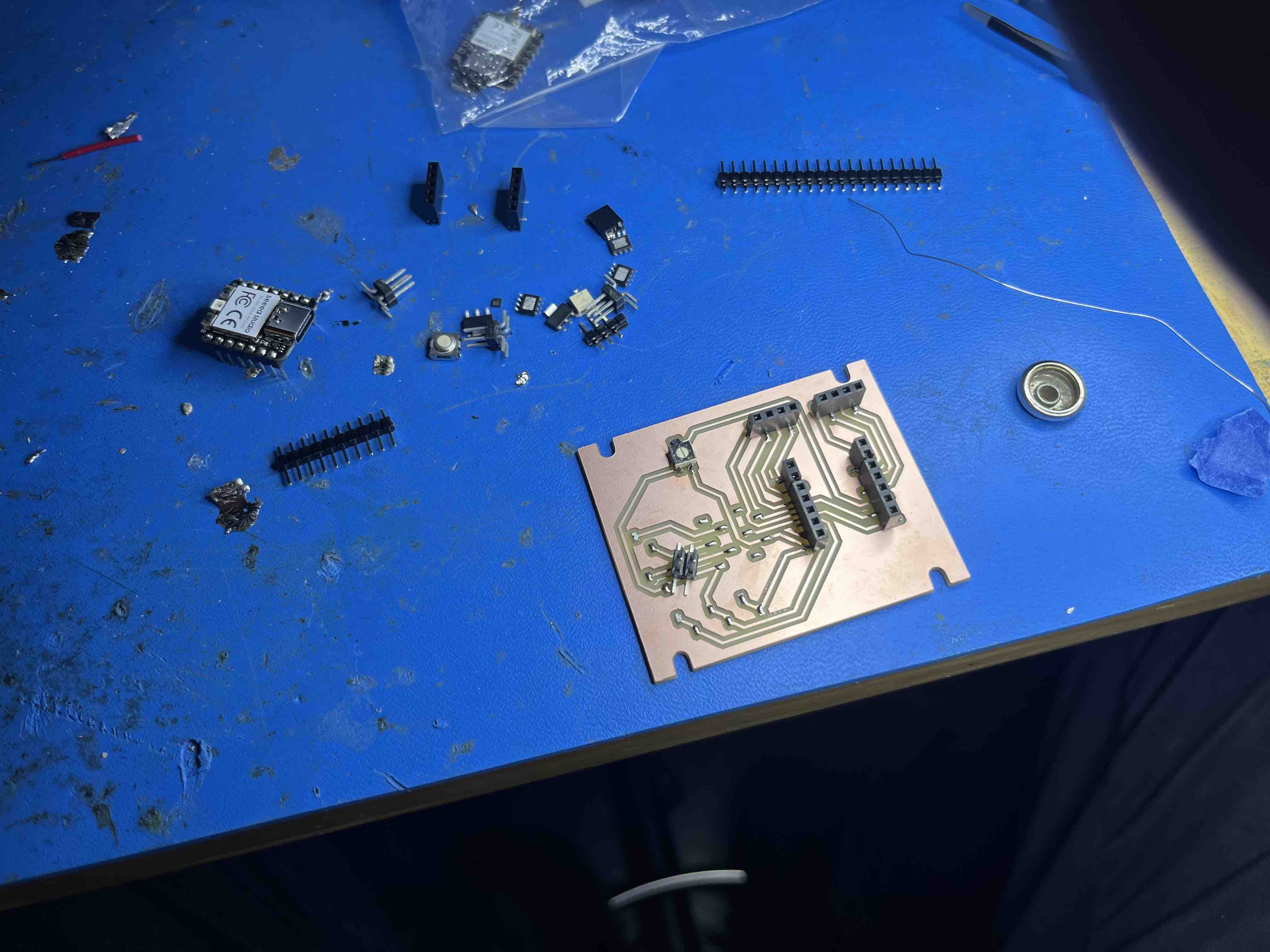 Soldering components ~
I clipped the Xiao into the headers while I soldered them, so that the fit/placement would be accurate.
I had ordered Pololu's DRV8838 breakout board
at the beginning of last week, but it seems the package was stuck in Washington DC somewhere, which is why I decided to leave the pads for it unsoldered for now.
Thanks Anthony for helping source female headers in the EECS design studio and some helpful tips.
Adding solder to all the pads,
chopping headers ... (5+2 = 7 pin header)
Soldering components ~
I clipped the Xiao into the headers while I soldered them, so that the fit/placement would be accurate.
I had ordered Pololu's DRV8838 breakout board
at the beginning of last week, but it seems the package was stuck in Washington DC somewhere, which is why I decided to leave the pads for it unsoldered for now.
Thanks Anthony for helping source female headers in the EECS design studio and some helpful tips.
Adding solder to all the pads,
chopping headers ... (5+2 = 7 pin header)
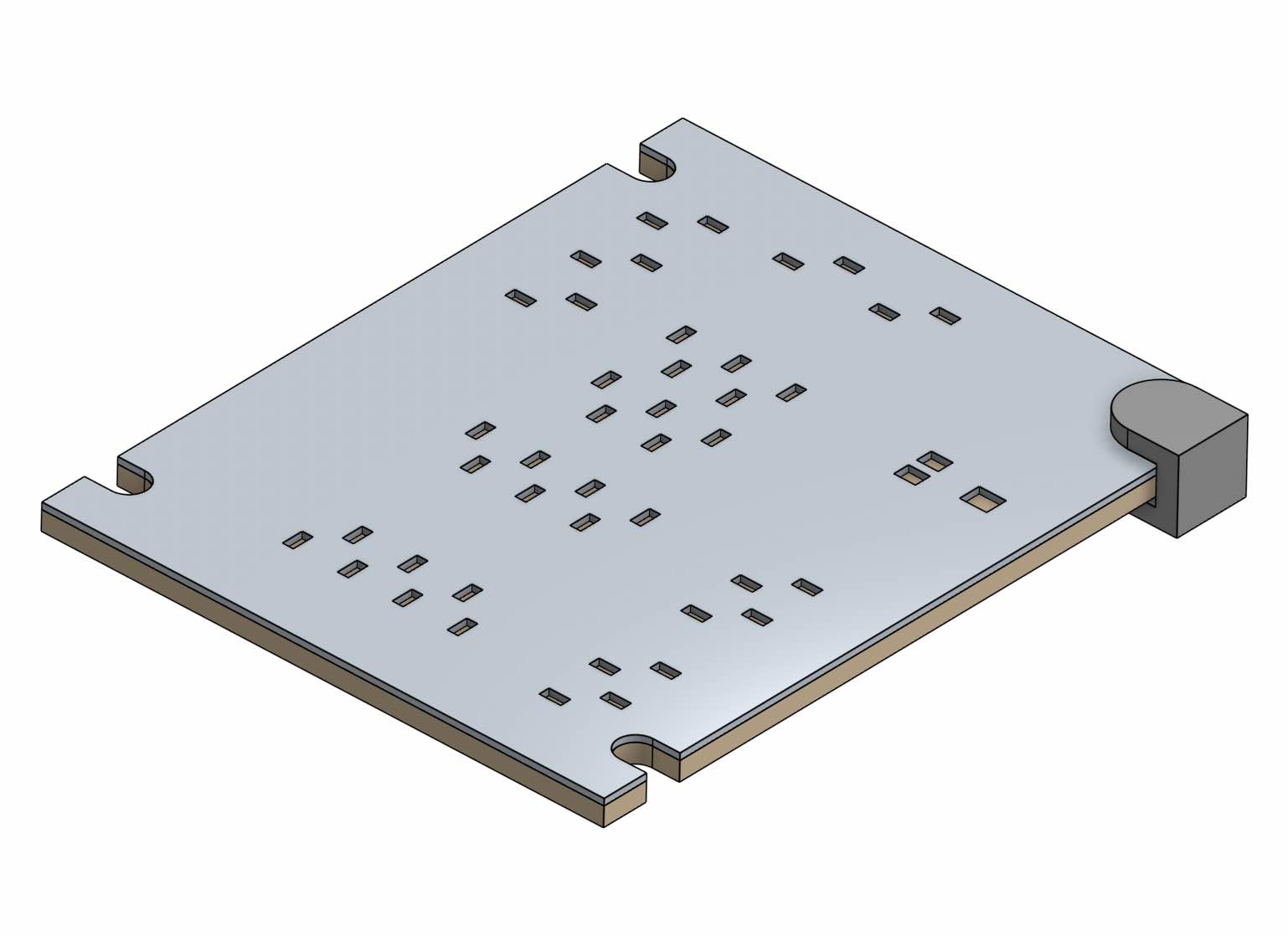 Sketch for a solder mask that I didn't get round to testing.
I used the following code to test the potentiometer and some of the pins I had broken out by connecting some LEDs I had lying around:
        /*
        Niklas Hagemann, HTMAA 2023 - PCB milling week test
        Adapted from the Arduino AnalogInput example (https://www.arduino.cc/en/Tutorial/BuiltInExamples/AnalogInput)
        */

        const int sensorPin = D2;
        const int ledPin = 25;
        const int yellow_led = D7;
        const int blue_led = D3;
        int sensorValue = 0;
        int led_state = LOW;

        void setup() {
          Serial.begin(9600);
          pinMode(ledPin, OUTPUT);
          pinMode(yellow_led, OUTPUT);
          pinMode(blue_led, OUTPUT);
        }

        void loop() {

          sensorValue = analogRead(sensorPin);
          digitalWrite(ledPin, HIGH);
          delay(sensorValue);
          digitalWrite(ledPin, LOW);
          delay(sensorValue);

          //  if (sensorValue > 500) {
          //    Serial.print("Reading: ");
          //    Serial.println(sensorValue);
          //    led_state = HIGH;
          //  }
          //  else {
          //    led_state = LOW;
          //  }

          digitalWrite(yellow_led, led_state);
          digitalWrite(blue_led, !led_state);

          // to make it swap colors, delay depends on pot value
          delay(sensorValue);
          led_state = !led_state;
        }
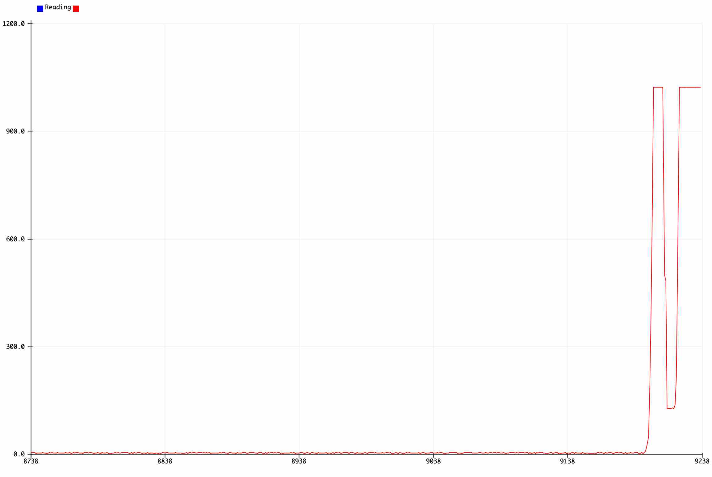 Arduino serial plotter - analog readings from the potentiometer connected to D2.
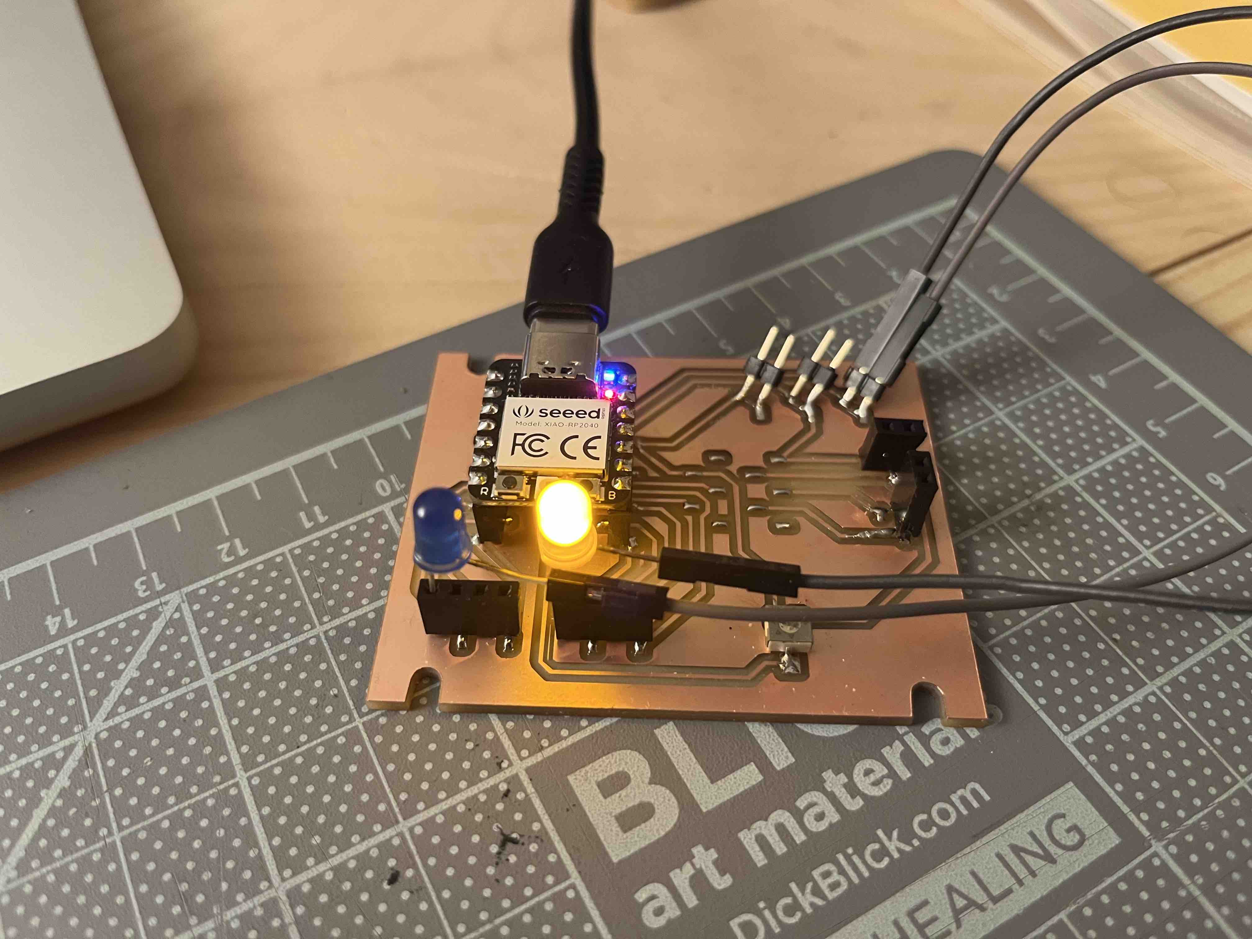 Testing the pins; swapping between LEDs at a rate depending on the pot input.
The trim pot turned out not to be very easy to adjust, next time I might go for a larger form-factor.
Blinking LEDs ...
Attaching a vibration motor ...
Testing the pins; swapping between LEDs at a rate depending on the pot input.
The trim pot turned out not to be very easy to adjust, next time I might go for a larger form-factor.
Blinking LEDs ...
Attaching a vibration motor ...
The main takeaways from this week for me were about header placement: as Anthony had pointed out, soldering 2-pin headers with an offset footprint is hard as there's no way
for the header to stand on the board by itself. Furthermore, I tore off the copper pads in two locations as I applied too much force attaching jumper cables - I would assume that larger headers could also help with,
as the force would be distributed across a larger area. In future it would also be helpful to break out more ground pins and place them closer to the other breakout pins; all
of which suggests going for larger headers next time ...
Files: see week 04