Week 09 ~ output devices
Controlling a bunch of micro-motors
For my final project I will be controlling a number of micromotors.
Previously, I had tested a DRV8838 breakout board from Pololu, this worked fine - however I wanted to go smaller, so looked at Neil's design
for a driver circuit using the TB67H451FNG H-bridge.
More details on the PCB design can be found in my final project tracker.
Pin assignment and logic output table (source: Toshiba)
The H-bridge can drive a single motor, with the operating principle being quite simple (see logic table above from the data sheet) - taking one input pin high
and the other low makes the motor spin in one direction; doing the reverse, reverses the output polarity and makes the motor spin the other way. Pulling both
low does nothing (i.e. a 'gradual' stop), while pulling both high, short circuits the motor, creating a braking force in the coils.
Taking Neil's design as a starting point, I added a button and LED to give some ways of interacting with the board once programmed. After milling the board and soldering
all the components I uploaded a simple Arduino sketch (see below) that turns the motor when you press the button, switching direction each time.
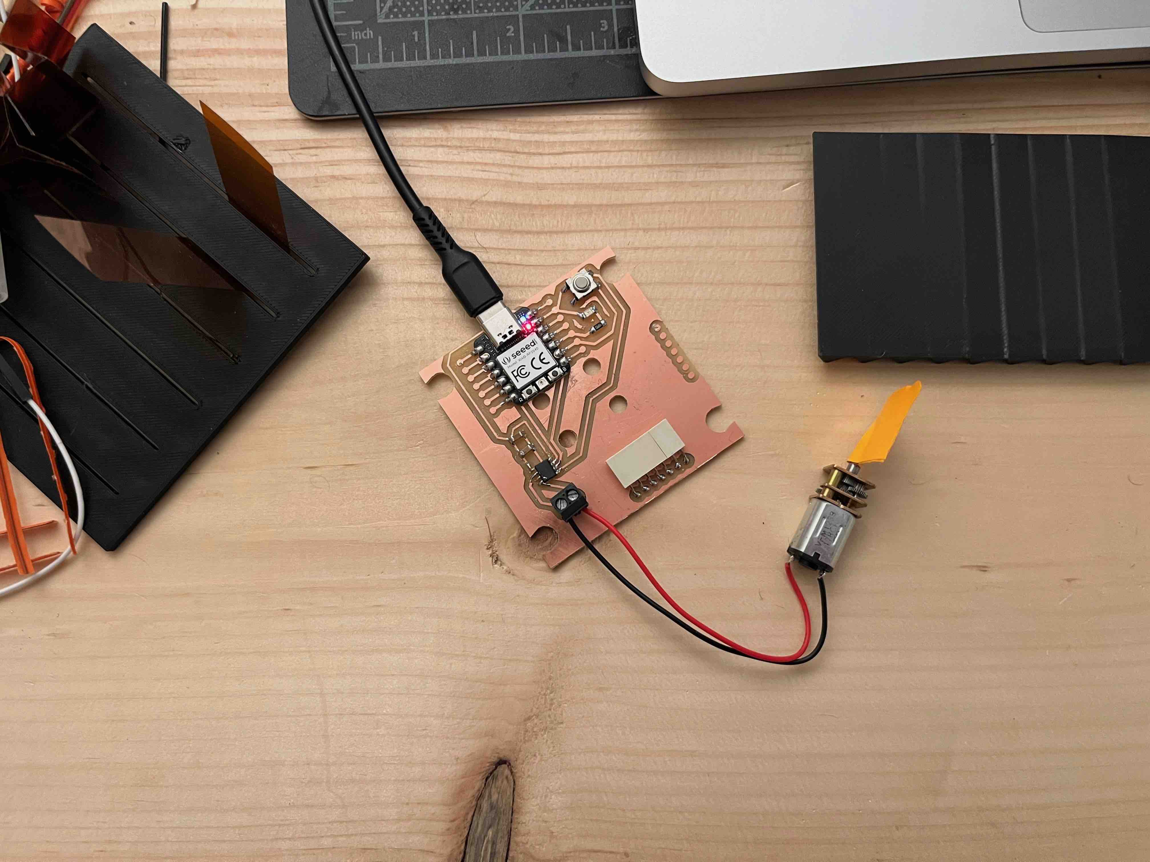 Milled board; checking the voltages at different parts of the circuit
to understand if the soldered circuit is behaving as expected (yes!); motor hooked up to the screw terminals.
The holes in the centre of the board will allow the motor to be mounted in different orientations.
Milled board; checking the voltages at different parts of the circuit
to understand if the soldered circuit is behaving as expected (yes!); motor hooked up to the screw terminals.
The holes in the centre of the board will allow the motor to be mounted in different orientations.
// HTMAA 2023
// Niklas Hagemann
// Motor driver

// interface
#define BUTTON_PIN D0
#define LED_ORANGE D1

// H-bridge motor control, using the TB67H451FNG, should run with input 2-5V
// I'm using geared micro-motors bought from Amazon, specced at 3-7V (~30rpm).
#define FORWARD_PIN D4
#define BACKWARD_PIN D5

uint8_t dirn = 1;       // direction, 1 or 0.
uint8_t state = 0;      // state variable, so we can change direction when there is a new state.

void setup() {
  pinMode(BUTTON_PIN, INPUT_PULLUP);
  pinMode(LED_ORANGE, OUTPUT);
  pinMode(FORWARD_PIN, OUTPUT);
  pinMode(BACKWARD_PIN, OUTPUT);
}

void loop() {
  uint8_t user_input = digitalRead(BUTTON_PIN);

  if(user_input == LOW) {
    if (state == 0) {
      state = 1;
    }
    digitalWrite(LED_ORANGE, HIGH);
    // spin motor forward
    digitalWrite(FORWARD_PIN, dirn);
    digitalWrite(BACKWARD_PIN, !dirn);
  }
  else {
    if (state == 1) {
      dirn = !dirn;       // if we've just changed state, change the direction
      state = 0;
    }
    digitalWrite(LED_ORANGE, LOW);
    // stop motor
    digitalWrite(FORWARD_PIN, LOW);
    digitalWrite(BACKWARD_PIN, LOW);
  }
  delay(100);             // wait for physical things (e.g. button) to settle.
}
Testing the circuit.
Files: traces.png, holes.png, edge_cuts.png