Week 04 ~ Electronics Design
Designing a dev board for the Xiao RP2040
I decided to go with KiCad for my board design. I like that it's free and I've used it once or twice to design some very basic boards,
though I definitely needed a refresher. I downloaded the latest version from the KiCad website and followed the instructions to install the fab component library.
For my final project, I will eventually need actuation of some sort. In the fab library, there are a couple of H-bridge motor drivers, including the DRV8838, for which
Pololu also makes a compact breakout board.
Schematic for Pololu's DRV8838 breakout board (source: Pololu); Truth table for the DRV8838, showing what pins need to be set high and low to spin the motor forward/backwards/at different speeds (source: Pololu)
Originally I wanted to use the chip directly, but the Pololu board seems like a nice package to work with, so I thought
this could be a good opportunity to learn how to make custom footprints in KiCad.
I found this Digikey video helpful for the overall workflow, although some of the details
around designating new component libraries seem to have become simpler since the video was created.
Creating a new footprint for the Pololu breakout board,
by duplicating the 01x05 PinHeader footprint from the fab library.
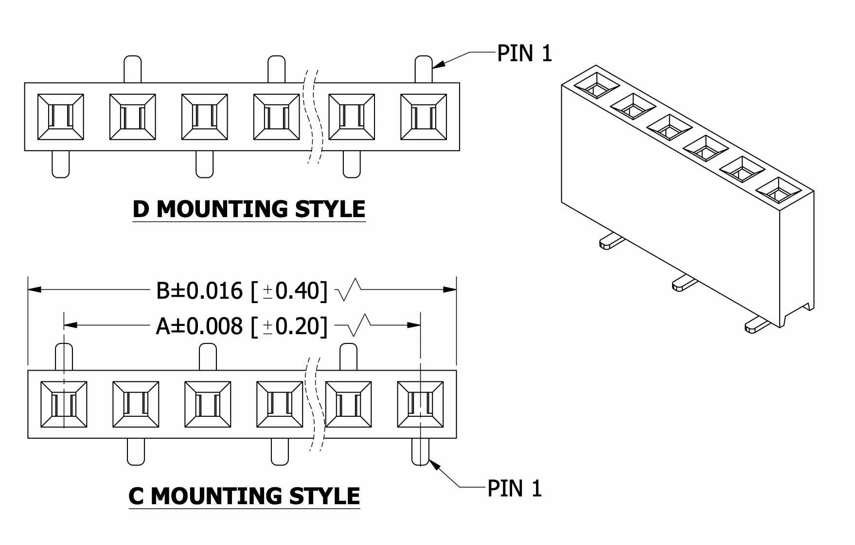 To make both the Xiao and Pololu boards detachable, I will use vertical surface-mount pin-headers (source: Digikey)
After creating the footprint, I also created a new schematic symbol to represent the Pololu breakout board. The Digikey video
from the same series was helpful.
Creating a new schematic symbol for the Pololu breakout board. In contrast to some of the other component symbols I've seen,
I wanted the symbol to reflect the actual physical location of the pins on the breakout board, so that it might be easier to anticipate the way thing would be routed later.
Next, it was finally time to make the schematic ... In addition to the motor-driver, I broke out the reamining digital pins from the Xiao, and points
for GND, 5V and 3.3V. I also added a 10K "trim-pot" potentiometer from the fab inventory and connected it to one of the analog pins on the Xiao, with the
idea that this could be an easy way to tune motor speed.
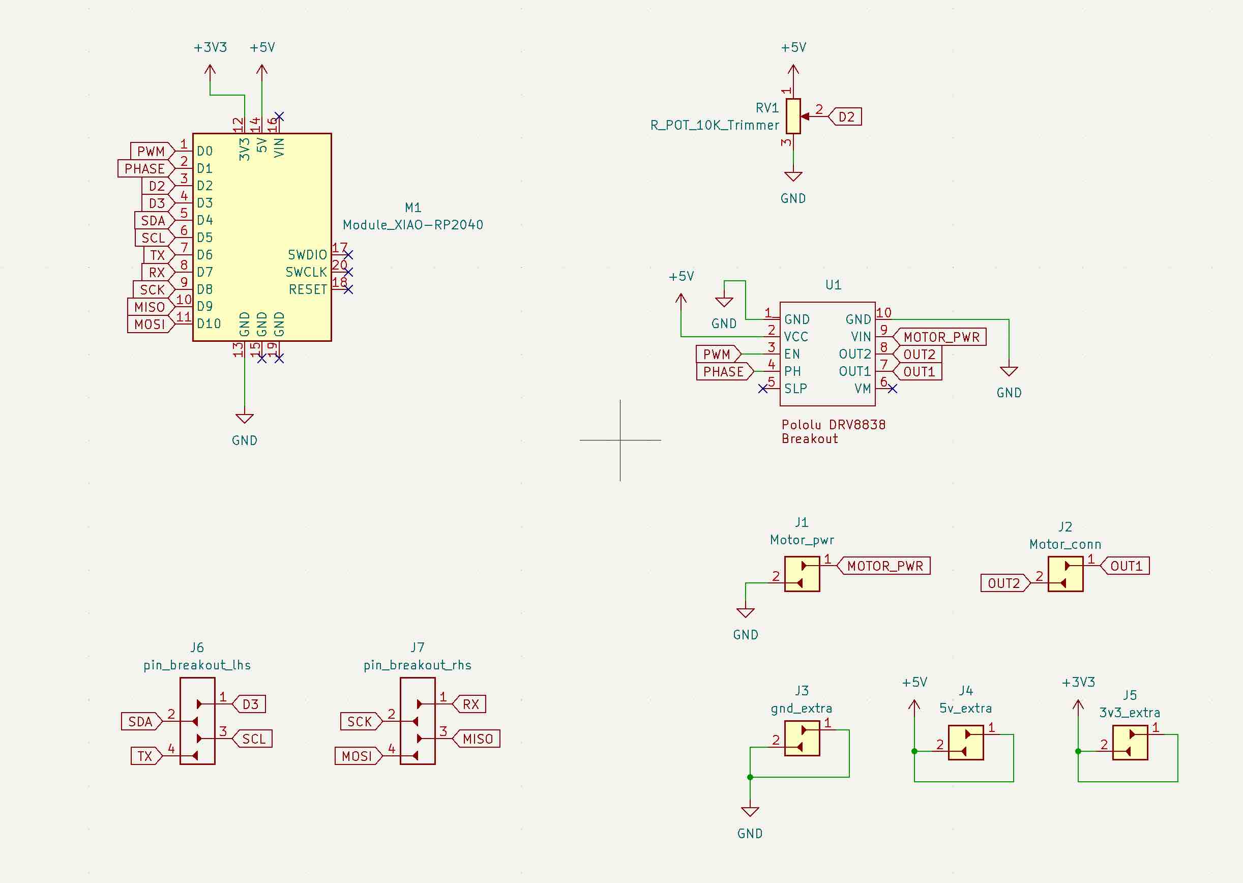 Final schematic in KiCad using the custom symbol created earlier. I found it helpful to work with the global-label tool
(
Final schematic in KiCad using the custom symbol created earlier. I found it helpful to work with the global-label tool
( Cmd + L ) to keep things clean and ledgible.
"Ratsnest" to start with ... connected components, with updated footprint for the Xiao.
I wanted to included some fixation points (e.g. for M3 screws), so drew a a board outline in Onshape, which I was able to import as a .dxf
onto the edge_cuts layer via File > Import > Graphics .
Initially, I routed all my tracks at 0.25 mm, but looking at previous example boards wanted to increase these to 0.5 mm.
Hovering over a track segment, pressing U (select whole track) and then E (edit), allowed me
to change the thickness of a single track. Holding down shift, I was able to select all the tracks and do a single edit,
though I'm sure there must be a more elegant way to do this for more complex designs?
Checking everything looks correct using the 3D viewer; the exported .svg of the F_Cu layer (traces)
and edge-cuts (i.e. board outline).
I found the process of exporting the .png quite helpful as a design check - the black and white contrast making it more obvious
where traces were closer than they needed to be and also revealing some small loose traces I hadn't seen in the edit view.
As a general resource, I found Zach Fredin's video recitation from HTMAA 2020 very helpful in giving an overview of the KiCad design workflow.
---
Group ~
In the Architecture shop, we ran through some test equipment: using a multimeter to measure the input voltage of the Xiao,
testing some loose resistors, the voltage of some batteries. We also took a look at the oscilloscope: trying to zoom in on some Serial
data packets being sent to Danny's display and receiving waves from the function generator.
Testing test equipment
Files: First_board-F_Cu.svg