Week 10 ~ networking
Transmit and Receive
For my final project, I would like to send wireless commands to the individual surface modules.
I think it makes sense to have one 'controller' module that could be hooked up by USB/serial to my laptop, and send wireless instructions to the other 'peripheral' modules. The Xiao RP2040 does not have wifi/bluetooth functionality built in, so I will be using the
NRF24L01 wireless transceiver (slightly confusingly, they operate at 2.4 GHz - but don't allow for Wifi functionality).
To attach the NRF24L01, I redesigned the motor driver board I had previously designed. In particular, I had to reshuffle the pin assignmented as it seems SPI (serial peripheral interface) pins are designated to particular pins on the RP2040 and I had previously used these for the LED and button.
I was surprised actually by the amount of pins required (PICO/POCI/CE/CSN/SCK/GND+VCC). As a result, routing the traces proved more difficult and I added thru-holes in a few places to allow jumper wires to bridge traces I couldn't complete.
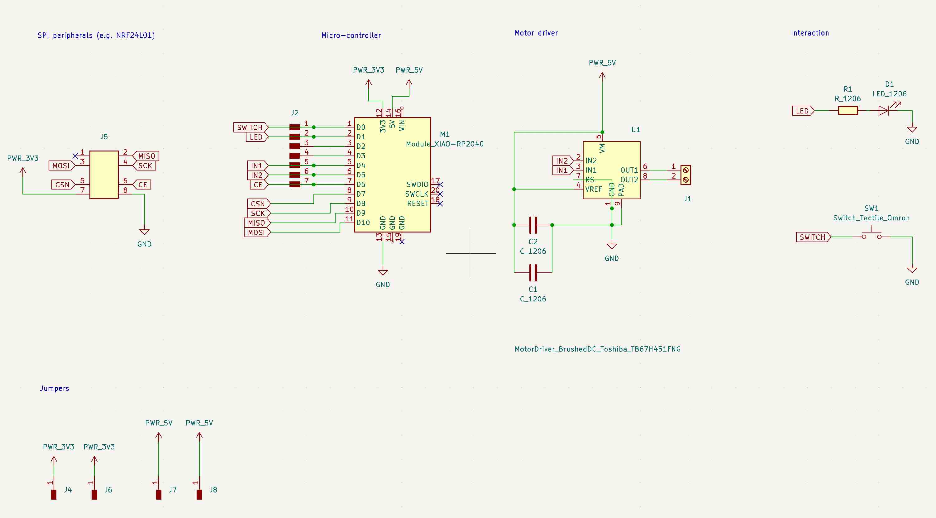 Schematic; figuring out the traces for the redesigned board; adding thru-holes to
bridge unconnected parts of the ratsnest on the 3.3V and 5V lines.
Updated traces, thru-holes (to allow for jumpers on the 3.3V and 5V lines) and edge-cuts.
Milling the board on the MDX-20 for a change; back of the board with jumpers.
Schematic; figuring out the traces for the redesigned board; adding thru-holes to
bridge unconnected parts of the ratsnest on the 3.3V and 5V lines.
Updated traces, thru-holes (to allow for jumpers on the 3.3V and 5V lines) and edge-cuts.
Milling the board on the MDX-20 for a change; back of the board with jumpers.
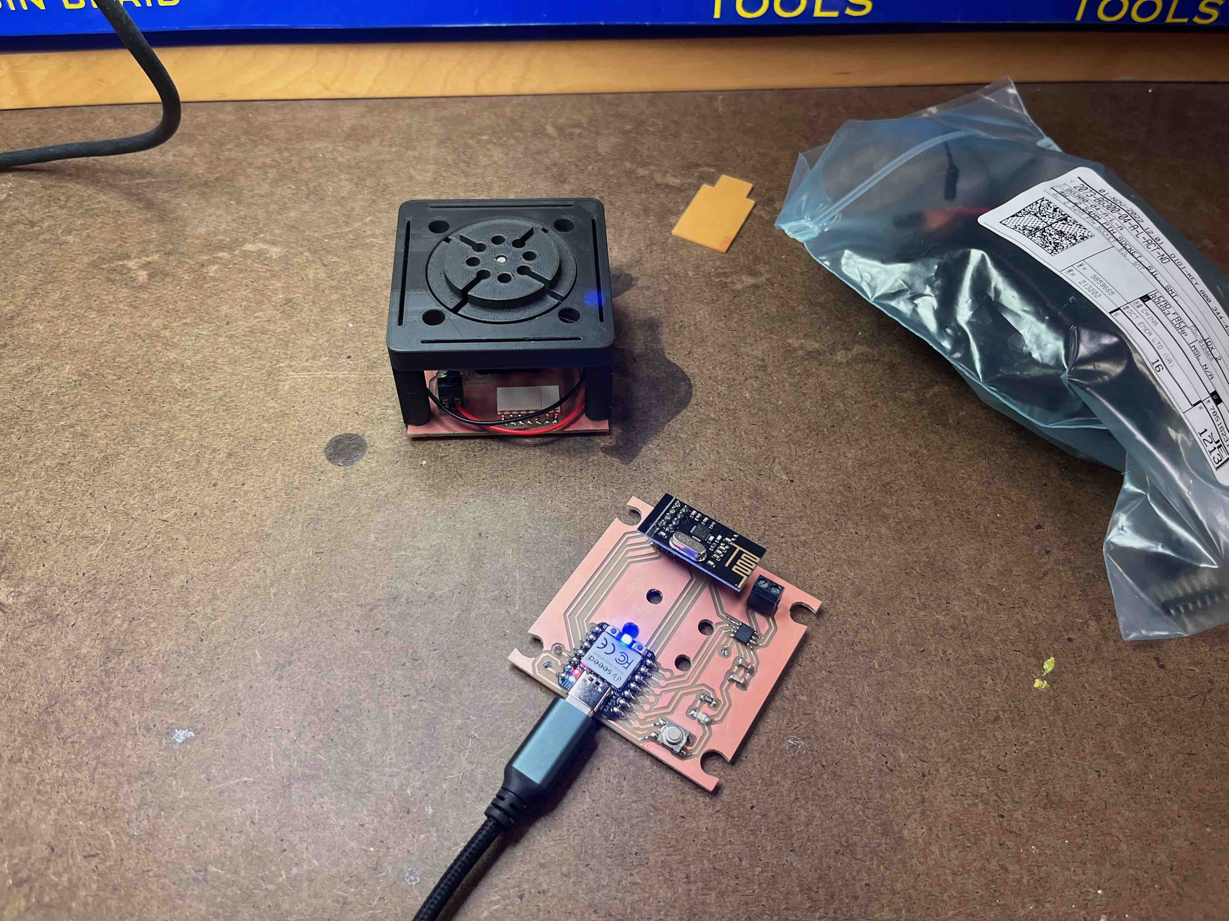 Assembled board with NRF24L01 chip next to earlier module prototype. I think I'm quite happy with the design; the motor will be mounted in the centre.
Transmitter code:
Assembled board with NRF24L01 chip next to earlier module prototype. I think I'm quite happy with the design; the motor will be mounted in the centre.
Transmitter code:
// Niklas Hagemann
// HTMAA 2023
// Transmitter code
// adapted from: https://lastminuteengineers.com/nrf24l01-arduino-wireless-communication/

//Include Libraries
#include
#include
#include

//create an RF24 object
RF24 radio(D6, D7);  // CE, CSN

#define button_pin D0
#define led_pin D1


//address through which two modules communicate.
const byte address[6] = "00001";
int button_index;

void setup()
{

  Serial.begin(9600);

  pinMode(led_pin, OUTPUT);
  pinMode(button_pin, INPUT_PULLUP);
  radio.begin();

  //set the address
  radio.openWritingPipe(address);

  // Set module as transmitter
  radio.stopListening();
}
void loop()
{

  // check if data has been sent from the computer:
  if (Serial.available() > 0) {
    // read the most recent byte (which will be from 0 to 255):
    button_index = Serial.read();
    Serial.print("button press: ");
    Serial.println(button_index);

    Serial.println("hello ... testing ");

  digitalWrite(led_pin, HIGH);
  //Send message to receiver
  const char text[] = "Hello World";
  radio.write(&text, sizeof(text));
  delay(1000);
  }
  else {
    digitalWrite(led_pin, LOW);
    delay(50);
  }
}
Receiver code:
// HTMAA 2023
// Niklas Hagemann
// Receiver code
// adapted from: https://lastminuteengineers.com/nrf24l01-arduino-wireless-communication/

//Include Libraries
#include
#include
#include

//create an RF24 object
RF24 radio(D6, D7);  // CE, CSN
const int led_pin = D1;

//address through which two modules communicate.
const byte address[6] = "00001";

void setup()
{

  pinMode(led_pin, OUTPUT);
  while (!Serial);
    Serial.begin(9600);

  radio.begin();

  //set the address
  radio.openReadingPipe(0, address);

  //Set module as receiver
  radio.startListening();
}

void loop()
{
  //Read the data if available in buffer
  if (radio.available())
  {
    char text[32] = {0};
    radio.read(&text, sizeof(text));
    Serial.println(text);

    // blink the LED if we are receiving data
    digitalWrite(led_pin,HIGH);
    delay(200);
    digitalWrite(led_pin,LOW);
    delay(200);
  }
  else {
    // don't blink
    digitalWrite(led_pin, LOW);
  }
}
Plugging in the 'transmitter', triggers the LED in the 'receiver' ...
In the end, it all worked quite well (video above: the transmitter sends a message to the receiver at the address 00001; upon hearing the message, the receiver blinks the LED).
Now I just need to integrate the above with the code to drive the motors.
Final project update: control two motor modules (module 1 acting as transmitter, module 2 as receiver - see Arduino code files below).
Also see interface week.
Files: traces.png, holes.png,
edge_cuts.png, receiver_motor.ino,
transmitter_motor.ino