
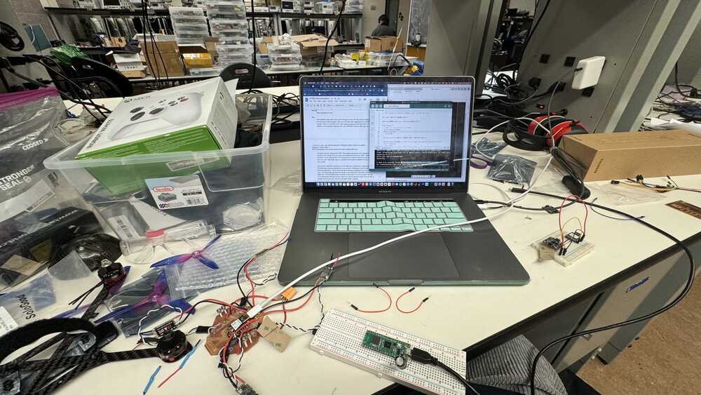
Final Project - Drone
I ran out of time to take pretty pictures before I left for the semester D:
...I will take them when I come back after IAP and will update future progress on my drone!
What does it do?
My drone reads data from an IMU and controls 4 motors to spin.
Who's done what beforehand?
The main source of inspiration comes from Daniele Ingrassia who made a drone in 2015 for FabAcademy. Throughout the class, I have also been fascinated by Yusuke Takahashi's flapping tail fin flyer. They are so cool but both projects are way out of my skill range and from speaking with the TAs I could learn more with a drone as there will be more stages I can achieve compared to an orthnitoper. I did not have much experience with electronics or coding at all before taking the class so this project was a crazy one...
What did you design?
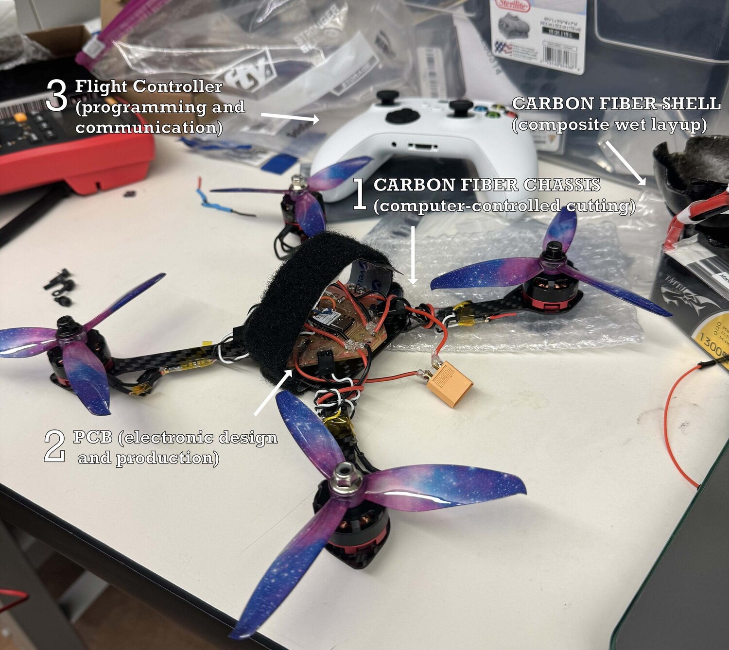
Chassis, PCB, and flight control
Materials, source, cost
- Seeed Studio XIAO ESP32C3 - $5
- 2300KV Brushless Motor CW/CCW 3-4S - $37
- 4Pcs 20A ESC Brushless Electronic Speed Controller DSHOT BLHeli_S 2-4S Lipo for FPV QAV Drone Multirotor Quadcopter - $31
- LiPo Battery Pack 1300mAh 45C 3S 11.1V with XT60 Plug - $21
- Adafruit 9-DOF Orientation IMU Fusion Breakout - BNO085 - $25
- Carbon Fiber Fabric Plain Weave (for chassis shell provided during composite week) - $20ish?
- Lightweight Carbon Fiber Sheet - $30ish
- 8Pcs 3-Blade Propellers 5 Inch Props - $16
- Copper boards for PCB - found in class inventory - $1
What parts and systems were made?
What processes were used?
- 2D and 3D parametric design
- Additive and subtractive fabrication processes (FDM, SLA, SLS 3d printing, and CNCing)
- Carbon fiber wet layup
- Electronics design and production
- Embedded microcontroller design, interfacing, and programming
- System integration and packaging
What questions were answered?
- How do I design and produce electronics and integrate them into my manufactured parts?
- How can I make sure my chassis will be able to withstand the thrust output?
- How should I go about programming the flight control?
- What is the best way to 3d print 3 ring toroidal propellers?
- How do you generatively design a drone?
- How can I make a power distribution system for my 11.1V 3S battery to power all the ESCs and my microcontroller that takes in lower voltage?
What worked? What didn't?
Parametric design worked well, electronics design and production worked decently well. I spent too much time on the toroidal propellers and generative design. Embedded programing (flight control) got too complicated.
How was it evaluated?
My project is evaluated on the level of effort put in over a super busy semester with two final projects due the week before and two finals sandwiching the final presentation of how to make.
What are the implications?
I can make (ALMOST) anything after taking the class! I never thought I could make a drone (or at least look like a drone) in just 4 weeks. If I had more time to spend on flight control programming (which is mostly done just the debugging got too complicated), I would have a functioning drone. I plan to finish this after the class ends. Neil's ending talk really resonated with me: how the last day of class is when the class starts. As an undergrad, it was very difficult to manage this class along with my 4 other classes and my extracurriculars. Last month of school was basically h*ll for me. It was a fever dream. But I managed to get everything done. I did debate this months ago what if I should drop something so I can have more time for each thing. The problem is, I already dropped 4 things after getting into the class and my final schedule is what I ended with. I wanted to give nothing else up. I had a really bad day where I missed a lot of scheduled things because my body just crashed and overslept. But since then, I have been able to appreciate myself more by reflecting on the amount work I was able to get done this semester. While my drone did not fly, I have learned the skills to make it fly. I learned that if I set my mind to do something, I will be able to do it. If I want to make something, I will be able to make it. No matter what (almost).
Final week schedule...
- Wednesday (12/13): Figure out how to make arm DONE
- Thursday: Busy...
- Friday: Find Alfonso to figure out how to connect all my drone components DONE
- Saturday: Find Anthony for PCB help and finish drone chassis DONE
- Sunday: Finalize electronics, print PCB, and connect electronics DONE
- Monday: Take a final in the morning. Afterwards, integrate and do flight stabilization code... tried my best
- Tuesday: Finish whatever and present... DONE!!!
- Wednesday: Take another final, take a train home, and finish documentation on train and at home and pray Neil goes in alphabetical order so that I'm last and I can finish in time. Also SO SORRY ABOUT MY SCREWS FLYING OFF. I'm still deeply reflecting the moment and how my life flashed before my eyes. Really thankful that no one got hurt.
Initial Calculations
Propellers
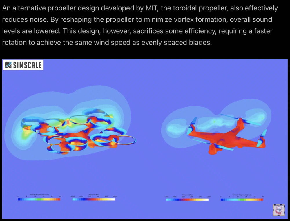
Choosing the right propeller is important. First I pick a 5in diameter propeller for my chassis to be 210 mm in diameter. As I researched different propellers, I went down a deep rabbit hole on the battle between MIT toroidal and Zipline propellers. Overall, some sources are saying the zip line version works better (less noise) and does not sacrifice efficiency like the zip line version so i will try both
-
Some references and comparisons between the two propellers.
- MIT Toroidal Propeller
- How Do Zipline's Silent Propellers Work?
- Recreating Zipline propellers
- Recreating Toroidal Propellers
- Comparing the Two Propellers
- StrikingFPV's Tri-loop Toroidal Propeller
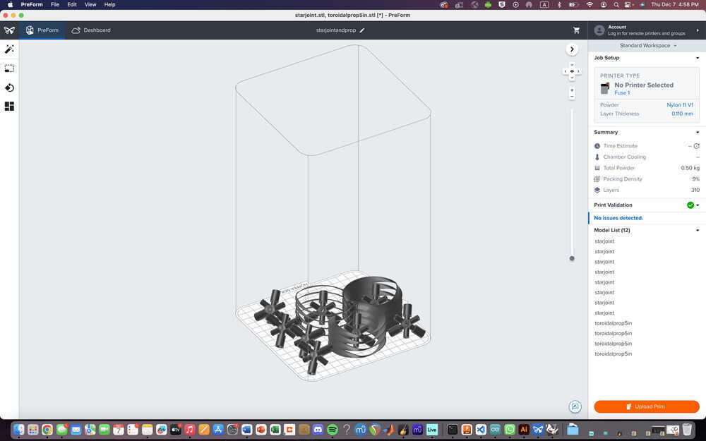
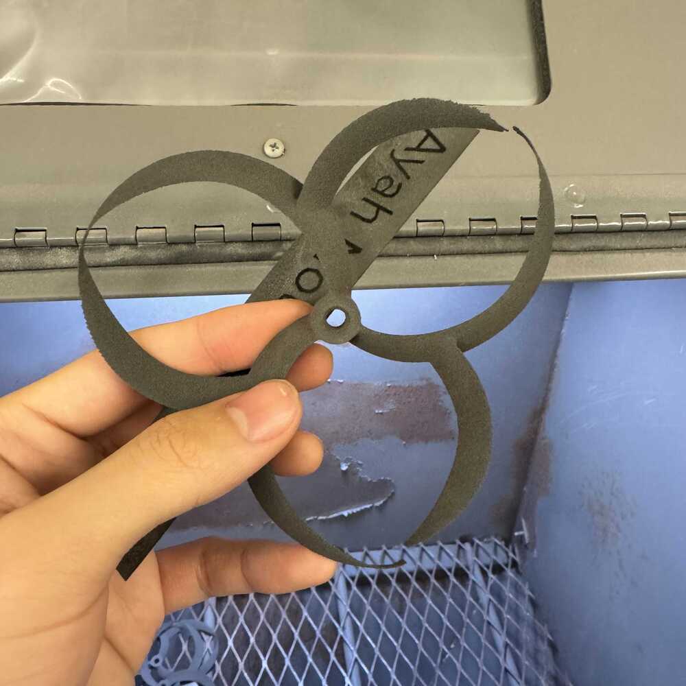
OK after a lot of thinking I’m going to go with the V3_Tri_Loop_5-inch from Striking FPV’s Thingiverse. The Zipline one seems nice but tests on models online don't show promising results because people missed details recreating the propeller. On the other hand, there have a been a lot of test on the StrikingFPV tri-loop and the creator itself has uploaded many improvement updates, and it seems pretty nice. None of them actually used a nylon/carbon fiber mix so I’m excited to try that out! Also the inside is 5.2mm in the design sko I downloaded the fusion file and changed it to 5mm to fit my motor. I also added the material: Nylon 12 (with Formlabs Fuse 1 3D Printer) so I can get an approximate weight for the propeller. The weight of this comes out to 3.221 g and is actually lighter than the iFlight F5 that was used in the detailed testing video. All the props were printed on SLA printer in the testing video.
Printed a PLA model to see it
Feedback from Class
Someone recommended that I actually print the propellers on a resin printer instead of the nylon one.
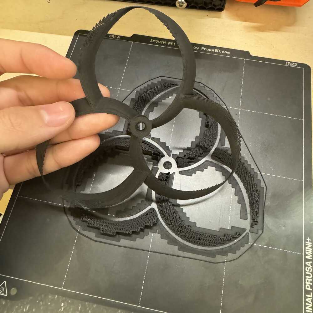
Testing a Nylon 12 SLS printed version
I was already printing on SLS for another class and I was easily able to fit my props on there so I did. I just wanted to see how it works/feels like.
So the sides were too weak and the recommendation was right
Update on the 5mm press fit hole: after doing more CAD and designing for press fit for my chassis, I learned that its good to adjust for hole when 3d printing. I think the 5.2mm was intentional to allow for some space so for my next iteration I will use this.
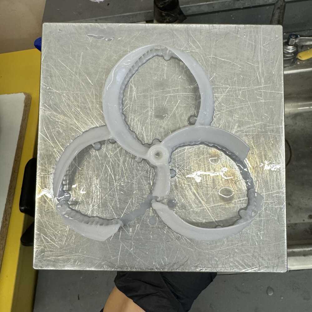
Resin version on tough 1500 resin.

First attempt failed and SO MANY parts ended up in the tank it was so sad for Bill to clean it out and he couldn't get all of it so it needs to be filtered now (he cleaned it up before I got back so I could not see it for myself but the story was really sad :( )). The first nylon one was slightly tilted, with support touchpoint size at 0.5mm(default). The second one works with fully flat layout (such that the propeller would print radially outwards) and 0.7mm touchpoint size. Second attempt worked but there were some deformation when I took the supports off the props. I will have to test these but since I'm low on time (Dec 15) I will order some legit ones and get them Monday in case the toroidal things don't work out. The comparision video did mention how these props are difficult to manufacture right now because they are so new. The shop managers at the Morningside Academy for Design were super nice and Bill opened a new box of Rigid 10k resin for me to test. This will be the last ones I try to 3D print.
Resin version on rigid 10k resin.
These props did not print well. Like the first attempt of the tough 1500, maybe the supports weren't strong enough and we're not sure exactly why. This is Saturday so I'm the one trying to clean it up and maybe restart because the 1/2 of the propeller that I do have looks really promising. This one failed unforunately (not as bad as the tough first attempt) but there is one piece stuck to the bottom of the tank that I can not gently take out so I cannot run another print with different settings. Bill thinks the problem is mainly cause we choose thinner 0.05mm layers (compared to 0.1mm layer for the successful tough) which increases the likelihood to fail. We also used a 0.6mm touchpoint size. We're not pros at the Formlabs Form 3 printers so we were just trying our best and not exactly sure if any setting would be perfect but lesson learned here is don't fix if it ain't broke... Nonetheless, I think these would have worked if I had more time. The rigid 10k seemed really promising.
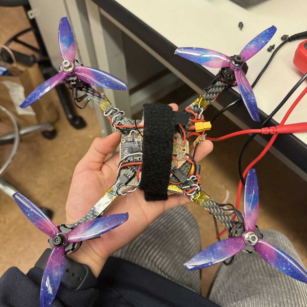
Actual legit injection molded props
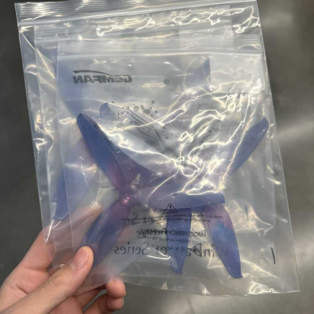
Good thing I ordered these Friday and arrived Monday (starry is the only color that would arrive on time, all the other ones would arrive Tuesday). Sad that the toroidal didn't work but at least I have some propellers now.
Chassis
New Inspiration: The Helyx Drone
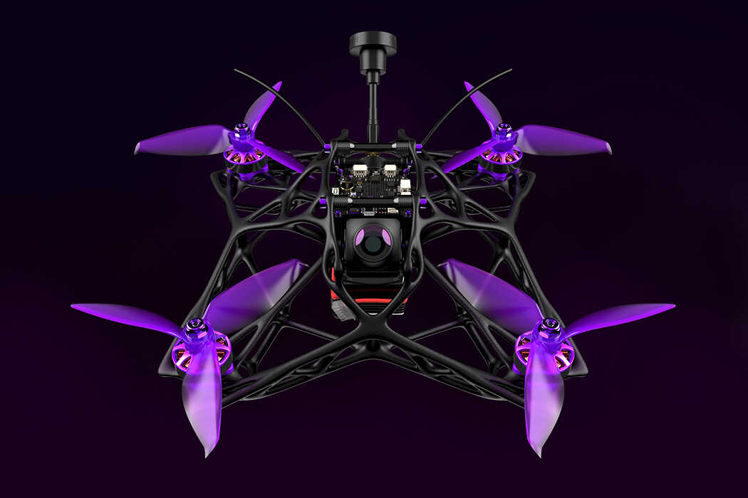
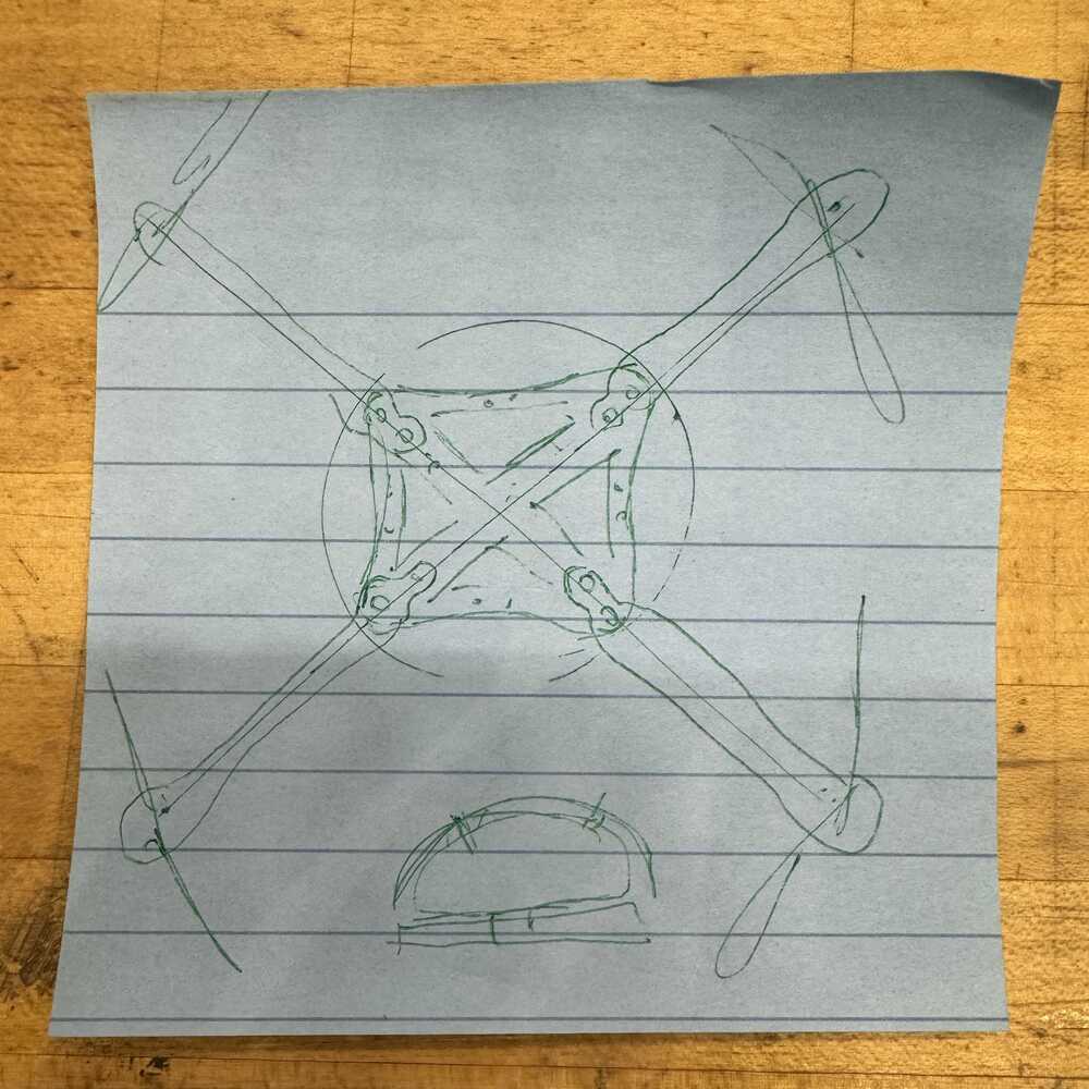
I really like the generatively designed Helyx Drone. With my new insights on generative design, I attempt to recreate a chassis with generative design using Helyx as an inspiration. In my original sketch, I had the battery in the middle of the drone and electronics around it but I soon realize that this arrangement is not ideal. Having the battery under it would allow me to place all of my electronics together and should help with the center of mass in a way.
Constraints used by Helyx

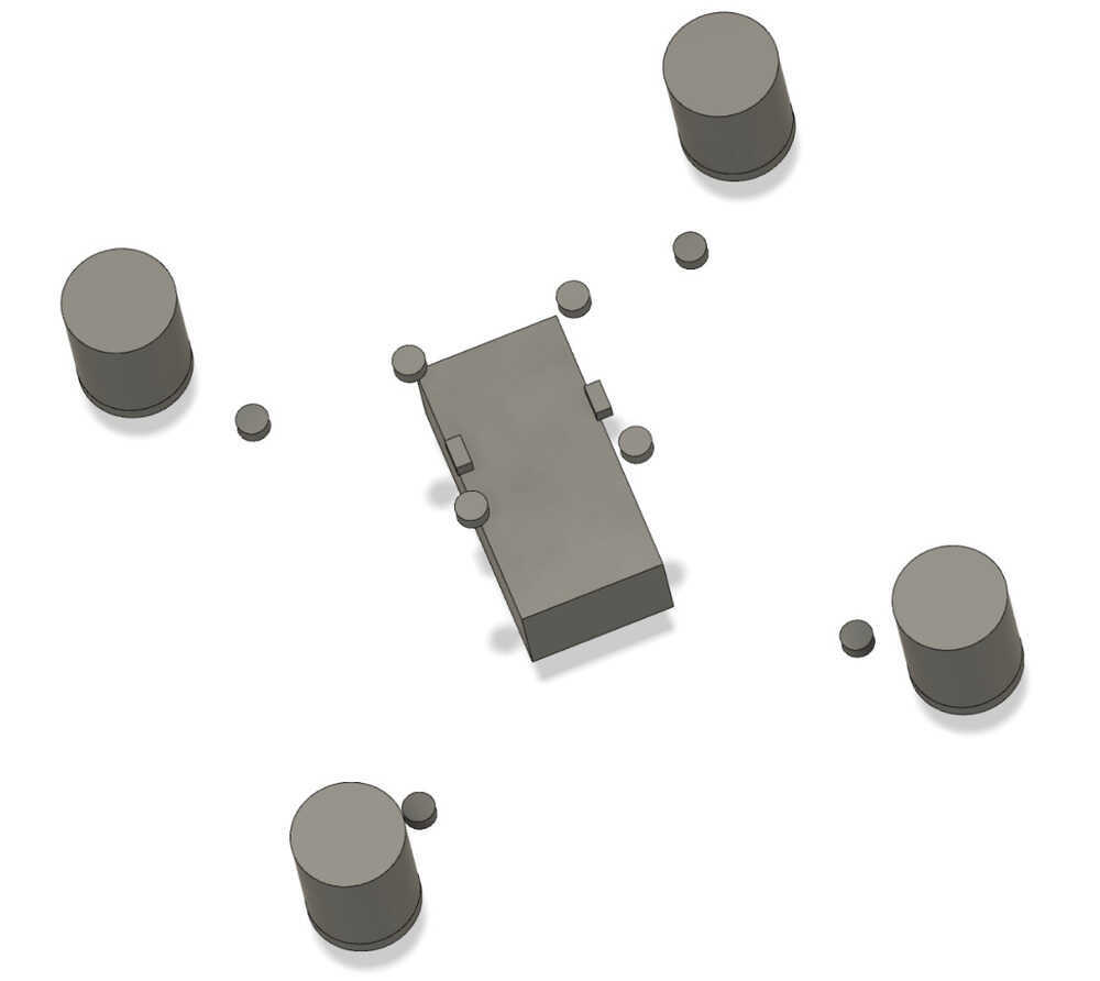
With these ideas and my previous practice, I attempt generative design again. Throughout the machine week a learned a lot about components and integrating different designs together. With my PCB designed. I import it to my chassis. I make a shape for battery. and I make a shape to hold my PCB.
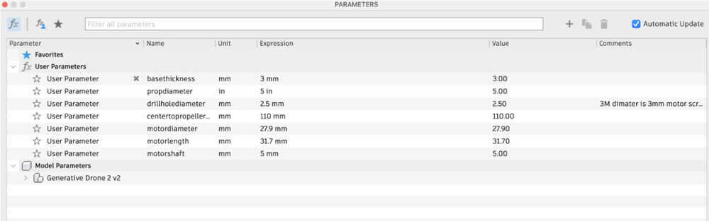
No clue where this is going but my parametric design looks slay
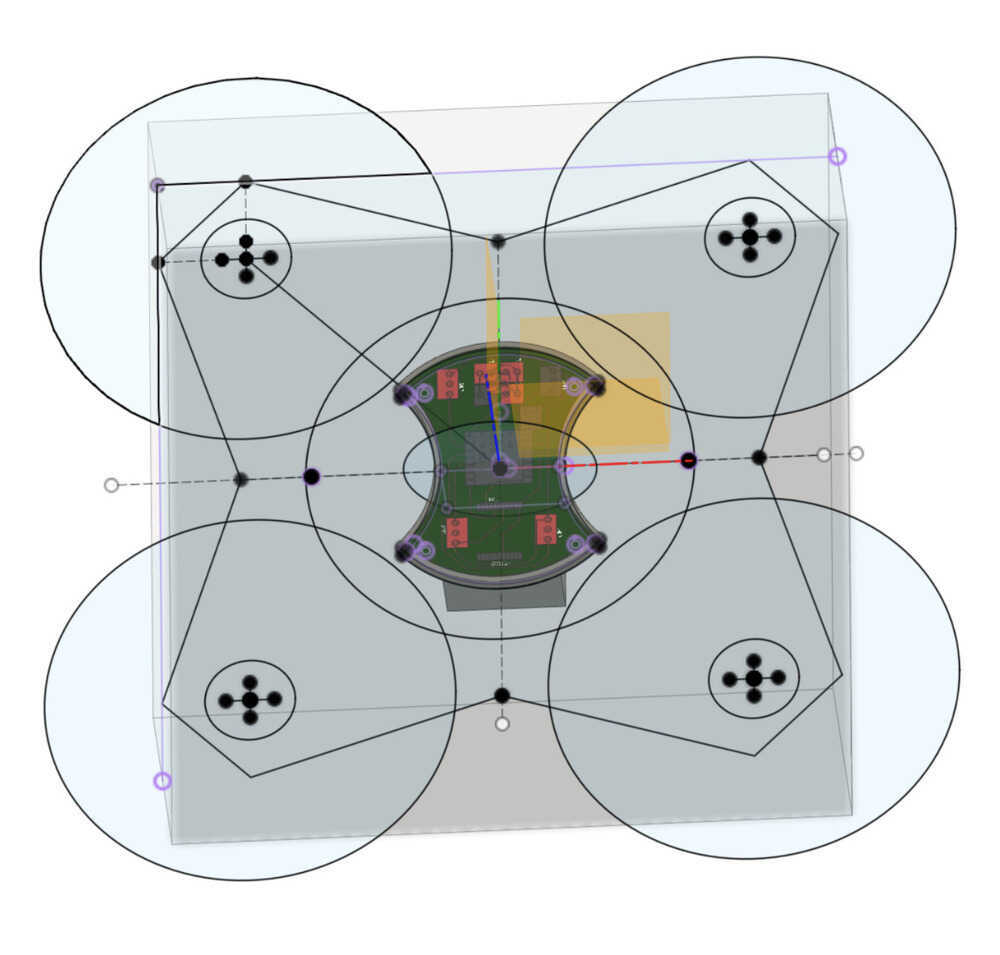
I have to consider how I would add the screws. A lot of sources recommend 3.2mm for M3 screws so I'll do that.

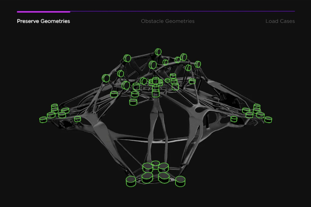
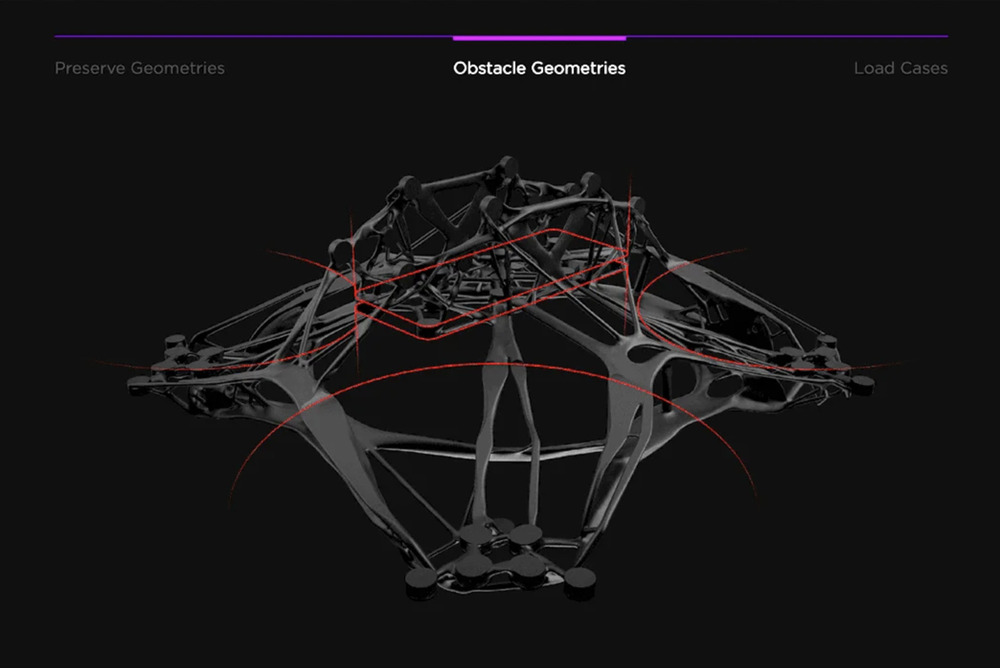
The original idea was to have the screw hole as obstacle geometries but looking at how Helyx did it. I realized it might be a better idea to leave them as preserve geometries and then cut the holes out later so there is material around the holes! So for the 3.2mm holes I made them 8mm
Here are the loads. I got these numbers from my thrust calculation sheet on top of the page.

Converged Design :o
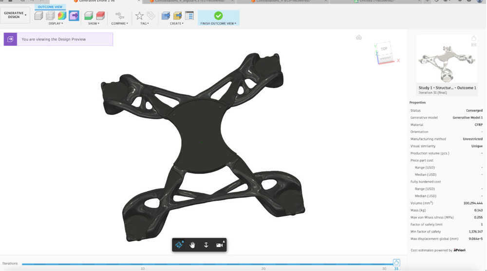
Wait this looks cool, im think i want to add more preserve geometries just to guide it places
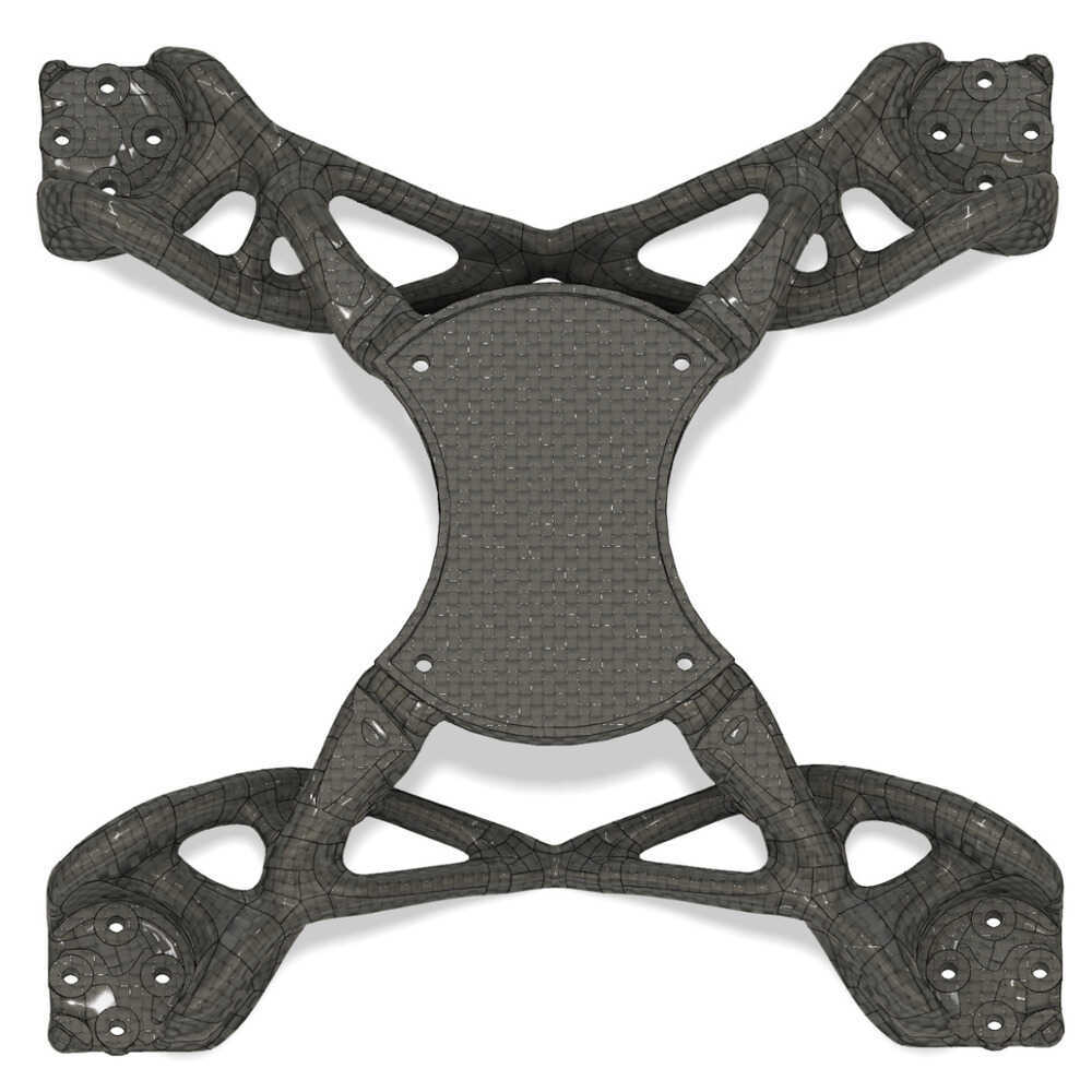
While the new one is generating, I exported the best one from the first best to test and its so niceee. I’d be happy just making this if the new one doesnt turn out

Cut the holes manually and it worked pretty well. The preserve geometries came out planar and I was able to easily edit it.
I try printing this design on the Bambu using PETG but I was experiencing some issues and couldn't get the print in time before meeting with Alfonso for composite week. But I will show him the design.
Notes from composite discussion
So my cool organic thing is too hard to make with wet layup because its too complex. Wet layup is good for making shells. For going around things...
Based on this meeting I made a lot more simpler design.
Check out Wildcard Week where I work with composites to make a sphere shell for my drone chassis.
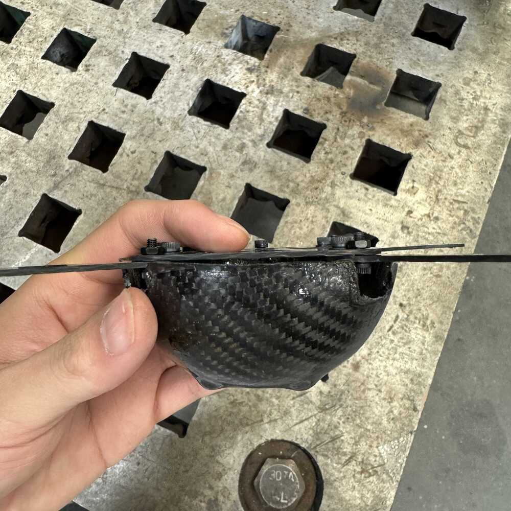
Carbon Fiber Drone Shell
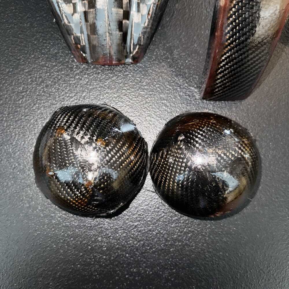
Here is the final ball I made from composite week.
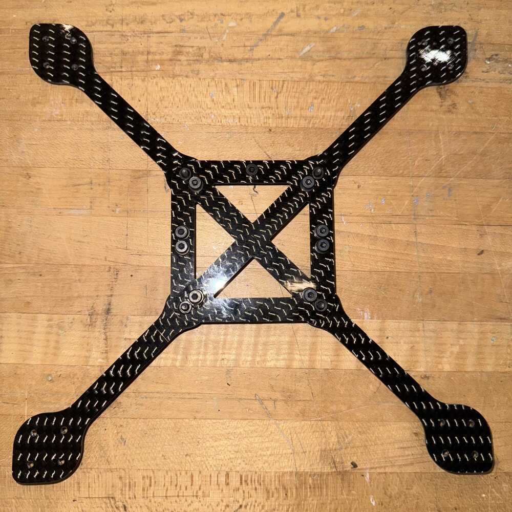
Inside skeleton and arms
To connect my hemispheres and arms, I design a bracket that goes on the inside. Alfonso helped me brainstorm ideas.
The X bracket will be where most of the load will be applied and the screws on the sides are for velcro to connect the top and bottom shells.
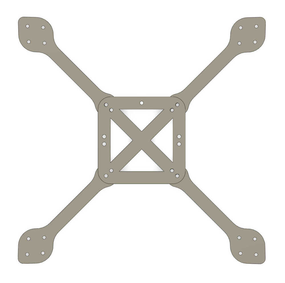
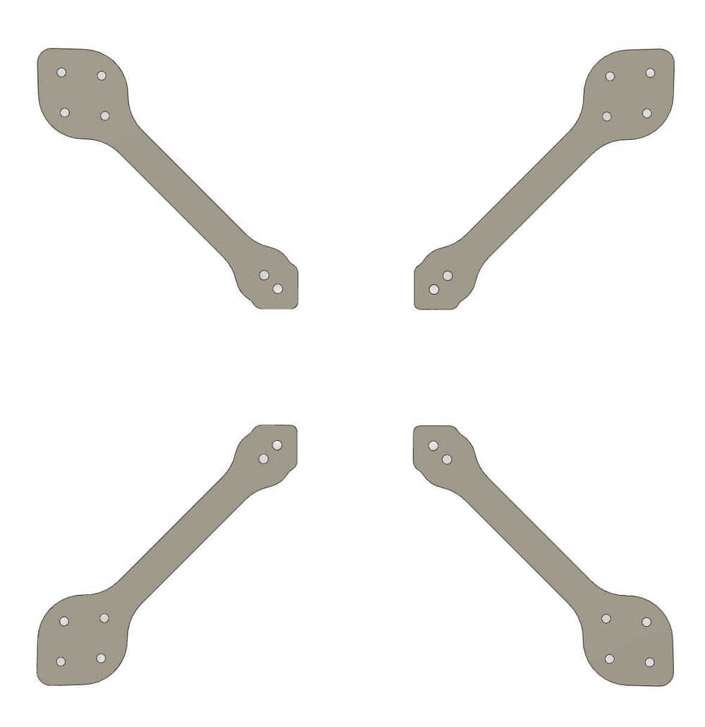

I sent these as DXF to a service and got them cut wooo thickness is 1.65mm.
Parts arrived and here is my assembled chassis!

I will find velcro and add it to my shell and chassis.
PCB
Power Distribution
I have to design a place for power to plug in and distribute to the other parts of my system. 4 are for the ESCs and one is for the ESP32-C3 which needs a voltage regulator from 11.1V to 3.3V.Here is a circuit of a voltage regulator we have in the inventory: AZ1111I-AD from its datasheet. I found two diagrams and I'm unsure which one to use. The circuit I want to get is 11V in and 3.3V out which is a feature of both of the diagrams.
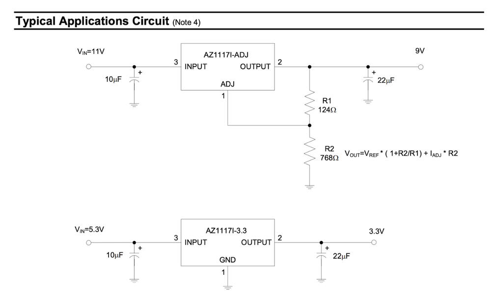
I found Anthony the next day and learned that I can just use the bottom one because the voltage regulator can intake whatever voltage it allows and output always 3.3V. The top diagram is to show that if you want to output something other than 3.3V then you have to add resistors. Ok this makes my life easy. I understand how to use the voltage regulator now.
Here is how I can send the power to my ESP32-C3.
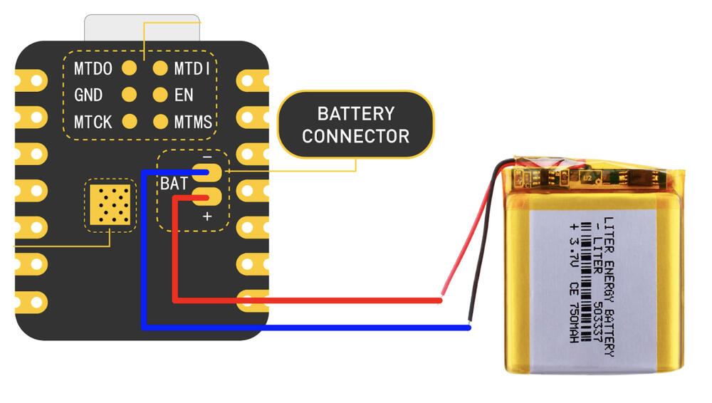
With these new parts of my PCB figured out, I added with my previous schematics for IMU (input week) and ESC motor control (output week) to create a final PCB schematic for my drone.
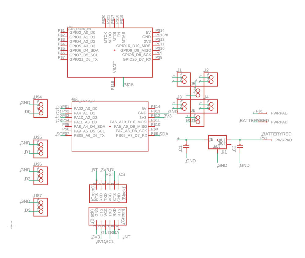
After spending quite some time on my final PCB, I ran into an issue where I theres no connector for the backside battery connector on the electronic ESP32-C3 component. I tried some ways to work around it but none seem to work. I can’t manually route anything to the battery connector. It appears in the PCB view but not in the schematic view. I try to overlay 1 pin connectors overthem but it doesnt work. I found another ESP32-C3 component that does have the battery connector but its only the positive (P$16). I can’t get the negative (P$15).
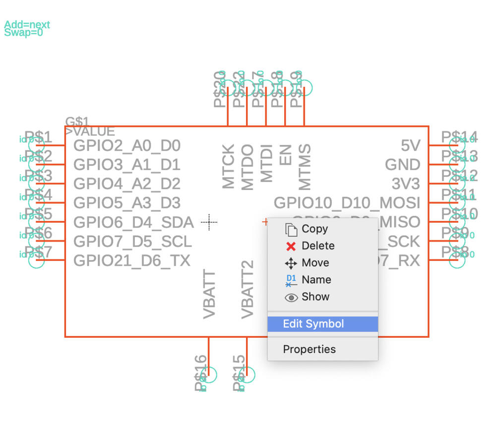
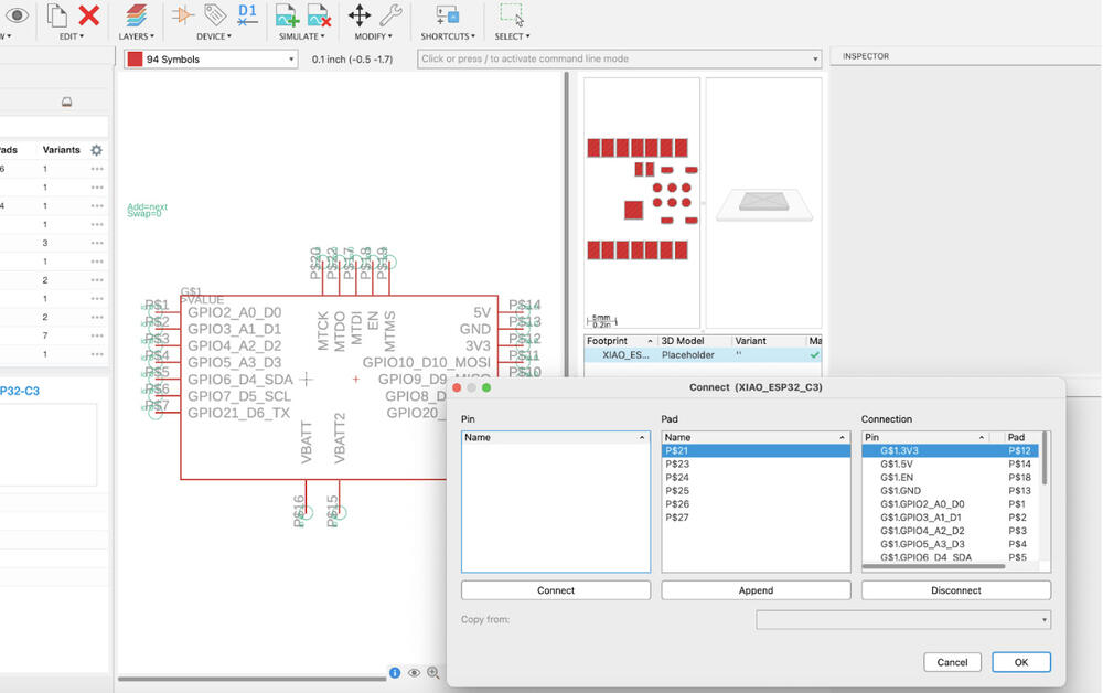
Ok I figured it out. Right click the component I want to edit. And edit the library. Once you see the component in the new library editing page, right click it to edit symbol (pic 1) and then I added one for GND. I could not figure out how to go back to the previous layout to connect it (stuck in the adding symbol layout) so I just reopened and I was able to connect the pins (pic 2). For some reason GND had already P$15 and 7 other pins connected to it so I disconnected them and connected VBATTGND to P$15.
Actually, after I spent all that time figuring out how to edit the component, I found out that don’t need to do that. I found out that I can input power via the 5V pin just put a diode to make sure the current flows only one way from my battery to the ESP (anode to cathode) and also the GND of the battery connector is connected to the GND on the front so I dont even need to use the back.
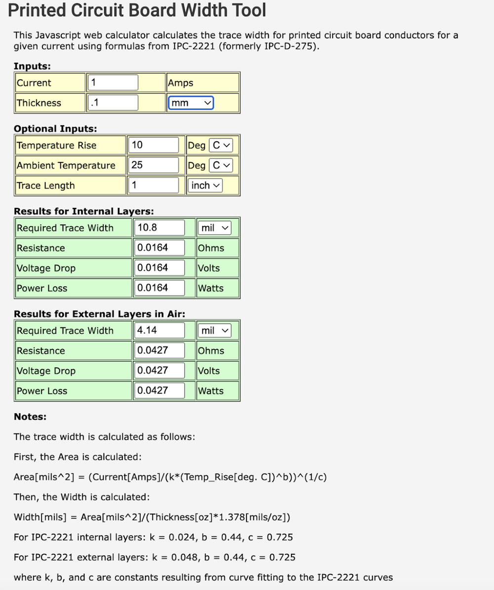
I also checked for trace width size I need to carry my power and seems like 16 mil is good enough.
Final PCB?
Nope... just found out from a friend that was doing the the battery connection via the 5V that it doesn't work. So I'm editting my PCB board.
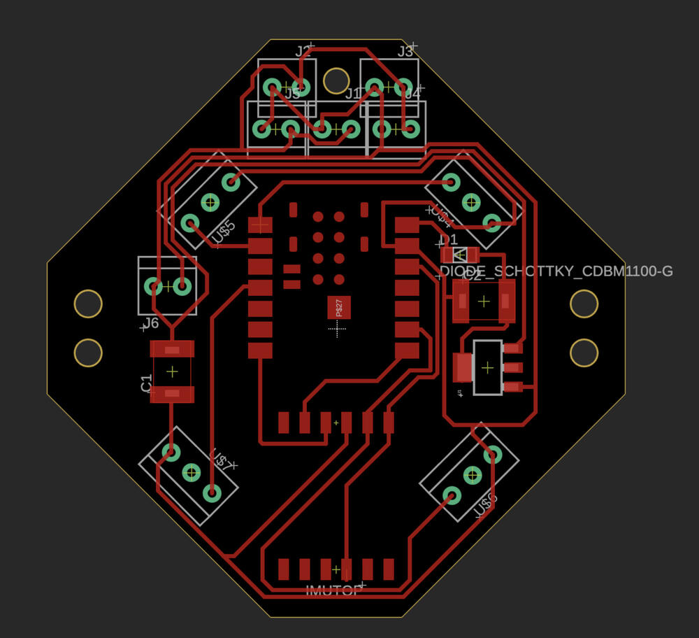
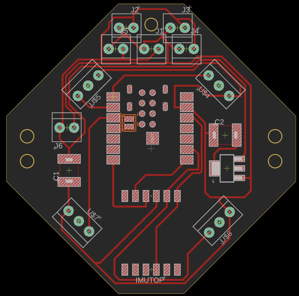
Final PCB!
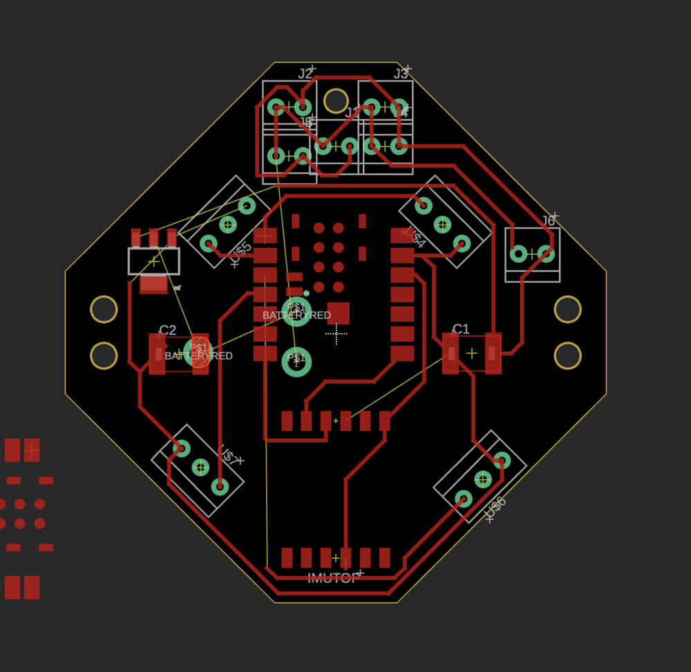
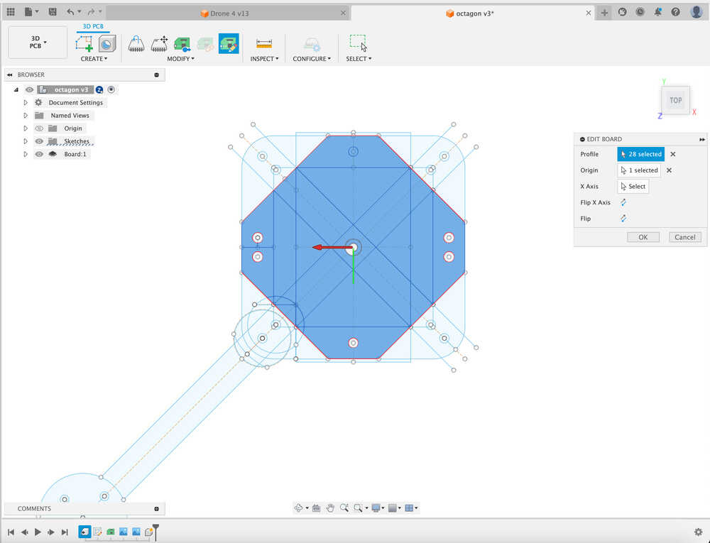
I’m cutting a hole through the back to connect it now. Combining all the components I did throughout the weeks, here is my final PCB design with ESP32-C3, BNO085, 4 ESCs, and a power distribution. The board shape is linked to the shape I have given for my PCB on my chassis design. The length is just the length of my battery and I'm glad I learned about components, and linking things through my CADs this semester (it really helps with design, parametric design, and integration nicely).

Fabricating PCB and soldering electronics
All the 1/64 endmills are bad so I had to seek help to get some endmills. Found them in the shop later tonight (thank you to anonymouse legend who read my issue replaced them!)

I think this my best PCB yet! Wooo! This is my second try for this PCB. The first one cut just as well for the traces but unluckily, the board lifted after cutting the outline since the program decided to cut the outside line first before cutting the inside holes. I thought about maybe programming this to cut the inside holes first but I just put more tape and it worked. I gently polished my beautiful board with just Gojo soap and handwashed it.
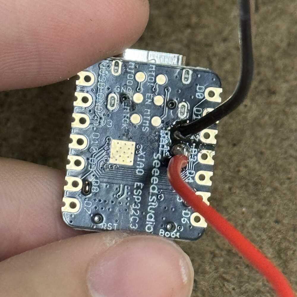
Here is my soldered on back battery connectors
Oh no the solder for my power distribution intake broke. I used too heavy and short wires that went upwards. I try to replace them with these smaller ones but I'm having a hard time fixing it. Oh no. I run to the EECS shop from the Arhshop for help (bringing all my stuff).

I set up station as I plan to stay here the WHOLE night... I managed to fix my PCB, I learned that I can place the wire any where along the trace (preferably the biggest spots). AND DUMP HOT GLUE ON IT TO SECURE IT. I did just that. Here is my board with the power in from outside connected and power into the XIAO connected.
I'm a bit wworried that my connections aren't good, and I want to make sure EVERYTHING works before I connect a battery because batteries are scary. For this, I learned how to use a DC power supply to link to my XT60 connector and check for continuity in all the parts of the power distribution. To my surprise, everything works!! All the 4 power and ground for the ESCs work and show 11V just like the input and the connection for the ESP shows 3.3 so my voltage regulator is also working! Oh also instead of using 22uF for the 2nd capacitor I used another 10uF as recommended by Anthony (cause where do I even find a 22uF capacitor)?
Here is my PCB board with the ESCs connected to its 3 pin (data and gnd so 2 pin actually the middle one isnt used) and power distribution on top. My board is really growing!! Learning from my mistakes... you can see how much hot glue I have used to secure everything. From this experiement, I have definitely learned little tricks when designing PCBs to make sure that my connections are nice but also learned that hot glue just comes in soooo handy.
P.S. I really like the aesthetics of this board yay.
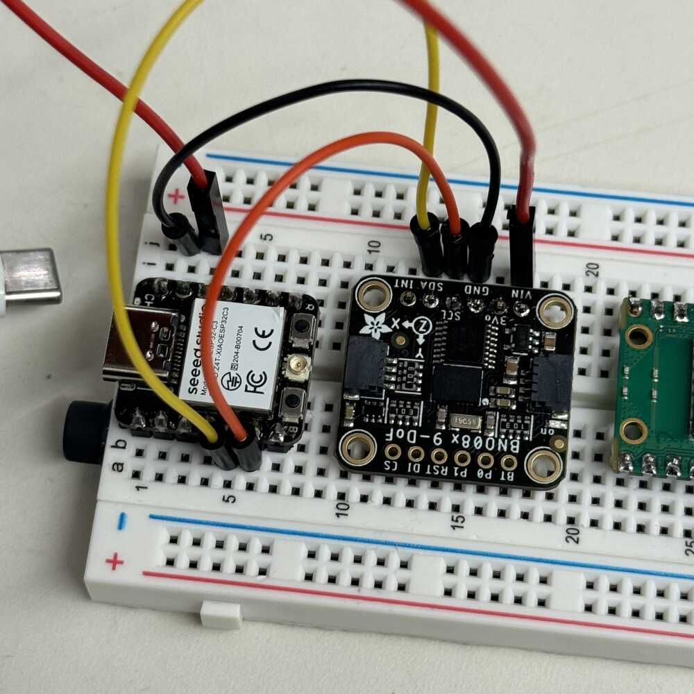
Ok 2 weird problems: (1) my ESP lights up when I power it with USB but not when I power it with the power supply, (2) my IMU isn't lighting up when I power it. With Anthony, we figured out that the LED on the ESP32-C3 is powered by 5 volts so because my power in is 5v, it just won't light up anymore but it still works just powered through its back battery connector! Unforunately, the IMU is a bit unlucky, I tested all the connections and it seems fine but I just can't figure out why its not working. Maybe I fried it somehow. So I ran across main campus at 12AM to find another IMU. Was able to find one 30 minutes later.
Annoying IMU and strapping pins
So yea... new problem arised and I have spent the past 4 hours with TAs trying to debug it… First the green button wouldn’t light up on the IMU after soldering it to my PCB. I thought I fried it so we took it off to test. Actually lights up great on breadboard but the code won’t run. I tried different communication methods: I2C, and UART-RVC (the one Neil uses, the one with the least pins). My original was UART. There keeps appearing to be a strapping pin problem, even though we’re not using the strapping pins anymore. After I upload code, the serial monitor disconnects. The workaround is to hold the left boot button and then press the right reset button and my computer will be able to redetect the ESP. Nothing else worked.
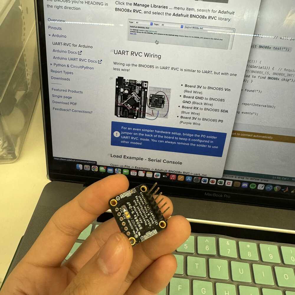
left: UART, center: UART-RVC (UART but one less pin and P0 is soldered on the back), right: I2C
We tried the UART-RVC interface on an RP 2040 and it worked fine. Unfortunately the RP 2040 does not have bluetooth for me to control it. Takeaway is that the ESP32-C3 is just super gimmicky… TA Leo from the Harvard section suggested to just use the PICO now… but its too late. We tried more things to just debug the most basic functions. Right now, both the ESP32-C3s I’m testing on are stuck in the wrong mode. They are not in download mode and we can’t figure out a way to get them back. The only way to upload to them now is to hold the boot button while it uploads.
Ok no. the one on my PCB is just not even taking anything anymore... keeps running into fatal error and the error links to the XIAO website and it says this error usually relates to a hardware issue...
Time check: 5AM...
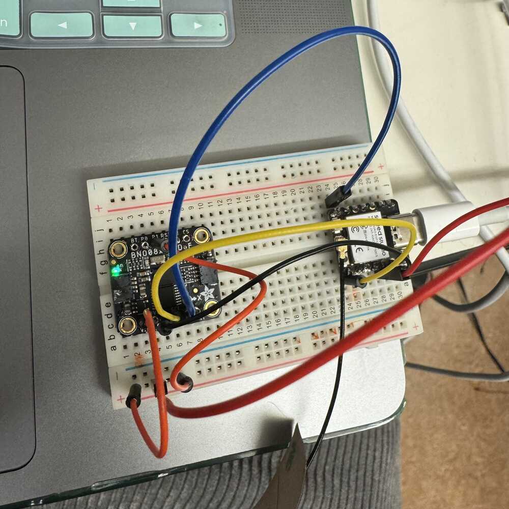
I'm so happy I started a conversation with Yohan. He's so cool. He made drone things for previous week and it's not even his final project. He was kind enough to with me with my IMU. He used I2C for his and although we got UART-RVC to work, it was just too gimmickly so I switched to I2C.

The problem with UART-RVC was in the example code. Apparently Serial1 was never happening so it blocked my code.
I switched to I2C and it started working on the ESP32-C3 on the side immediately but not on the board soldered to my PCB unforunately. I heat gunned it and removed it while melting my plastic and hot glue... D:. (Did I mention this is my 3 time heating and removing a piece?). Fixed some wiring. Did more surgery on my board. And boom got it to work. FINALLY.
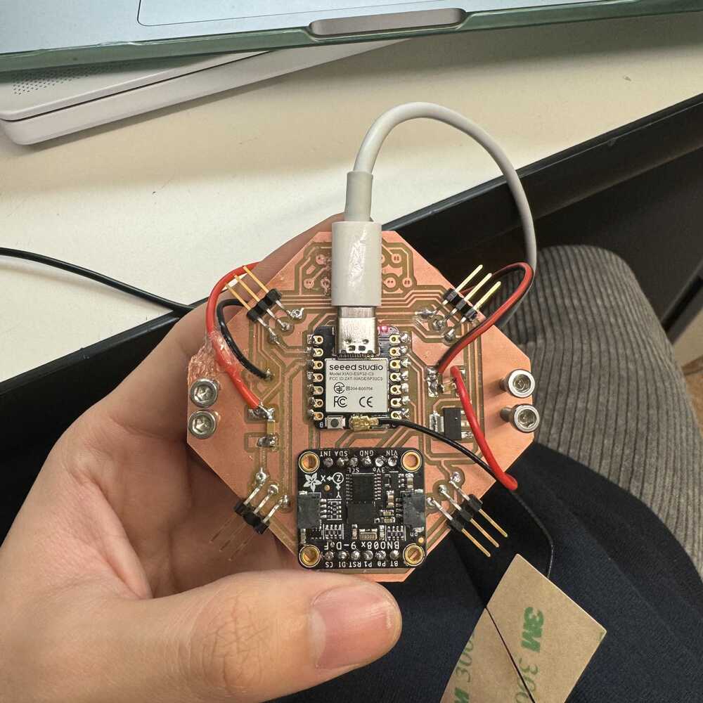
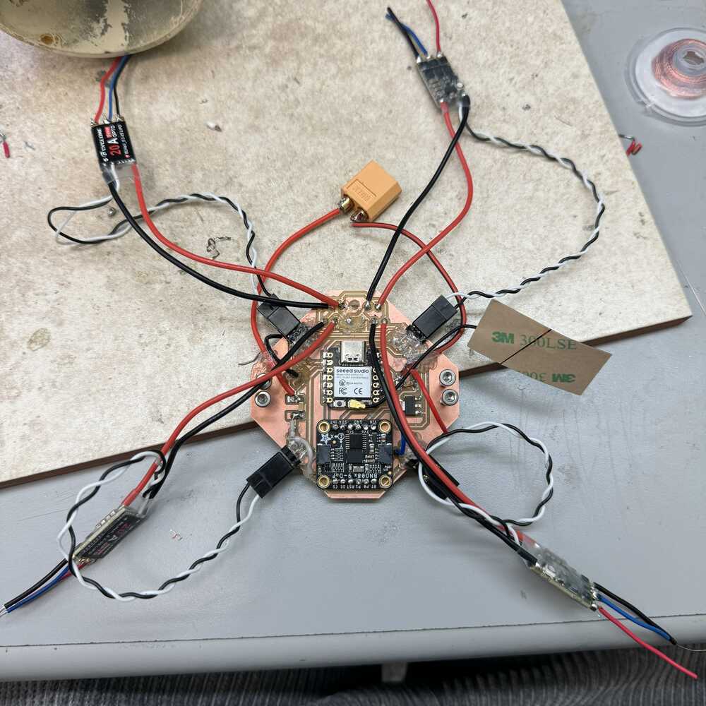
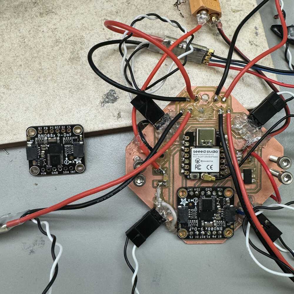
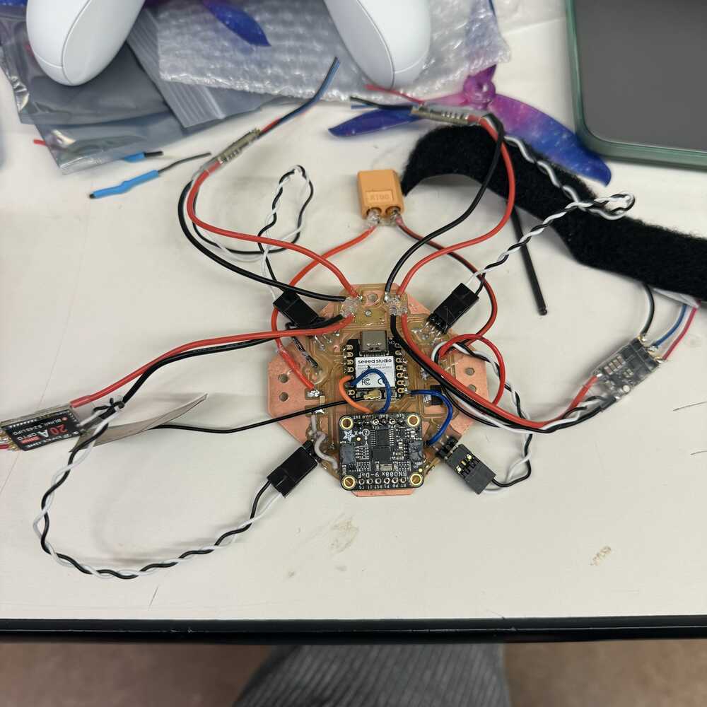
PCB and electronics all connected!
Flight Control
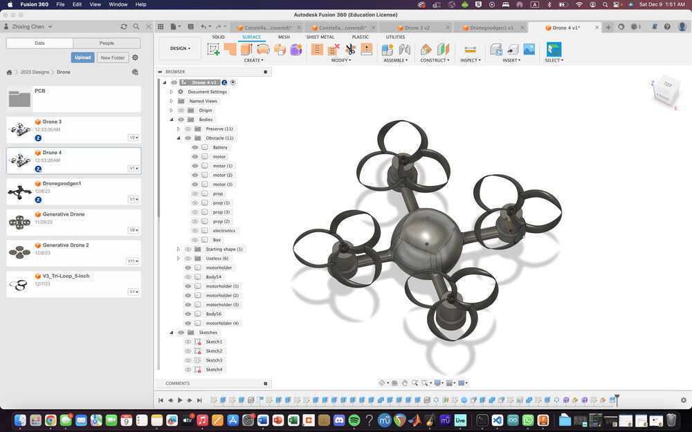
Finally integrated my whole system together! Just have the code left to integrate and finish... I technically have all the parts of my code but I need a way for them to all work together.
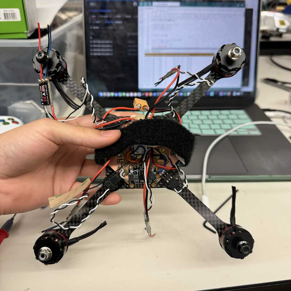

Weighing my drone

Actually came out a lot lighter than I calculated! Final weight is 372.2g and not 476.9g in my initial estimation (I think my chassis came out lighter yay).
The code
Here is the lastest version of my flight control code (that I did not get to finish). The foundation of my code is based off of Nicholas Rehm's dRehmFlight architecture with my own systems integrated in. I integrated my IMU BNO085, my specific ESCs, and my bluetooth controller.
I was able to find data on the functions of my IMU
- I need to still figure out the commandmotors function, here are the are 3 things to change:
- Controller functions are for radio communication (RC controllers), I need to use bluetooth, or i get RC controller
- They use a specific OneShot125 protocol to control their servos but I have ESC
- getIMUdata is different so I have to change it with my BNO085 code. done
End of my 28 hour long final push thoughts
It’s 9AM… no way I’ll finish this in time, but this has taught me alot… I learned a lot about system integration despite many bumps along the way and not actually making my drone fly. I learned a lot about programming, controls, communication protocols, inputs, outputs. I got really good soldering, I learned how to do surgery on my PCB board. I learned to use a power supply. I learned to use a multimeter. For now, imma just make the motors spin.