
Week 9 - Output Devices
Controlling a brushless motor with my microcontroller
This week, I want to figure out how to connect my 2300KV brushless motors to my 20A ESC to my ESP32-C3. Speaking with an EECS friend I bumped into, we came up with this circuit design for the ESC and motor.
PCB Design
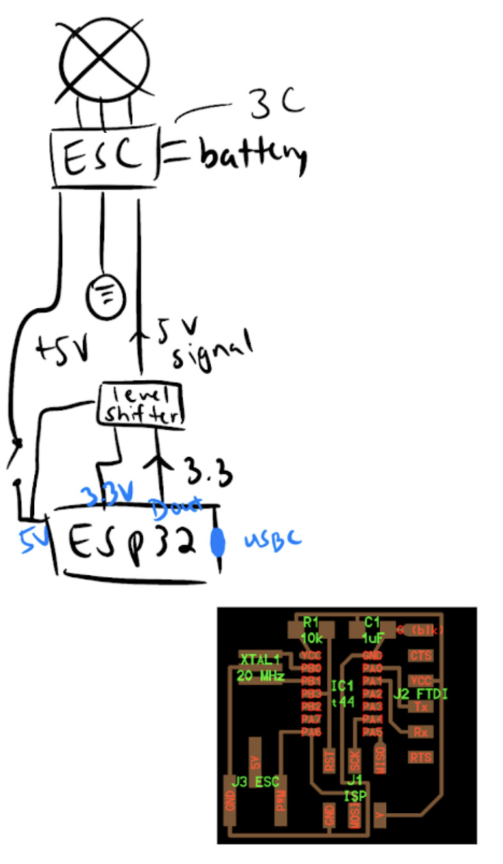
As I compared the design to Neil's design (the red one on the bottom) I noticed a lot of differences and the extra parts like the XTAL1, ISP, FTDI, resistor and capcitor made me confused. So I go to Jake's OH.
-
I learn that:
- Neil’s schematic is old, all the other parts are all built into my XIAO already so I don’t have to worry about them like the crystal, ISP, J2 FT01
- So for my schematic I really only need a 3 pin connector
- 5V can be empty to the XIAO because! my ESC is an opto isolator. The there is no direct connection inside.
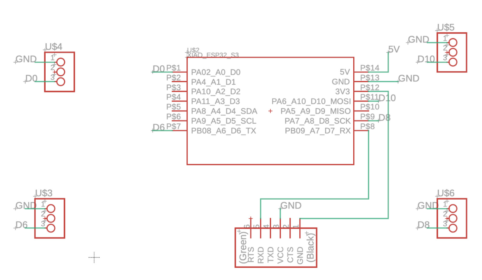
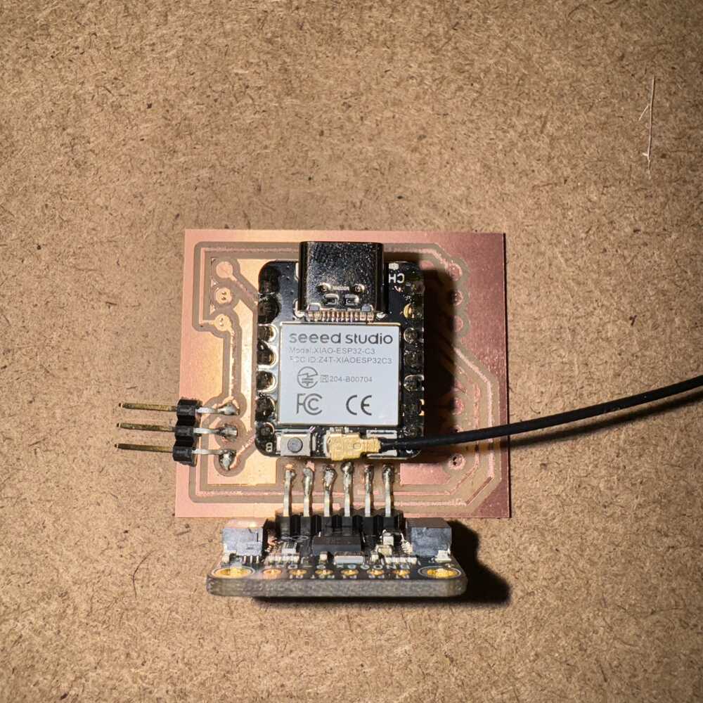
Here is my PCB schematic with the IMU and 4 ESCs
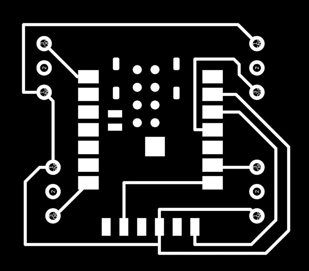
The one mistake I made with wiring last tiem was the trace width was too small, I thought changing them in drc did the trick but I realized I have to change them manually. To do this, I just selected each trace and on the inspector pop out on the right of Fusion, I was able to change the width from 6 mil to 16 mil. Wiring was fun and I moved things around. Here is the PCB design I made for my IMU and 4 ESCs. I continue to mill them. One weird thing was cutting an outline. Exporting the PCB outline give me a black box with a white line around it. I changed the inside (black part) to white as I usually do but the system would not detect it. I tried many things like making my white outline red or changing my board shape but the solution was to just click inverse colors in the mods page.
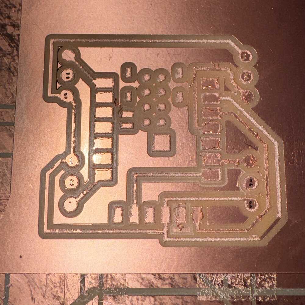
My motors and ESCs finally arrive on Tuesday and I can start testing them but this process actually took a lot longer than expected… The PCB did not come out the best. I think the endmill was not too great. But I think it is still usable. With all of my supplies, I try to connect my microcontroller to ESC to motor and battery.

After I got to the last part connecting the ESC to the battery I realized that I need a power distribution board. I did a lot of research and spoke to a lot of my friends for help and got a lot of different advice. I could buy a power distribution board. I could build a power distribution board, but also I should be careful not mess with power things. One thing in common however is that every path points to Anthony. So I find him for some help.
Controlling the motor
At first, I just wanted to ask for a XT60 connector and consult about building a power distribution board. Our discussion started there but we took a step back. I should start with just controlling one motor and not use the battery at all at first. I can power it with the power supply box in the other room. We have to make a mounting object for the motor and clamp it down. But before we got to that, Anthony gave me some insights on controlling the ESC:
I have to initiate my motors everytime by sending these signals, 1 ms high then 19 ms low, and 2 ms high then 18 ms low. After this I can control it.
He showed me a code from Matt Feng in 2021 that controls a similar ESC using arduino.
Then, we looked at my PCB and he showed me how to better solder things (I have to put more heat on the base copper). We run out of time after this so I will come back the next day.
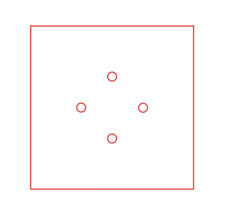
The next day... before spinning the motor, we need to make a base for it that screws in so we can clamp it down. I measure the screw that came in the packaging that goes in the motors.

I take some more measurements and quickly draw out the design in illustrator.
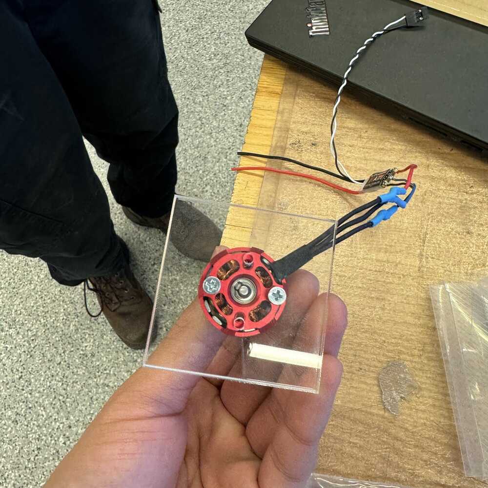
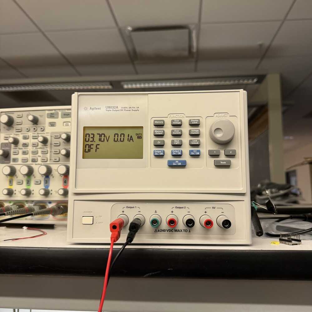
We screw the motor in (realizing that my holes are a bit off because the motor is not symmetrical but it should still work) and we take it to the power supply. Hook everything up. In the image you see 3.7v but we actually needed a higher voltage to run it.
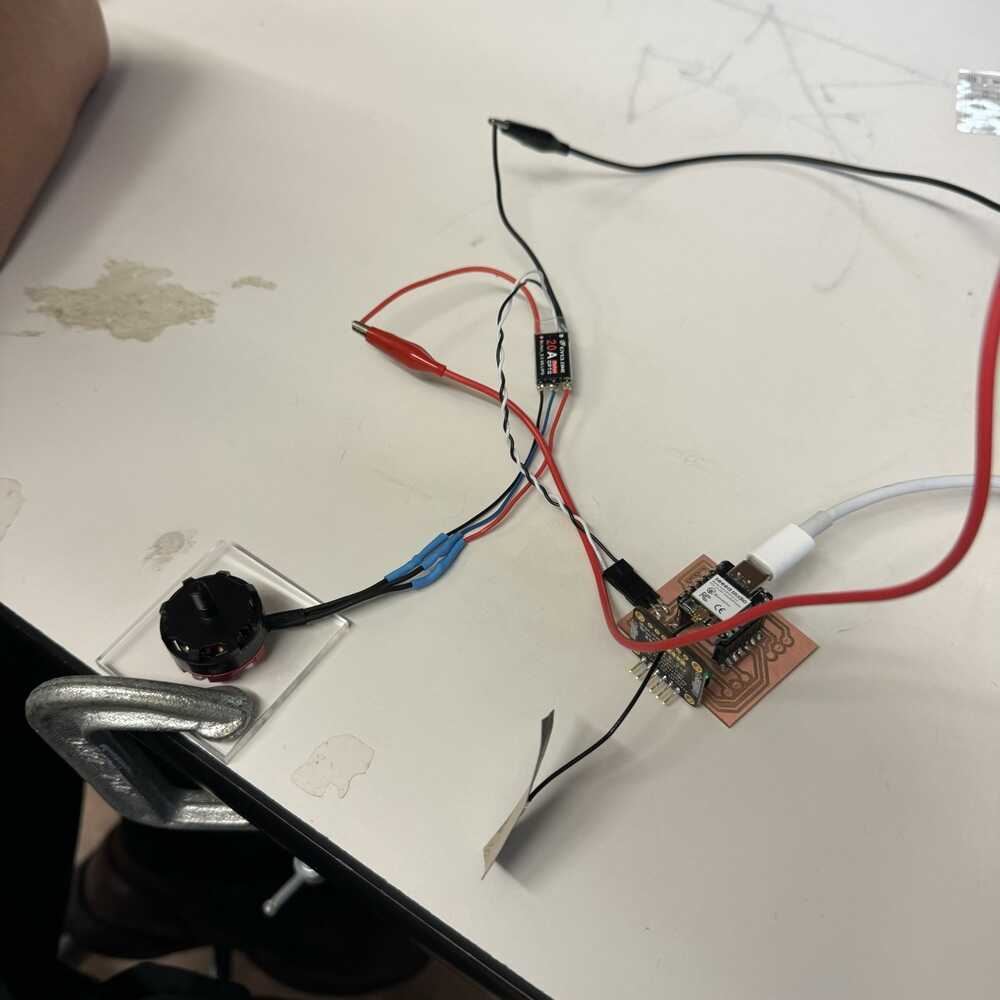
Motors spinning!
Week 9 Final Thoughts
Overall, week 9 was challenging but I managed to pull through with the help of a lot of people (mainly Anthony). Going through the process of connecting one motor and ESC helped me focus on one task and understand the concepts behind it. From here I will design my own power distribution board and then try to run 4 motors at a time!