
Week 2 - Embedded Programming
Preface
I have a pain point. I hate walking out of my dorm room to the single bathroom next to mine to find out that it is occupied and then walk the walk of shame back to my room.
Microcontrollers
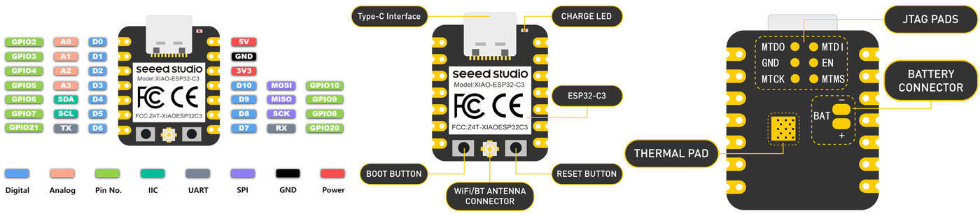
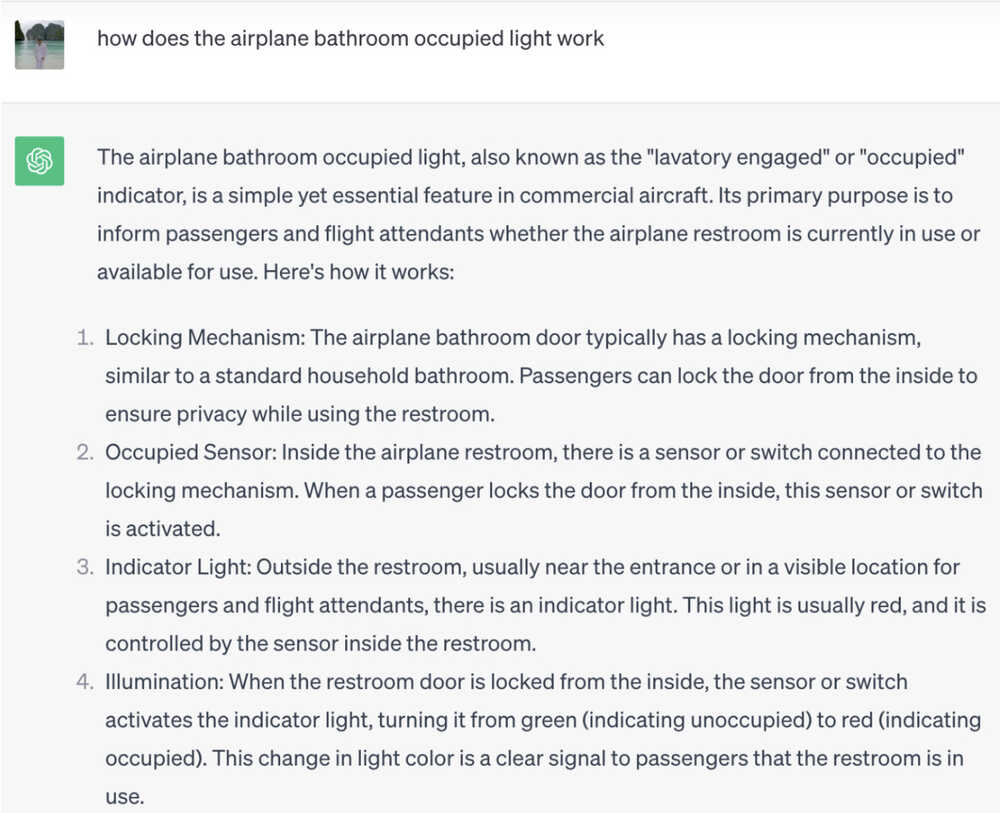
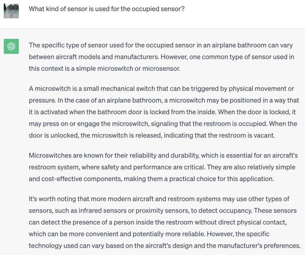
For Week 2, I begin with three options for microcontrollers: SAMD21, ESP32-C3 and RP2040. I went with the ESP32 because it has built-in wifi and bluetooth support. How perfect. This is how I start my journey to let me always know whether or not the bathroom is occupied from the comfort of my room. I want to make an airplane bathroom occupied light connecting the single occupancy bathroom next to my dorm room. A theory quickly forms in my mind: hijack the bathroom lock and put sensors and whatever in it and it will send a bluetooth signal to a lasercut cool toilet sign that changes colors in my room. To help us better understand how it works, let’s ask ChatGPT (because Google did not help)
 The summary supports my theory… but I have a bigger challenge. I feel like the sensor, mechanism, and light are all connected through wires inside the walls. For me, I probably shouldn’t drill through the walls (thus needing bluetooth). Also, I will need power for the electronics and it will be difficult to fit the whole design inside the bathroom lock. So, I will make a first prototype that sits outside of the door.
My plan is to get the first prototype this week while completing the task: write program for a microcontroller development board to interact (with local input &/or output) and communicate (remotely). Afterwards, when we learn about PCB design, I can potentially make a small version to fit right inside the door (and also figure out the power problem).
Browsing through the data sheet for ESP32-C3
I have to understand more about my microcontroller (or what a microcontroller even is) so I read the datasheet. I do not remember much after reading it… so I downloaded the datasheet as a PDF so I can use chatpdf.com to interact with it and utilize it further.Electronics and Programming
Found a tutorial on using ESP32C3 with Arduino IDE (which I have a little experience using before so I will start with this.
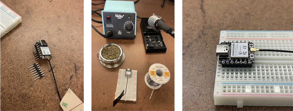
ESP32C3 does not come with headers so I soldered on pin headers first.
The summary supports my theory… but I have a bigger challenge. I feel like the sensor, mechanism, and light are all connected through wires inside the walls. For me, I probably shouldn’t drill through the walls (thus needing bluetooth). Also, I will need power for the electronics and it will be difficult to fit the whole design inside the bathroom lock. So, I will make a first prototype that sits outside of the door.
My plan is to get the first prototype this week while completing the task: write program for a microcontroller development board to interact (with local input &/or output) and communicate (remotely). Afterwards, when we learn about PCB design, I can potentially make a small version to fit right inside the door (and also figure out the power problem).
To connect Arduino to ESP32, I installed the ESP32 board package to Additional Boards Manager URLs: https://raw.githubusercontent.com/espressif/arduino-esp32/gh-pages/package_esp32_dev_index.json
Circut Diagram and Code in Arduino IDE

Blinking LED Program
Adding Input
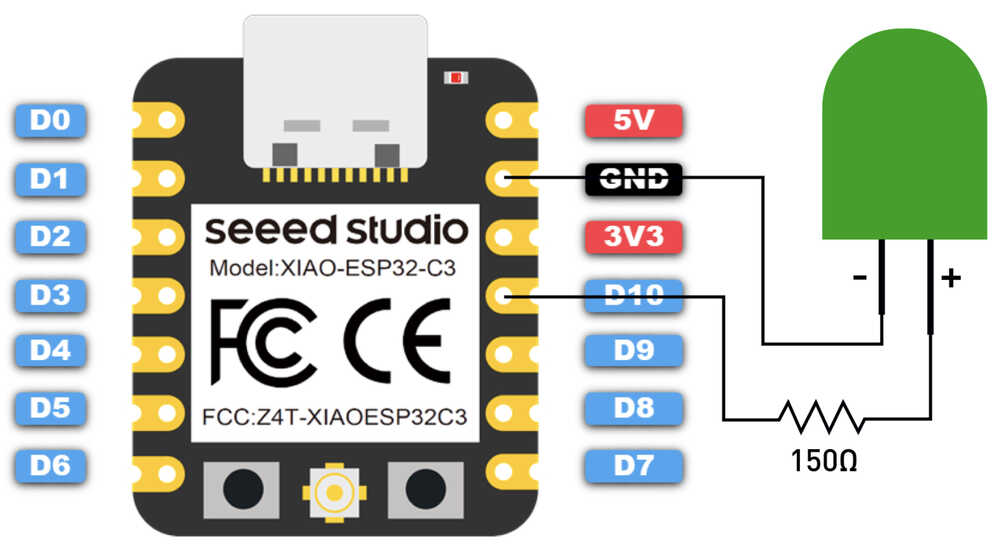
Now, I update the code to add a phototransistor to D1 that will act as a switch to turn on and off the LED. When the phototransistor detects a lot of light, it the LED will be off, but once I cover the phototransistor with my hand (making the light low), it will turn the LED on.
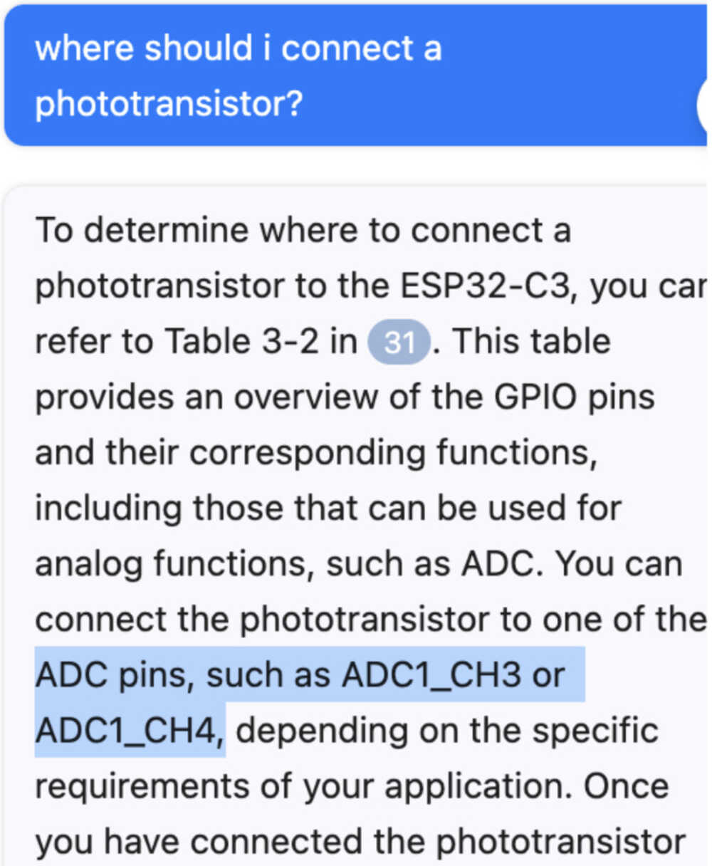
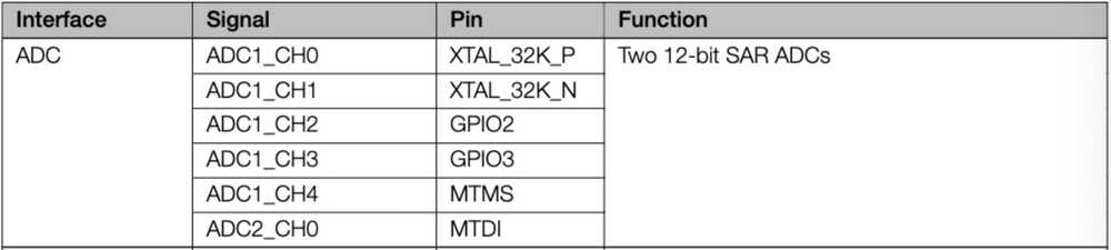
I go deeper and try to prototype my idea by connecting the phototransistor to one of the ADCs (ADC1_CH3, which is GPIO3 which is D1).
New Code
New Circut (want to use the left circut with increasing illuminance)

Three iterations of the circut with the 3rd (right) one working
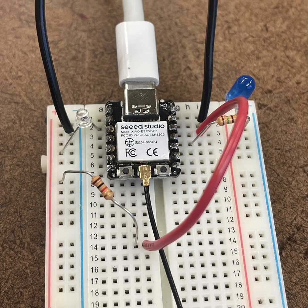
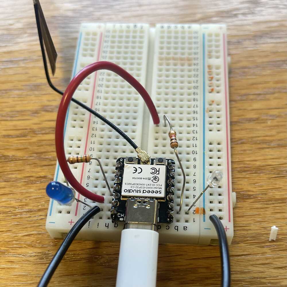
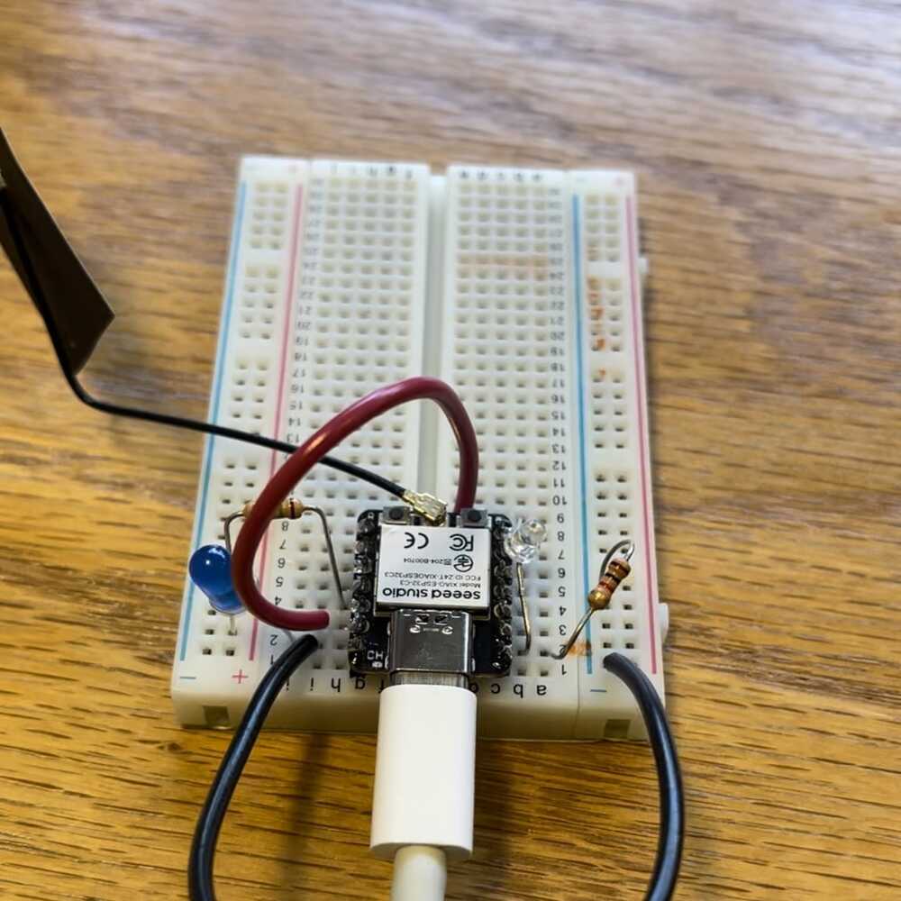
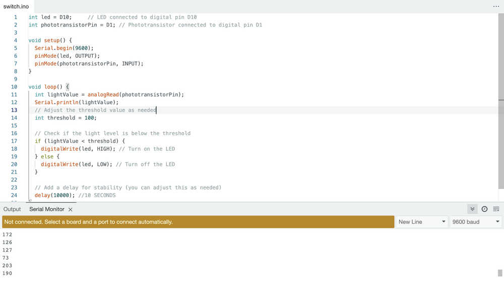
Figured out the right configuration for my circut at the EECS shop with Anthony. The image of the whiteboard is our ideation. Middle image is the right circut where voltage increased with decreasing illuminance . I wanted illuminance to have a positive correlation with voltage such that when I would block off light to the phototransistor, my reading would drop. And once the lightValue drops below 100, the LED would light up!
Light Sensing and Switching on LED Program
As usual, I ran out of time this week but I was able to accomplish some basic funcationalities of the program. Taking an input and turning on the LED. Next steps are to figure out Bluetooth, have a remote input turn on my LED, and how I would be able to power the system.