
Week 8 - Input Devices
Connecting Adafruit 9 DoF IMU to microcontroller
After some research, I learn more about the three communication systems: SPI, I2C, and UART. Anthony's insights and my research helped me pick SPI to use for my drone because it is the fastest and would be nice for flight stabilization. I am a bit concerned that I might not have enough pins for everything though... To connect the microcontroller and IMU, I reference the Adafruit 9-DOF Orientation IMU Fusion Breakout - BNO085 Datasheet

-
Using the guide on the datasheet, here is my wiring.
- Vin, P0, and P1 connected to +3V3
- GND to GND
- SCL connected to SPI SCK
- SDA connected to SPI MISO
- DI connected to Pin SPI MOSI
- INT connected to Pin 3
- CS connected to Pin 4
- RST connected to Pin 5

Here is the example code with pins changed and i changed to SPI
IMU SPI connection working!
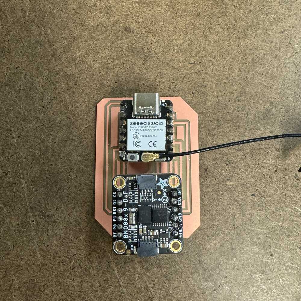
For the first iteration, I just worked with breadboard to make sure that I learn how SPI connection works and that I can actually get it to work without making a bunch of PCBs that fail. From here, I transfer the wiring that works to Eagle and I make my PCB there.

To make wiring easier, I move INT to D7 and CS to D6. To align the two 6 x 1 connectors, I found this image on the IMU page. To align the two 6 x 1 connectors, I found this image on the IMU page
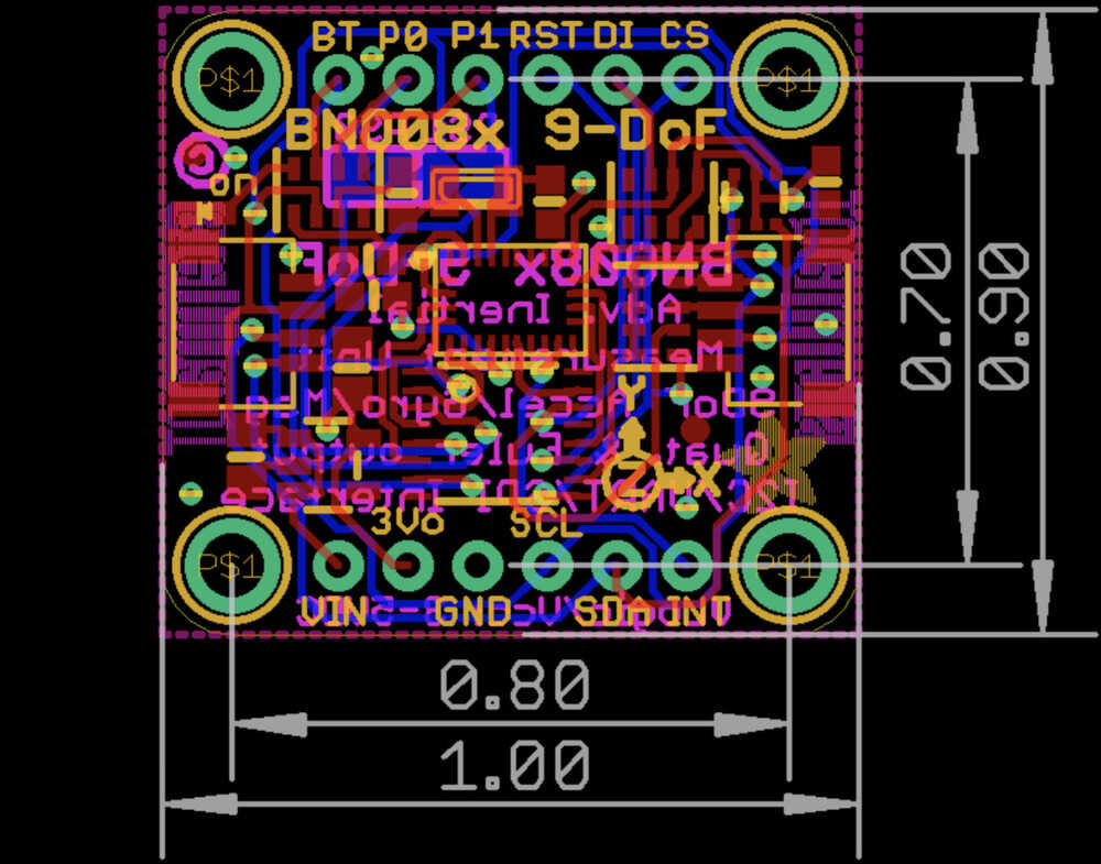
I used dimension command to measure the distance between the two sides of the IMU
PCB Design

PCB Fabrication


The 1/64 cut the traces really well this time (I picked a good end mill yay!) However, my outline got messed up, the calculation in the mods missed the top so I just cut it out on a bandsaw. Then I solder some connectors on the board.
BUT... it doesn't work...
I was trying to debug but class happens and I present my findings in class. I get feedback to just use UART actually it is much more simpler so I will redesign a PCB that uses UART instead of debugging this. Before moving to UART, I tested the new wiring (CS to D6 and INT to D7) on my breadboard to test if it works and it does. It works just like the previous one. So this means something in my PCB is wrong.
-
Here is my wiring for the UART (based on the datasheet again):
- Vin and P1 connected to +3V3
- GND to GND
- SCL connected to TX
- SDA connected to RX
I try to test this new wiring but my ESP32-C3's connection broke somehow. My arduino won't pick up the connection via the USB-C. Trying a different cable did not work. But the old cable works for a different ESP32-C3. I will use what I have learned to design a full PCB with an ESP32 soldered on to it for my drone.