
Week 5 - Electronics Production
Characterizing my PCB Machine (Modela MDX-20)
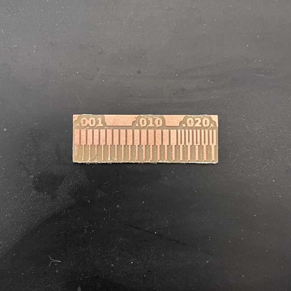
With a group, we cut a test copper piece to understand the constraints of copper width. We cut a range of lines from .001 to .020 inches. As the trace width got smaller, the copper started peeling off the board because there wasn't enough area to support it while being cut.
Fabricating my PCB
Fabricating my PCB I missed one step last week: to prepare my board outline for fabrication. I used photoshop to fill in my board completely with white. One problem I encountered was that when I imported the PNG from my desktop into photoshop, it wouldn’t let me edit the image because it was in indexed color mode. After changing the mode to RGB color, I was able to use the paint bucket tool to click inside and easily fill it with white.
Before and After

I follow this tutorialto cut my PCB on the Modela MDX-20. When setting my origin, I realized that I want to conserve as much space as possible so I cropped the borders of png.

The set up was the most important part and I trained with Jen twice as I missed parts of my first training. The html interface connected to the Modela looked scary at first but the training and tutorial helped a lot. Here are the main steps for getting my board to cut.

Summary of Process
The 1/64 in bit was first installed carefully using a hexkey. I move the z down and leave enough space for the bit to move a like 5mm down. I imported my tracespng in mods on the Linux computer connected to the MDX-20. I opened a preset terminal that connects to the machine and clicked "open" under the serialserver on the right side of the mods page. This connected the mods to the machine. From here, I set the origin of the cut using x and y in the fourth white box and z using the up and down controls on the machine. One the origin is set, I bring the bit down and press it into the board a little bit (advice from Jen), which will help with cutting the traces. Remember to select "mill traces (1/64) in the set PCB defaults box!!! Now click calculate in the middle and the mods will generate the gcode for the fabrication. View to check that everything is good and hit "Send File!"
Attempt 1


The board didnt really cut well and it looked skewed to the top right. After troubleshooting and thinking about the different ways it could have messed up, I concluded that the board was slightly slanted because of the tape under it. I underestimated the size of my board and the tape did not cover the board evenly. Also, this was an issue when cutting out the middle rectangular outline. The board lifted up and got caught in the machine when this happened and I instantly stopped the machine by turning it off.
Attempt 2
Learning from my mistakes, I give it another go. Now I am pretty comfortable with the setup and mods interface.
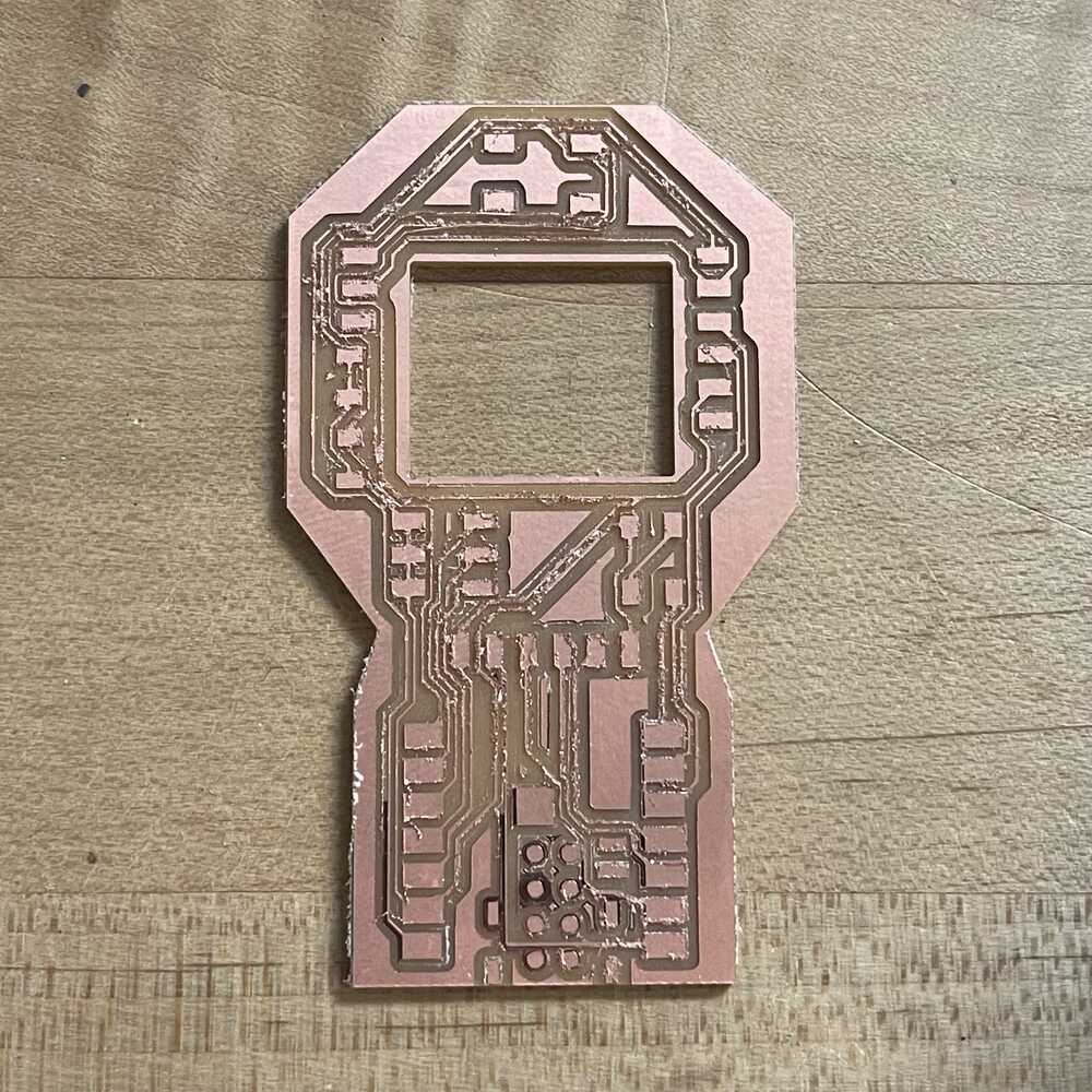
I avoided the previous error and the board cut without lifting up and the base seems even. However, in this cut, the drill bit might be a bit more dull. Nonetheless, the second attempt made me realize that my traces might just be too thin. I have learned a lot about PCB fabrication and I'm running out of time so I will move on to soldering.
Soldering
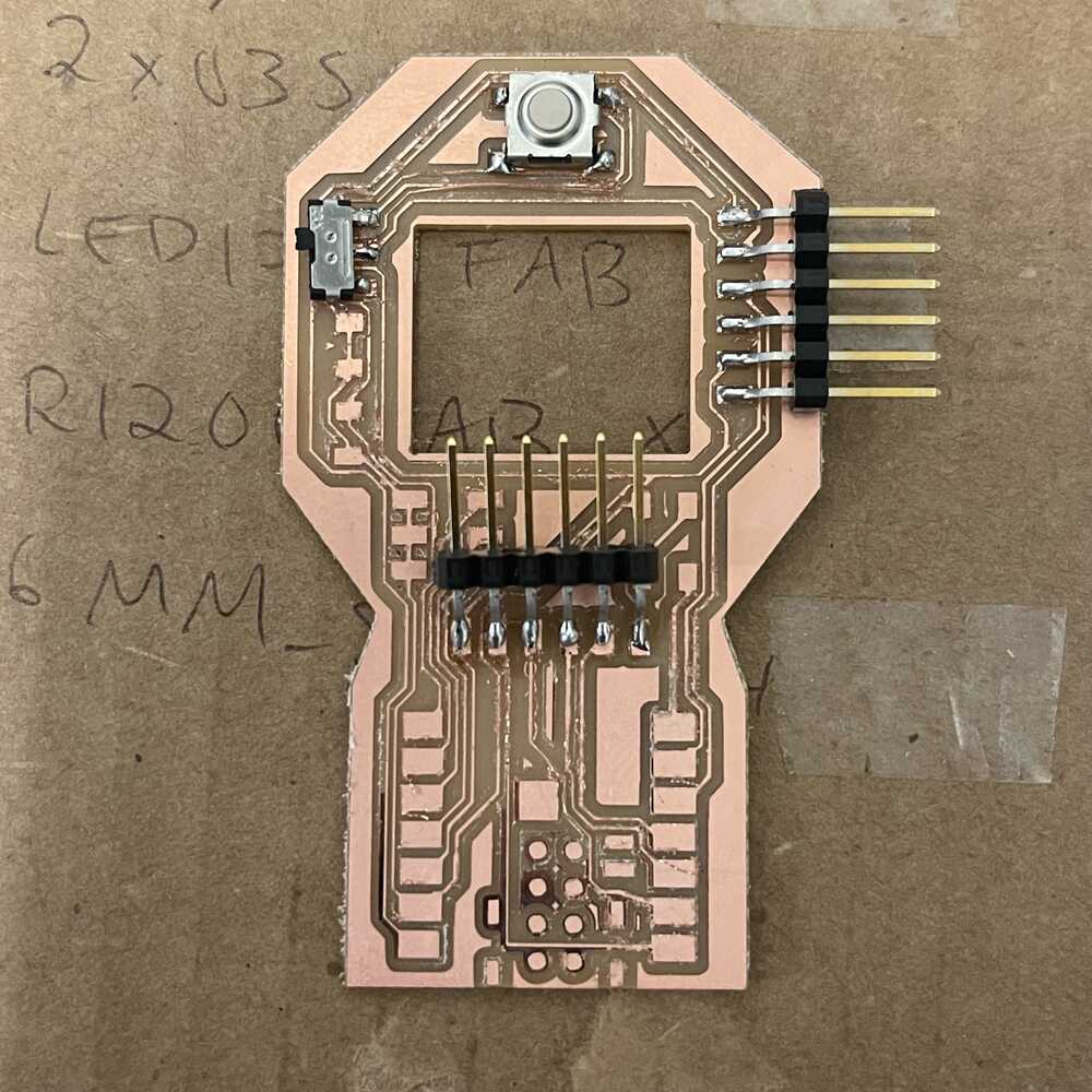
For the final part of Week 5, I wanted to practice soldering on the PCB even though it won't work. I searched for components that are part of my board.

I could not find some component so I just practiced with whatever I could find.
My finished but not completed PCB
Week 5 Final Thoughts
Overall, this was a rough week with my midterms and other projects going on. But I am happy I went through the process of fabricating the PCB I designed in Week 4. I used the machine so many times that I feel comfortable on it. Many other failed attempts were not incldued and I spent a lot of time troubleshooting and figuring out random things. Even though my board doesn't work, I learned what works and what doesn't along the process. The fabrication helped me gain a better understanding of designing boards as well.