Week 2 - Computer-Controlled Cutting
Laser Cutter
For this week's assignment, we were tasked with using computer-controlled cutting in two different modalities. We had a training session at CBA and got acquainted with the Spirit Laser Cutter (CO2 laser), playing with some of the settings in order to understand what works best with our material for this week, ~4.25mm thick cardboard. The recommended settings on the CBA computer are speed 2.5%, power 100%, pulses per inch (ppi) 200. However, I found that those settings were insufficient to cut the cardboard in one pass and resulted in some smoke/burn in the cut line. For my project, I preferred decreasing the speed to 2.3%, the power to 70%, keeping the ppi the same, and doing 2 passes for a cut. The result was cleaner and the burnt cardboard smell was significantly decreased. After the training session, my group also observed the distance from the bottom of the aligning tool to the top of the material that will be cut is 17 mm (focus distance), and that the kerf was approximately 0.01in or 0.25mm. The kerf was used for consideration in my design so that parts could be held together by press-fit joints.


For the geometry of my laser-cut construction, I was inspired by these spin-top chairs that are in the atrium of the Media Lab. I used Fusion360 for my 3D modeling to create a model entirely made of concentric rings (united by external or internal supports). The rings were arranged in such a way to resemble the spin-top but could be switched in order. Even with some previous CAD experience in other softwares, I had to get used to Fusion360 tools, and using joints (as opposed to Solidworks mates, for example) is something I have not yet mastered. Using a parametric design was really helpful when I was adjusting some parameters such as the number and height of layers, thickness, kerf, depth of joints, etc.

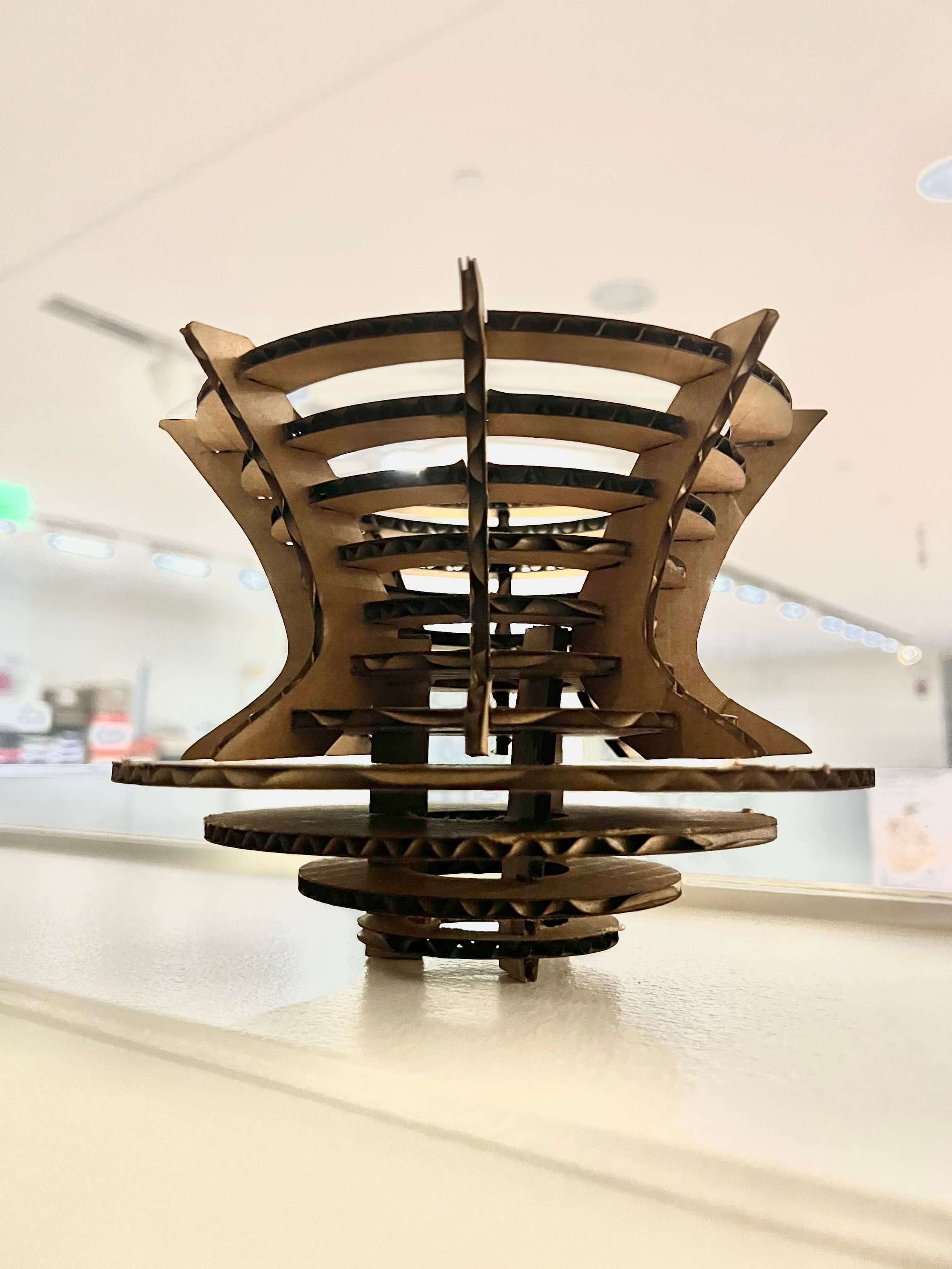

After finding the sweet spot of parameters for the laser cutter, my next hurdle was actually assembling my piece. The concentric rings could be connected internally or externally, but I have found that putting 8 press fit joints in a tall stack of rings at once could be very tricky without something to either hold the rings at the correct height or align them. Some of my takeaways are to create a sacrificial tool (like a T-shaped hanger) that could be used to stack the rings correctly and could be destroyed after assembly, and also to use chamfer joints, to allow for some flexibility in assembly when some of your joints are close but not quite aligned.

I was satisfied with my final result as the rings in the lower part look like they are floating on air and the upper rings make a nice shape that can resemble the desired spin chair shape (especially when they’re side by side). With more time, I would work to improve the sturdiness of the shape and try some different ring alignments (e.g. making the rings resemble a Christmas tree).
Vinyl Cutter
For this week's assignment, we were tasked with using computer-controlled cutting in two different modalities. For the vinyl cut task, I wanted to create a sticker of the skyline of my hometown of Salvador da Bahia, highlighting the most famous tourist spots.


 I found a cartoon image and used vectorize.io to raster the shapes, and after extensive line cleaning at AutoCAD I kept the most important geometries.Using the Roland GS-24 Vinyl Cutter, I played a bit with the force applied because the initial settings (20 mm/s speed and 80 gram force for pressure) created a shallow cut that made the weeding process difficult. Increasing the force to 100gf resulted in a nice, clean cut.
After successfully cutting my first piece in the blue vinyl, I decided to use some different colors for my stickers in honor of my colorful hometown. Below is the final result on my computer!
I found a cartoon image and used vectorize.io to raster the shapes, and after extensive line cleaning at AutoCAD I kept the most important geometries.Using the Roland GS-24 Vinyl Cutter, I played a bit with the force applied because the initial settings (20 mm/s speed and 80 gram force for pressure) created a shallow cut that made the weeding process difficult. Increasing the force to 100gf resulted in a nice, clean cut.
After successfully cutting my first piece in the blue vinyl, I decided to use some different colors for my stickers in honor of my colorful hometown. Below is the final result on my computer!

Files for this week can be found here