Week 6 - Electronics Production
For this week, we are fabricating a PCB board, and like last week, this is a totally new set of skills I have yet to master. If we were satisfied with the board from the electronic design assignment, we could have used that, but after a realization that my board from last week was too ambitious (and incomplete), I decided to create a new design for the board I am producing. My previous design had 2-layers and vias, which were through holes that needed to be drilled, and besides that, special PCB stock (with copper on both sides) needed to be used.
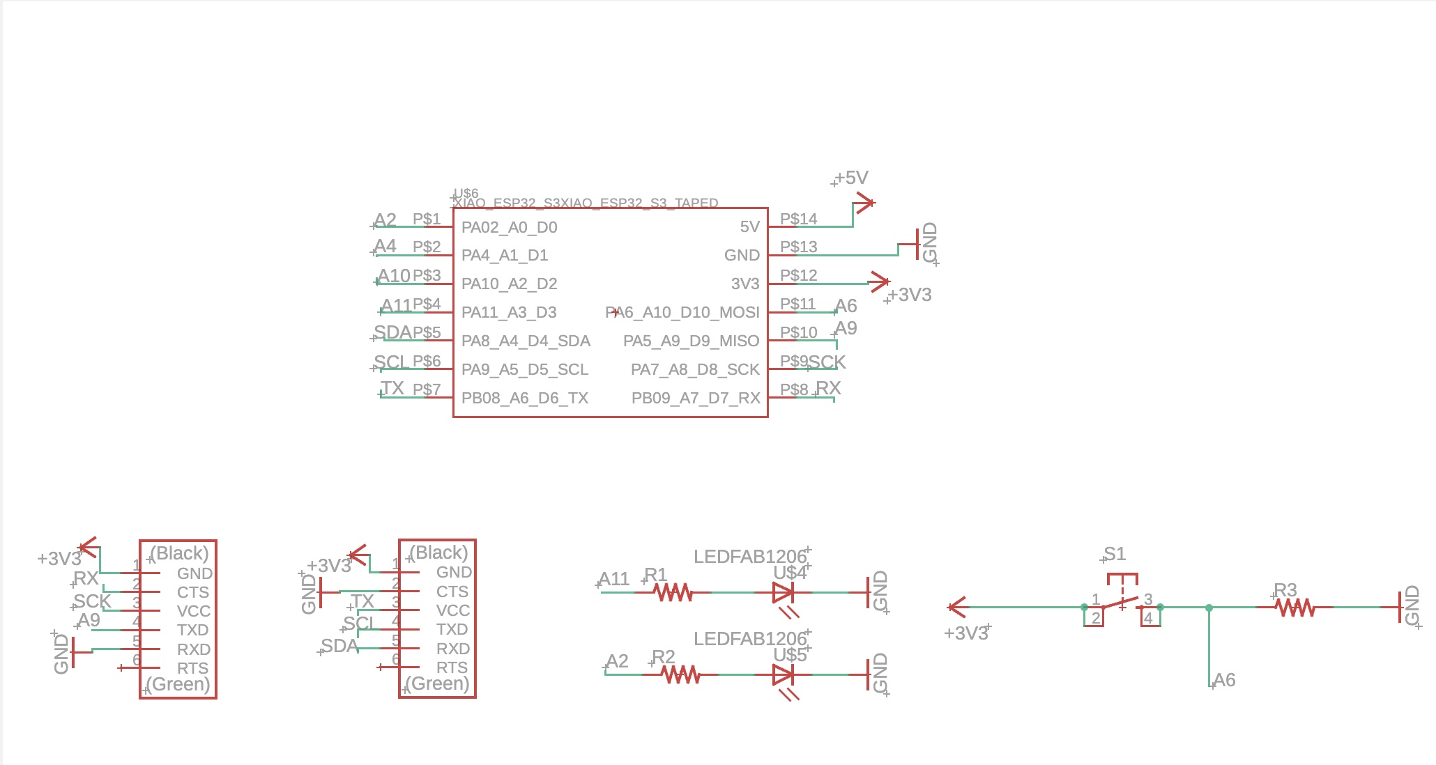
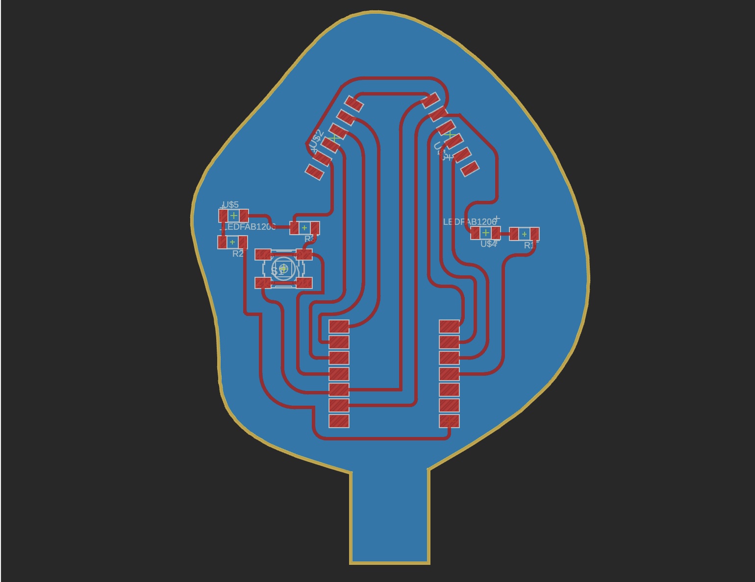
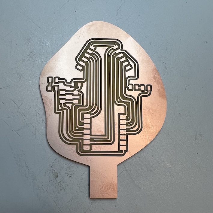
For the new version, I changed my microcontroller from the XIAO RP2040 to the XIAO ESP32S3, as the latter still has a thumbnail-sized profile, but the added capabilities of Bluetooth and Wi-Fi (which might be needed for my final project in the communication of a drawing with a viewing board). Inspired by the example board that Neil showed in class, I decided to create a board that had various connectors, with access to power, ground and pin ports, so that this PCB, if successful, could be used in in upcoming weeks, as it would be able to connect to sensors/input/output devices and communicate with my microcontroller. I also added two LEDs and their accompanying current limiting resistors and a push button. I tried to arrange my components and outline so that the board would resemble a tree.
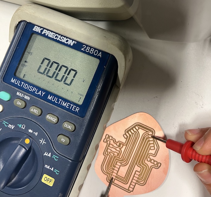
The recitation helped us to identify some strategies to debug our PCBs, which include spotting issues by illuminating the board against light, using the multimeter (in continuity mode) to know if your traces are actually connected, and importing the class DRC to make sure the traces/clearance are compatible with the machines we are using. We also learned strategies to recover from minor problems in PCB milling, like using an exacto knife to continue cutting a trace and jumper wires to add a missing connection. On the PCB mill training, we also learned, among other things, how to change tools, probe Z0, and the various ways one can export their manufacturing files (eg Gerber) from an EDA tool and transform the traces into X,Y,Z instructions (Gcode). My workflow was to use the ULP for Eagle provided by Anthony to generate PNGs and then use those in the mods “mill 2D PCB” program.
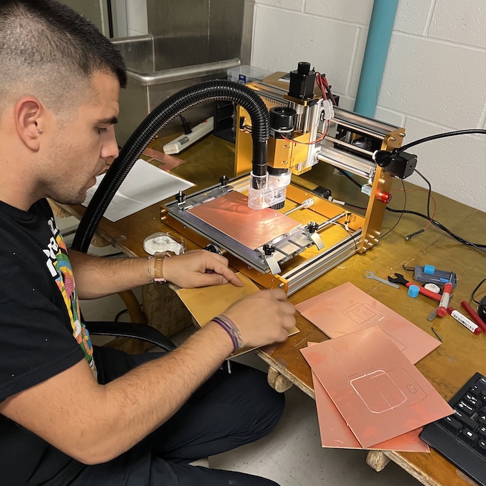
My first trial of making a PCB was delayed due to an imbalance in the base of the CBA milling machine, which meant that a pass would not go actually go through a section of the board that was too distant from where the Z0 was set. After Alfonso fixed that buy using an acrylic base and double-sided tape to avoid curvature of our copper stock, I went and cut my first traces. To no one’s surprise, I soon encountered problems: my traces, though they had previously been approved in the Design Rule Check, looked dangerously thin when I was milling my board. Later, I learned that I most likely had mistaken my actual traces and the sacrificial lines (the non-connected copper lines that remain after passes of my 1/64 drill, which should and would most likely been removed had I let all my passes finish). In any case, I stopped my drilling then and separated my lines a tad more to make sure that I would not run into any problems.
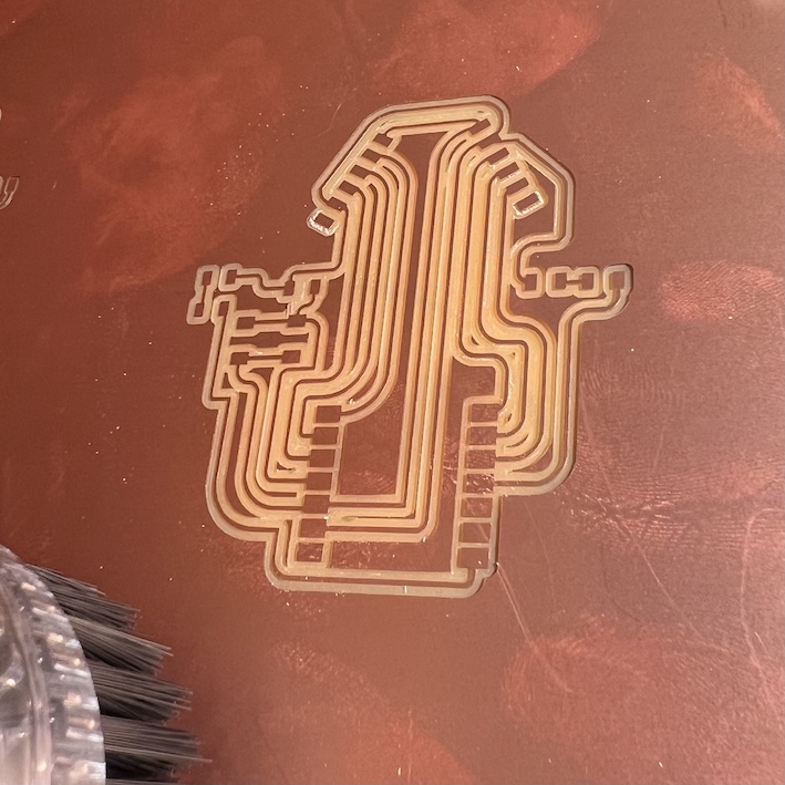
After 40 (!) minutes of milling my traces, the result came out pretty satisfactory, and I checked with the multimeter that all my desired traces were connected (side note: if you want to improve your milling time, make a few passes with the finer, 1/64 tool and then change it to the 1/32 bulkier one). Next, it was time to do some soldering! Thankfully I had people in my lab that walked me through the process and my soldering experience was not entirely ~terrible. I was told I need to leave the solder tip in contact with my part maybe a few seconds longer so that the solder can flow a bit better. Below you can see the final result!
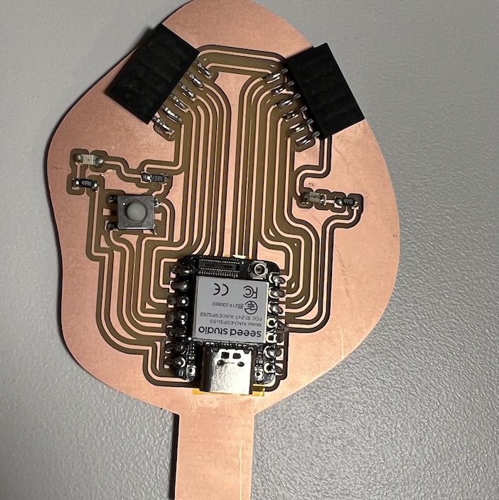
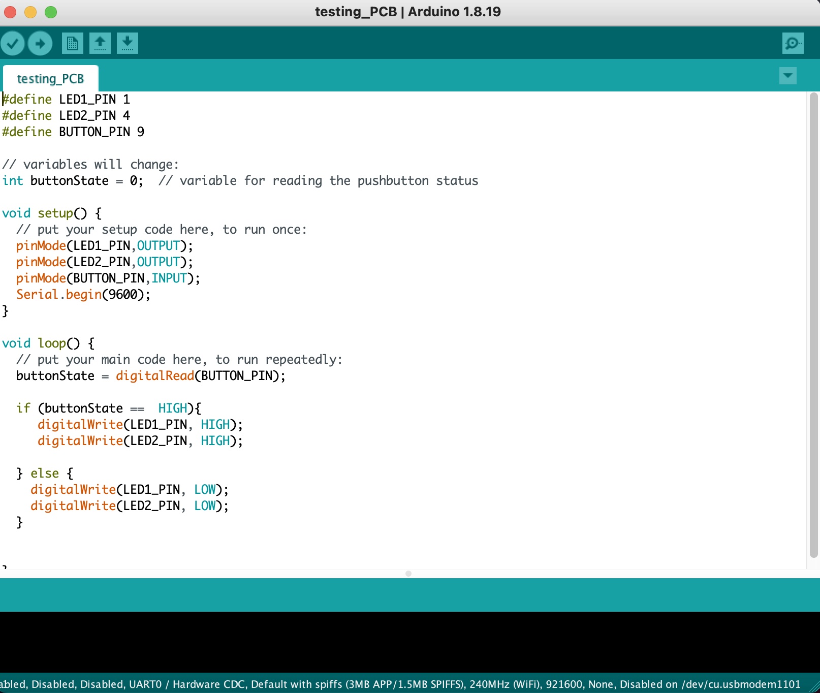
The last step was to test my microntroller + PCB, for which I used Arduino and the simple code below, which would turn on both LEDs when the push button was pressed. One important thing to note! The ESP32S3 PIN labels in my Eagle diagram were actually not the actual GPIO labels, I discovered very quickly. So I had to refer to the pin list in Seeed’s website to actually get it to work. This is the final result!

Files for this week can be found here