Week 9 - Input Devices
This week, we’re building up on previous knowledge from electronics design and fabrication to integrate a sensor into our circuitry and read it. I decided to try to tackle one of the components of my Final Project, which would be a palm reader surface that would take some biometric data to try to identify your “mood” or “aura”. After discussing what type of sensors I could use with Quentin, I decided that I want ideally to use a heart rate and a temperature sensor (sensitive to body temperature differences) to be able to catch enough information to display LEDs associated with the condition of the user. For this week, I tried (and didn’t succeed) to integrate an NTC (Negative Temperature Coefficient) thermistor into the circuit I made for week 6.
NTC thermistor is a heat-sensitive resistor whose resistance decreases as temperature increases. This relationship is not linear and can be described by an exponential function
R1 = R2 • exp(B• (1/T1-1/T2))
where R1 = NTC Resistance in Ω at temperature T1 in K, R2 = NTC Resistance in Ω at reference temperature T2 in K and B = B value in K, Material Constant of NTC thermistor
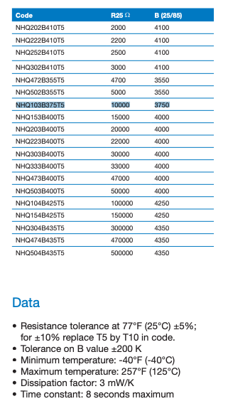
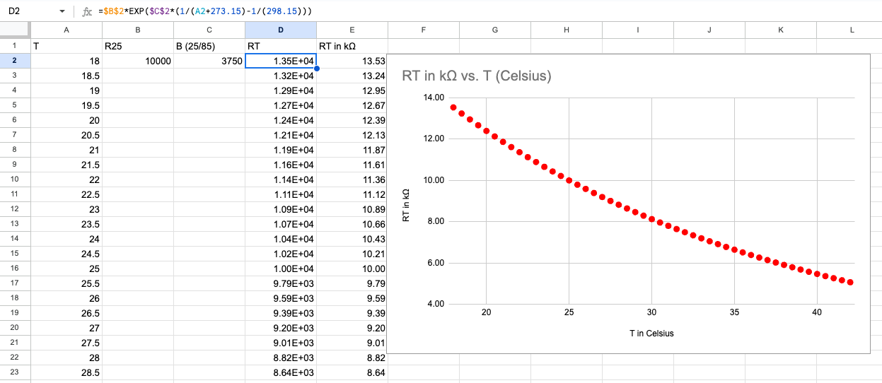
B is a material constant within certain ranges and when it is calculated from 25°C and 85°C is expressed with the denotation B25/85. Looking at HTMAA’s inventory, the provided thermistor is theNHQ103B375T10 , and when we look at its datasheet, we encounter the value of the resistance at 25°C to be 10kΩ and the B25/85 value to be 3750. From that information, we can plot the expected resistance of the NTC to be at different temperatures.
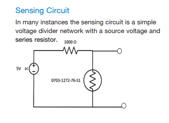
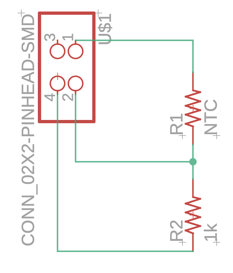
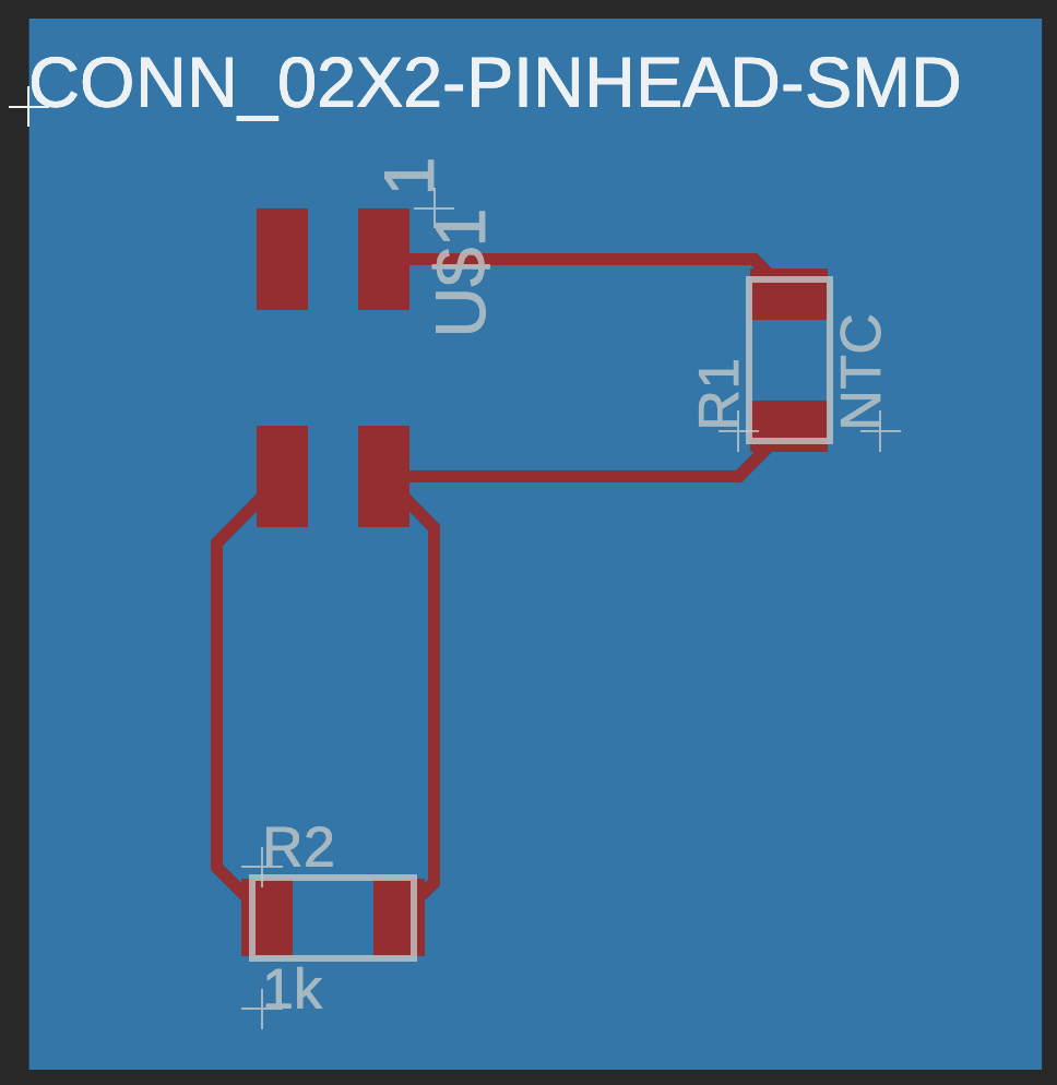
From our office hours with Jake and looking at some of the thermistor documents, it is clear that the simplest sensing circuit needed is a voltage divider with a reference voltage, a known-resistance resistor and the NTC in series and the pin that will read the voltage between them. For my application, the circuit would look like this:
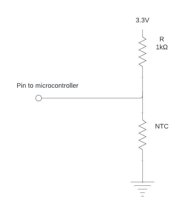
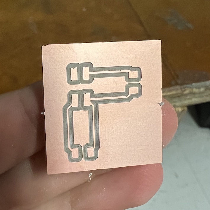
I fabricated this circuit and integrated it with my previous tree PCB from week 6, which has female connectors for analog pins, 3.3V and GND. The microcontroller is the ESP32S3, and the code I used to identify the resistor and temperature from the voltage reading is as follows:
//Thermometer with thermistor

#define RT0 10000   // Ω
#define B 3750      //  K
#define VOLTAGE_PIN 8
#define VCC 3.3    //Supply  voltage
#define R 1000  //R=1KΩ

//Variables
float RT, VR, ln, temp, T0, VRT;

void setup() {
	Serial.begin(9600);
	T0 = 25 + 273.15;                 //Celsius to kelvin
}

void loop() {
	VRT = analogRead(VOLTAGE_PIN);       //Acquisition analog value of VRT
	VRT  = (3.30 / 1023.00) * VRT;      //Conversion to voltage
	VR = VCC - VRT;
	RT = VRT / (VR / R);               //Resistance of RT

	ln = log(RT / RT0);
	temp = (1 / ((ln / B) + (1 / T0))); //Temperature from thermistor

	temp =  temp - 273.15;                 //Conversion to Celsius

	Serial.print("Temperature:");
	Serial.print("\  ");
	Serial.print(VRT);
	Serial.print("C\  \ ");

}
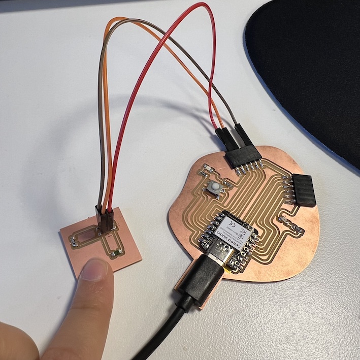
I was able to run the code only once, and my temperature reading was showing NaN. When I started to debug, my microcontroller stopped being able to communicate with my computer completely. I’ve looked it up and it seems a not-so-uncommon recurrence with ESP32, but unfortunately, I wasn't able to solve it before class. I was able to hook up my thermistor to a multimeter and show the real-time difference in resistance when the NTC is pressed by my finger. I have yet to see if this particular thermistor will be sensitive enough for my final project, but I have a lot to learn on the way.
New updates
After checking in with Quentin on my Midterm review, we decided it’d be best to change the microcontroller to the ESP32C3 to see if I’d be a little luckier this time. With his help to desolder and resolder the new board, it seems that the exchange was a success and my ‘tree’ PCB is working fine again! However, we also discussed how the NTC from the inventory did not look at all like a 10k Ohm NTC, since when we measure with the multimeter we get around 100k Ohms. After all, I was not able to debug everything and moved on to implement my pulse oximeter, the MAX30102
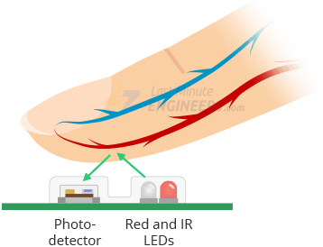
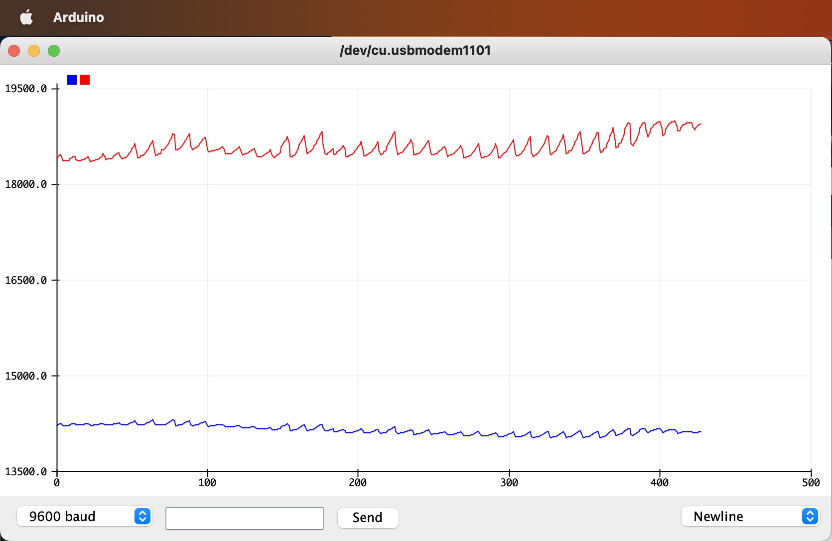
For the MAX30102 module, the way it works is that it has a red and IR LED which can shine on regions on the body where the skin is thin (e.g. fingertip and ear lobe), and the LEDs reflections will be determined by the photodetector. For heart rate measurements, the blood that is pumped will increase the hemoglobin concentration (correlated with “redness of blood”) in a certain vessel and, consequently, the amount of IR that is absorbed. I used the Sparkfun sensor library to be able to extract the heart rate values from the photodetector reading, but you are able to plot the heart rate as well.
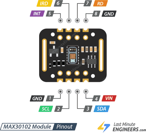
The pinout of this module is well explained in this online tutorial as follows:
- VIN is the power pin. You can connect it to 3.3V or 5V output from your Arduino.
- SCL is the I2C clock pin, connect to your Arduino’s I2C clock line.
- SDA is the I2C data pin, connect to your Arduino’s I2C data line.
- INT The MAX30102 can be programmed to generate an interrupt for each pulse. This line is open-drain, so it is pulled HIGH by the onboard resistor. When an interrupt occurs the INT pin goes LOW and stays LOW until the interrupt is cleared.
- IRD The MAX30102 integrates an LED driver to drive LED pulses for SpO2 and HR measurements. Use this if you want to drive the IR LED yourself, otherwise leave it unconnected.
- RD pin is similar to the IRD pin, but is used to drive the Red LED. If you don’t want to drive the red LED yourself, leave it unconnected.
- GND is the ground.
Because I was not using the red LED for oxygenation readings, I only connected the VIN, SCL, SDA and GND to my tree board.
Files for this week can be found here