HOW TO MAKE (ALMOST) ANYTHING
TIFFANY TSENG - FALL 2011
| 13 // FINAL PROJECT |
|
|
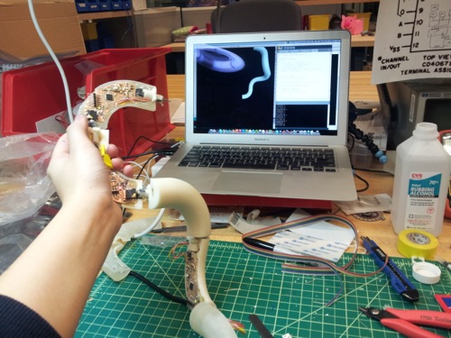
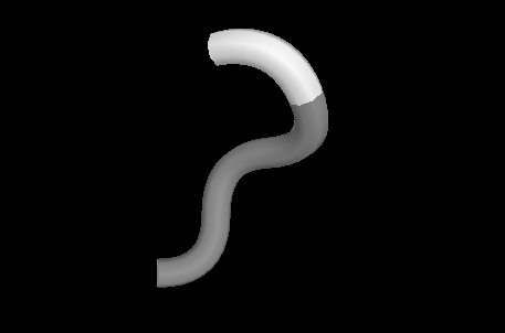
SELF-DOCUMENTING CONSTRUCTION KIT My final project is a self-documenting construction kit that builds a virtual model of an assembly of physical pieces.
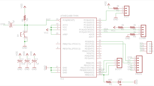
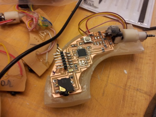
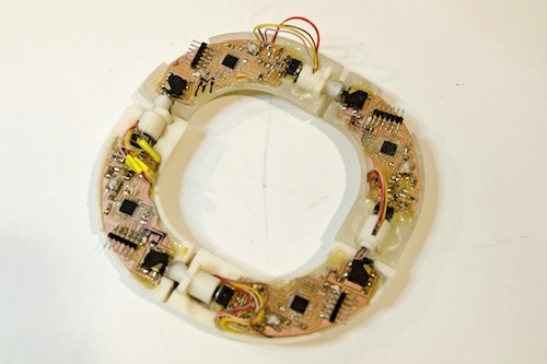
The idea behind this kit is to make it easier for people to share the designs they create using physical artifacts. By automatically creating a digital model, the kit enables people to capture their process of creating their design, share their designs easily on the web, and potentially rebuild another persons design by exploring the recorded design process. DESIGNING THE BOARDS The boards for my construction kit pieces are a modified Fabduino board. The pieces communicate via I2C, and I used a four pin 2.5mm audio connector to pass VCC, GND, SCL, and SDA lines between boards.
I had to create a custom part for my SMD audio jack. I followed this excellent tutorial on Instructables to help me through the process.
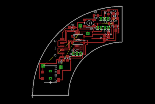
At some point, I got frustrated about trying to route connections between pieces within my constrained geometry, so I used a trick that Jennifer showed me; essentially, you add a pad and a hole by switching to the "bottom layer" while you're routing. For my audio jack, I have two pads that I used to solder jumper wires between the audio jack and the SDA and SCL lines of my microcontroller, which is on the opposite side of my board.
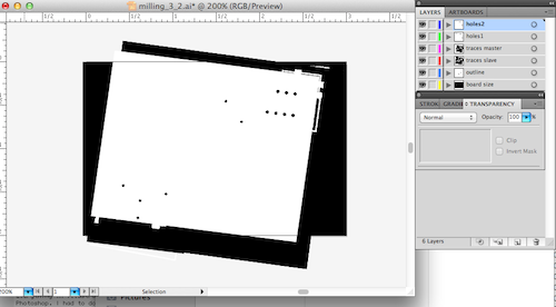
I found the process of preparing my image files to cut on the Modela to be extremely convoluted. I did everything in Illustrator since I'm more comfortable using it than Photoshop. I had to do this because in order to fit my shape on the standard 3x2 board, I had to rotate the image. Essentially what I did was I had a different layer for the traces, holes, and outline, and I changed the transparencies of the different layers to make sure the layers lined up.
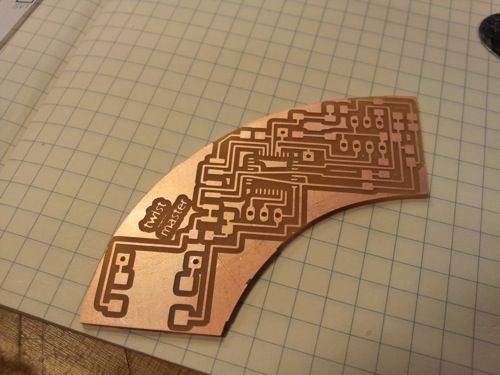
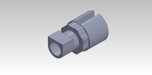
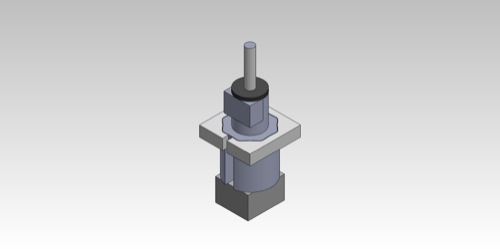
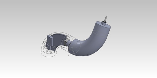
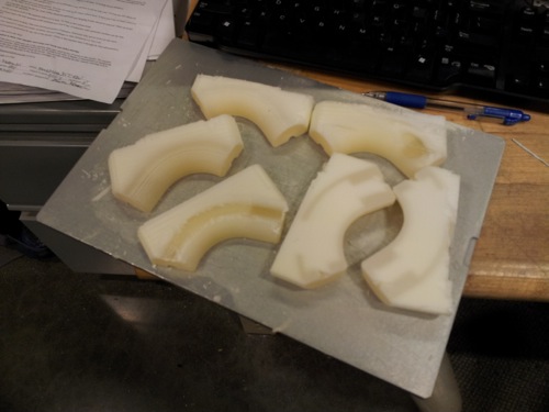
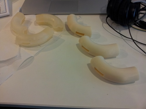
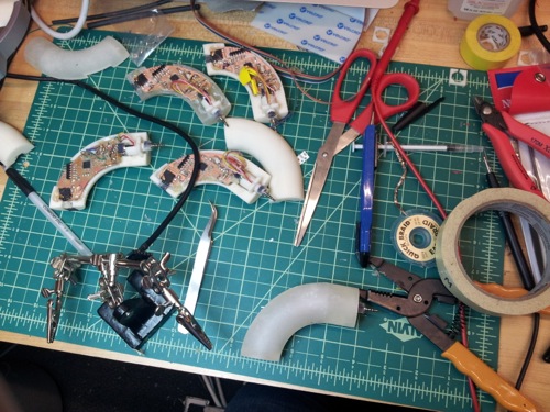
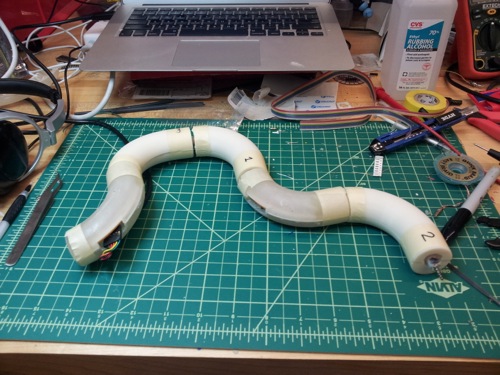
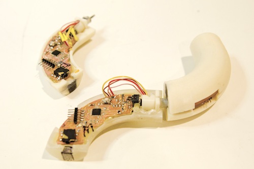
I ended up making 5 boards for 5 pieces. DESIGNING THE HOUSING To couple the potentiometer to the audio jack, I designed a custom coupling. I put a slot in the side of the coupling for the wires from the audio connector to come out. I also designed the coupling so that it would snap to particular positions so that the pieces would hold their form when assembled. The coupling has a flat side so that the pieces are keyed together and can thus only be connected one way.
Coupling and flexture for holding position
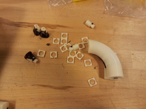
I printed the pieces on both the ABS and acrylic 3D printers. It was the first time I had printed on the acrylic printer. I thought that the acrylic pieces were nice because they were very easy to sand.
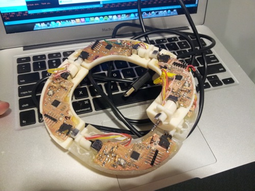
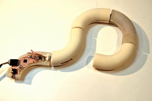
ASSEMBLING Putting together the boards was pretty straightforward but very time consuming, particularly because the connectors on the audio jack were very small and hard to solder too (without shorting the wires).
The boards worked well when hooked up together; yay!
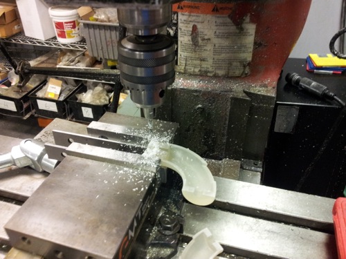
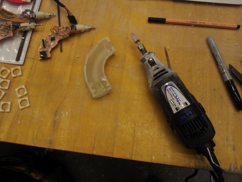
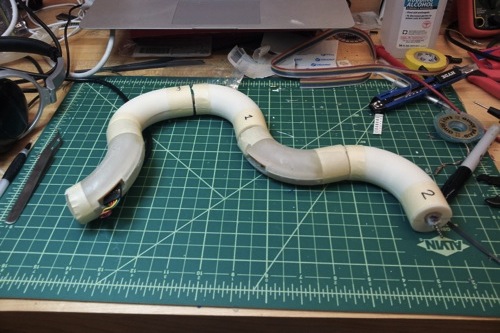
Assembling the boards in the physical housings was very very time consuming. I found that the boards didn't quite fit, so I had to sand down the edges. I used a dremel and mill heavily to open up extra slots in the housing. Unfortunately, the position of the audio jack varied from piece to piece based on how well the board was sanded to fit into the housing, which caused some problems with alignment when connecting the pieces. As a consequence, the pieces rotated without being keyed. I managed to fix this a little bit by using some hot glue along the edges to fill gaps.
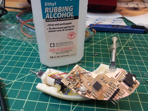
I used hot glue to attach the boards to the housing. To remove hot glue when I needed to, I applied some ethyl alcohol to the glue. It helps make the glue less sticky and easier to remove.
Of course, at 4AM the day the project was due, I realized that I had forgotten to put the essential pull up resistors to connect both the SDA and SCL lines to VCC on each board! I realized this when the boards seemed to mysteriously stop working when I touched the audio connector with my hand. Thankfully, the Responsive Environments group has a very well stocked selection of resistors. Thanks for their kind and unknowing donation of several 1.5K resistors.
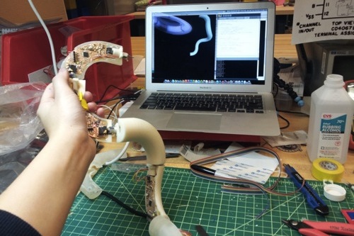
SOFTWARE DESIGN I reused a lot of my code from earlier assignments. It took me a while to figure out how to make sure the master maintained the order in which the pieces were connected. Many thanks to Sayamindu for helping me out with this! In the end, I used a combination of Arduino and Processing for my visualization. The piece number and potentiometer values are passed via serial communication.
FINAL THOUGHTS Unfortunately, some of my connections were flaky so my demo didn't quite work for the presentation. I worked a little more on it the day after, though, and found I had one loose cable in my master piece. After resoldering, I found it worked relatively well, although I still have the problem with the pieces not being keyed consistently. I plan to continue working on it, hopefully making the pieces much smaller and adding some more shapes to the kit! And finally, many, many thanks to all the people who helped me so much with this project, including David, Brian, Adam, Eric, Sayamindu, and all the awesome people in the class!
DESIGN FILES |