HOW TO MAKE (ALMOST) ANYTHING
TIFFANY TSENG - FALL 2011
| 08 // INPUT DEVICES |
|
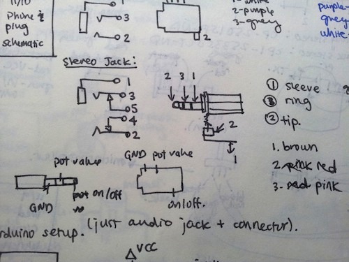
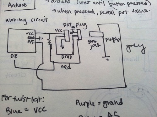
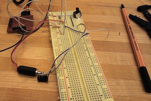
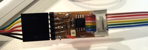
ASSIGNMENT Since I accidentally did this assignment two weeks ago, I decided to add on to the potentiometer circuit I had designed. I worked on coupling a potentiometer and a contact switch so that my pieces can sense both when they're connected and what their orientation is when connected. BREADBOARDING After brainstorming a few different ways to couple rotation and contact sensing, I went forward with an idea suggested by one of my office mates: using an audio jack to sense a connection. I found some stereo audio connectors and jacks in the CBA shop (Digikey PNs CP-250ISP-ND & CP1-2533SJCT-ND) and breadboarded the circuit. This took me a while and was a good refresher on circuits. Thanks to Brian for helping me get started.
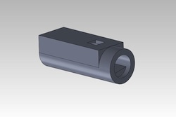
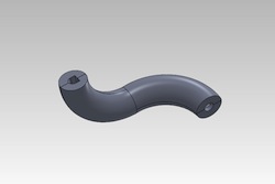
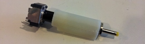
BUILDING THE PHYSICAL MODEL I designed a coupling for the audio plug and potentiometer in SolidWorks and keyed the model so that the coupling would pressfit into one end of the piece.
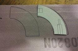
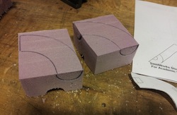
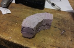
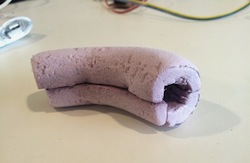
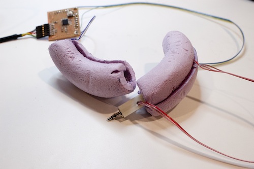
Wanting to prototype the physical pieces as quickly as possible, I decided to model them out of pink foam. To do this, I printed out a 1:1 model from SolidWorks and traced the image onto the foam. I then used a combination of the bandsaw, a hacksaw, and filing by hand to get the pieces.
I also 3D printed the coupling.
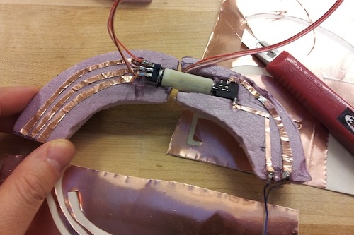
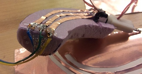
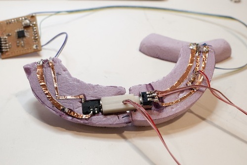
COMBINING THE PHYSICAL + DIGITAL Continuing with my goal of prototyping as rapidly as possible, I ended up cutting out my traces using an exacto blade. I originally tried cutting on the vinyl cutter, but I found that the dimensions on my pink foam pieces were not very accurate (as they were made by hand), so I needed to make adjustments. I hot glued the electronics to the piece as well to keep them in place.
Finally, I created a Processing program to visually signify when the pieces were connected and to show the potentiometer value when they were connected. The complete workflow is to upload the Arduino code to the board and then run Processing, which communicates with Arduino using serial communication.
The next step is to cut the size of these pieces...in half. Right now, they're way too big to design something useful with! LIGHT-SENSING BOARD I wanted to try working in C, so I milled the sample phototransistor board. Many thanks to Shahar for helping me figure out how to program the board! I typed the following into the terminal:
DESIGN FILES |