HOW TO MAKE (ALMOST) ANYTHING
TIFFANY TSENG - FALL 2011
| 04 // SHOPBOT |
 |
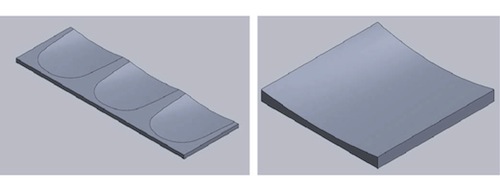
ASSIGNMENT This week's assignment was to make something big. I recently moved into an apartment in Central and needed to add more seating to our dining room table, so I decided to build a dining room bench. SURFACE MILLING My original idea was to surface the bench seat to make it more comfortable (think bus seats). I modeled the seat using SolidWorks and lofted cuts. I then made a scale model to cut during our first session with the ShopBot.
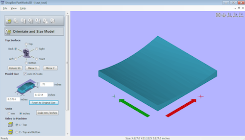
I exported the SolidWorks part as a STL file and imported it into PartWorks 3D. I needed to change the orientation of the model to "back" so that it the z access was on the right plane (see image below). Also, the thickness of the part was incorrect, so I set this to 0.75 inches.
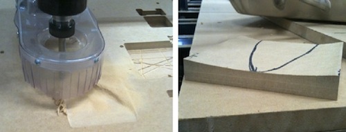
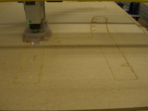
I used a 1/2" ballnose endmill with a spindle speed of 12000 rpm, a feed rate of 120 in/min, and a plunge rate of 30 in/min. The stepover was set to 25%. We ended up just doing a finishing toolpath with a pass depth of 0.25". For the cut out path, we set "material to leave" to -0.1.
DESIGNING THE BENCH I had trouble settling in on an idea for the bench and tried modeling a lot of different ideas. Generally, I wanted to gain more experience with surfacing in SolidWorks and ended up learning a lot about designing multi-body parts (thanks to some help from Yoav)!
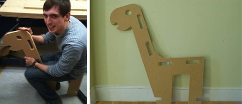
I decided to try cutting the "dino" bench and did a lot of test cuts before cutting out one of the side panels. But even after the tests, the slots were really oversized, and I found that the bench was a few inches too low.
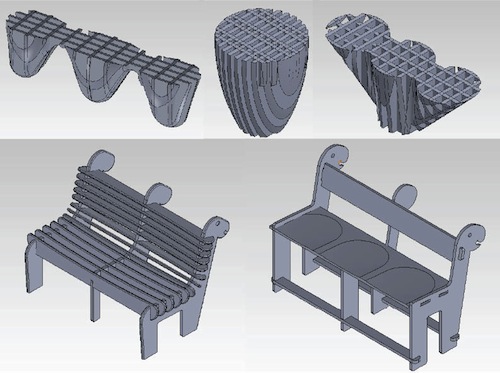
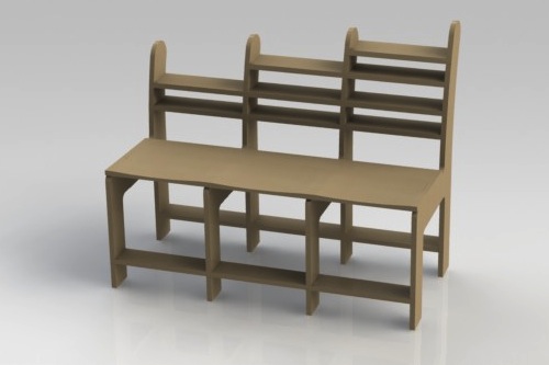
After the failed attempt at making the dino bench, I decided to re-design the bench and came up with a new design:
Here's how I designed the model in SolidWorks: |


. Make sure to only select one body when you perform the cut!")


|
|
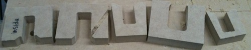
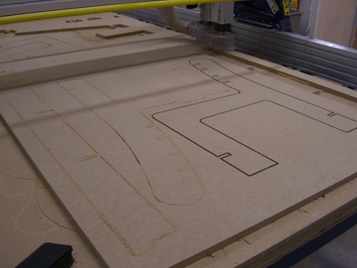
CUTTING ON THE SHOPBOT Cutting all of the pieces took around 6 hours. I used the MDF that was available in the architecture shop. I attempted to use PartWorks 3D for surfacing but found that the entire seat would take about two hours to cut, and my partner was already nice enough to stay until 3 AM, so I decided not to surface mill the seat.
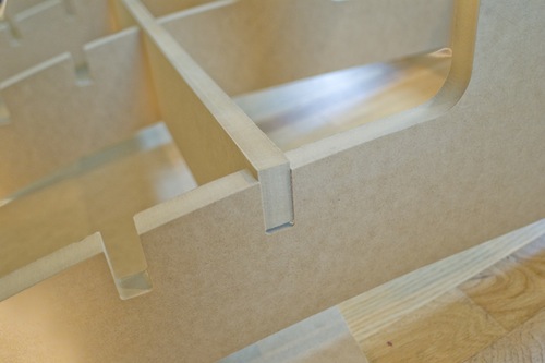
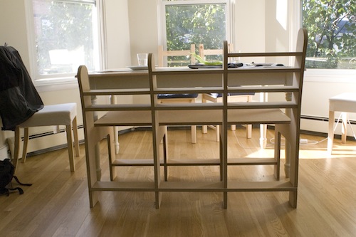
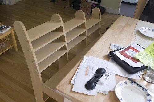
The back support for the bench also wasn't surface milled, resulting in some pieces that stick out of the bench. Things I learned from using the ShopBot:
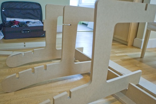
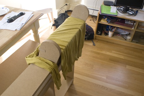
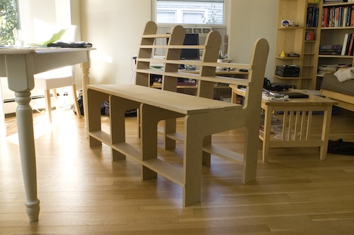
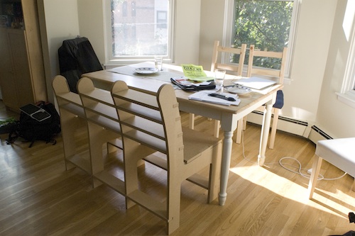
ASSEMBLING THE BENCH
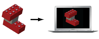
DESIGN FILES UPDATED FINAL PROJECT PROPOSAL For my final project, I'd like to make self-documenting LEGO bricks. This would involve adding electronics to existing LEGO bricks to make them capable of sensing their connections. The connected bricks would form a CAD model in real-time so that people can share their designs with others easily without having to create a separate digital model from scratch.
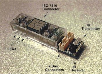
Prior Work There are many examples of smart building blocks, including the following:
System Components
Questions / Tasks
|