How To Make (Almost) Anything - 3D Scanning & Printing

Massachusetts Institute of Technology
MAS 863 How To Make (Almost) Anything | Fall 2011

Vernelle Noel - vernelle@mit.edu  | 


Home

Week 1 - Final Design Proposal

Week 2 - Make Press Fit Kit

Week 3 : Make FabISP in-circuit programmer

Week 4.1 : Make Something BIG

Week 4.2 : Final Project Review

Week 5 : Molding & Casting

Week 6 : Embedded programming

Week 7 : 3D scanning and printing

Week 8 : Input devices

Week 9 : Output devices

Week 10: Machine design & Final Project Revisted

Week 11: Networking and communications

Week 12: Final presentation

Helpful list of programs


Website >>

Blog >>

Flickr >>

Youtube >>


"3D Scanning & Printing"

This week our assignment was to "3D scan an object (extra credit: make the scanner), and
design and 3D print an object (small, few cm) (extra credit: edit and print an object that you scanned).

This week we learned to use the Minolta for 3D Scanning. I did not have much interesting things to scan. I wanted to scan a brass horse that was given to me by my friend John in India. We were told that black and shiny objects do not do too well with 3D scanning, but I wanted to try it anyway.

Here is my procedure for using the Minolta:

Starting
Open the Geomatic Program on the pc. You will be asked if you would like to calibrate the scanner, for now we were told to choose, NO.

Along the left hand side of the screen is the main dialogue box for options w.r.t scanning. Check "Show Live Image". In the window that opens check "Enable Streaming video."

Place the calibrating screen on the turntable to focus the lens. Adjust the scanner using the two cranks located below the scanner housing or moving it forward or backward. This will depend on your object size and what you want.

Once the object and focus are positioned, click "Update the Color image" in the view window. You are looking here for good focus. If the focus is not so good you can uncheck "Autofocus" and change the distance between the lens and the object. Click "Update the Color Image" again. Repeat as needed until focus is fairly sharp.

2 Calibration:

Next, calibrate the scanner. Placing the calibration sheet on the turntable so that the stubs on the bottom fit into the grooves on the turntable stage. This should be placed so that the center of the stage is visible to the scanner. Click "Update Color Image" If the focus looks good, click on "Update Range and Color" in the same window. What you are looking for here is a color mapping of a good median range (orange-yellow-green)... See Image #2. If so, click "Calibrate Axis" near the bottom of the left hand panel.

3. Scanning:

Place your object on the turntable so that its center lines up almost exactly with the center of the turntable. Select a rotation increment enough so that you can get most of the object scanned but no so much that too much data is generated. 45 or 90 degree steps works fine. Check "Show current scan only" and press "Scan".The result of the scan can be seen in the large window. If it looks ok, click next. Rotate the scan if you're unsure of the results, as sometimes not all of the information is visible in the unrotated view.

The software freezes sometimes so please remember to save!

4 Merging:

Remove "noise" and unwanted data by dragging a box around the "noise" and press delete. Rotate the image as needed to clean the image. Once the object is reasonably clean select "points" > "merge".

Now select "Polygons" > "Fill Holes". DO NOT "Fill All."

5. Editing:

Most likely your scan will have some holes in it. If the holes are small select "Polygons" > "Fill holes". DO NOT "Fill All."

CHoose the areas with the holes and it should fill it in quite nicely, and sometimes even fill in and smooth out the print/ color.

Click here for Minolta procedure >>

This week I also milled and stuffed my Fabduino board. I will program it this week.

Resources:
1. Txt file to myself on procedure for uploading material to site

Acknowledgements:
John for always being a great teacher and supporterl.

Tom for being one of the coolest guys ever!

Links:

Website: http://www.vernellenoel.com/
Blog: http://thinkinginsomniac.wordpress.com
Flickr: http://www.flickr.com/photos/thinkinginsomniac/


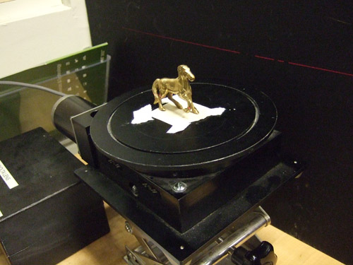
Placement of brass horse on the turntable


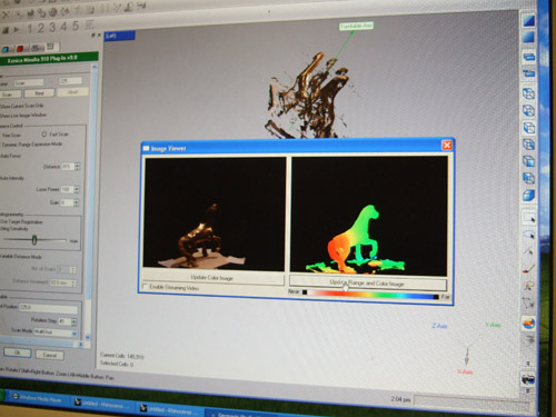
Screenshot of "color imaging" of brass horse
 
 
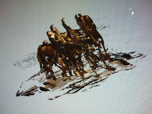
This is what occurs when your object is not EXACTLY lined up with the center of the turntable
 
vernelle-noel-AIM_design_competition_china
 
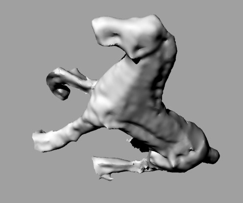
After trying again to match centers as best as I could, my horse came out, ok...
 
vernelle-noel-AIM_design_competition_china
 
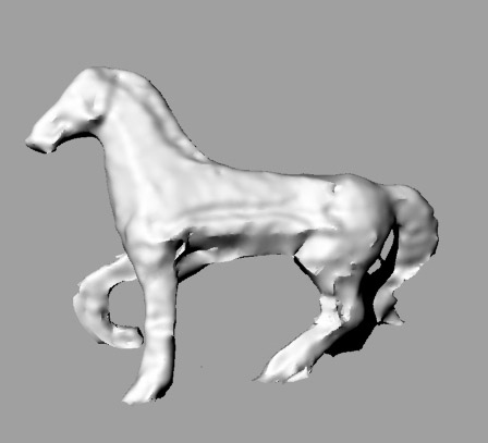
3D Scan of brass horse
 
vernelle-noel-AIM_design_competition_china
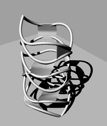
Rhino model of ring I designed to 3D Print
 
 
vernelle-noel-AIM_design_competition_china
 
vernelle-noel-AIM_design_competition_china
 
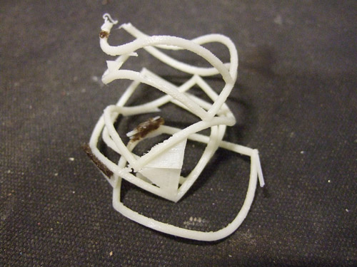
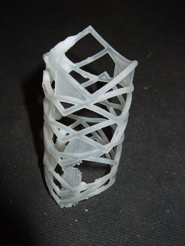
Image of object after printing. It didn't make it through the wash...so I had to make certain parts larger.
 
vernelle-noel-AIM_design_competition_china
 

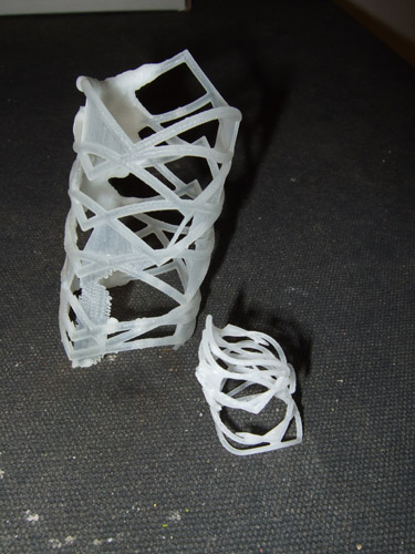
Another try at 3D print with larger elements... still not up to par

 
vernelle-noel-AIM_design_competition_china
 
 
vernelle-noel-AIM_design_competition_china
 
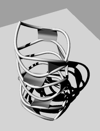
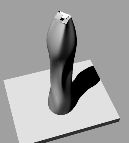
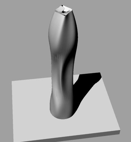
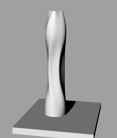
Vase/ volume form designed in Rhino for 3D Print
 
vernelle-noel-AIM_design_competition_china
 
vernelle-noel-AIM_design_competition_china
 
vernelle-noel-AIM_design_competition_china
 
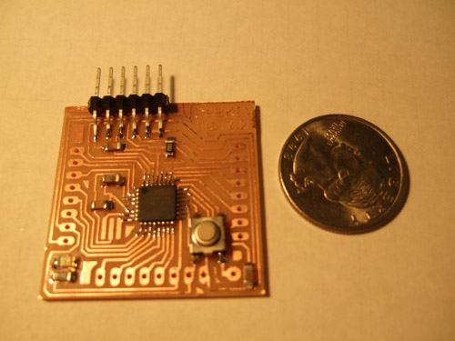
I milled and soldered my Fabuino Board... Looking forward to programming it.


<<<Previous..................Next >>>


Home | Blog | Flickr  | vernellenoel.com