Massachusetts Institute of Technology
MAS 863 How To Make (Almost) Anything | Fall 2011
Vernelle Noel - vernelle@mit.edu |
|
Week 1 - Final Design Proposal Week 2 - Make Press Fit Kit Week 3 : Make FabISP in-circuit programmer Week 4.1 : Make Something BIG Week 4.2 : Final Project Review Week 5 : Molding & Casting Week 6 : Embedded programming |
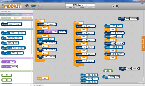
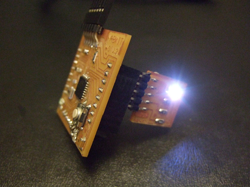
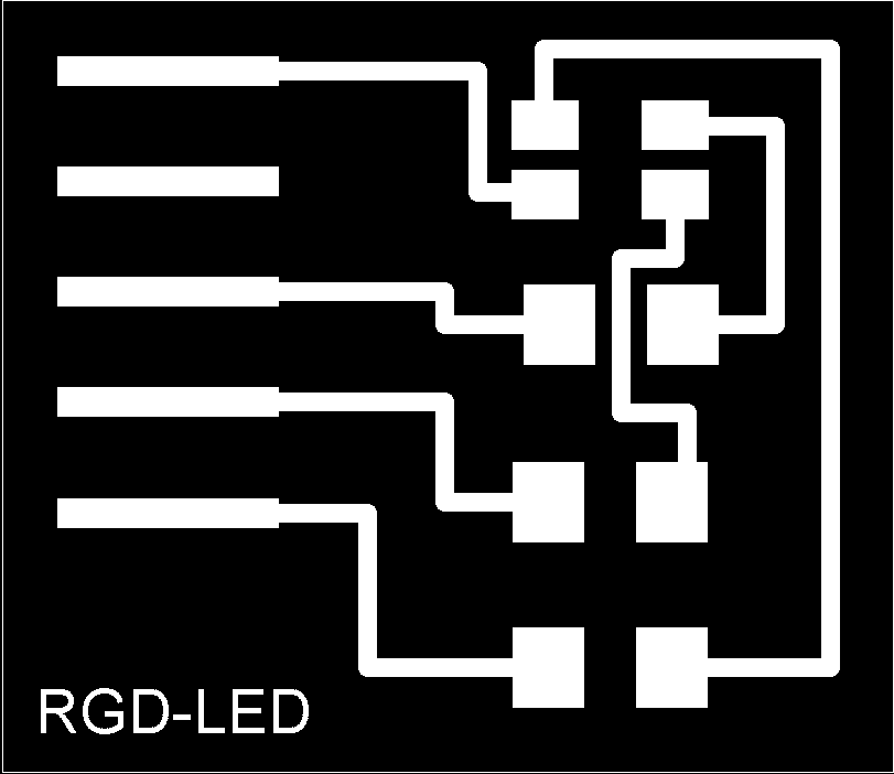
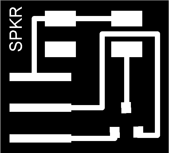
"Ouput Devices" This week our assignment was to "add an output device to a microcontroller board and program it to do something." I decided to do an RGB LED and SPEAKER for output devices. I did four (4) boards; two to be programmed with C, and the other two to be programmed with ModKit. Remember if you are using ModKit, you have to redesign your board. Thanks to Yoav's help I was able to get some guidance on redesigning my board with Eagle. Everything went fine with milling and soldering my components on all four (4) PCB boards. With Adam Setapen's help I programmed 2 of the boards using C from the command line. We tried to figure out how to use WinAVR... but that was unsuccessful.. so he just showed me using the command line. Both boards worked... the RGB Led, and the Speaker. I then tried to program my boards with ModKit.. I got the RGB Led board to run very well. I experimented with the codes... and they were fine. I did not have the same success with the speaker board though. Why, I don't know as yet. I will find out. Lessons Learned: 1. Modkit is a great place to start but assistance on using the program is still needed.. 2. Mark your ground pins on your connections. Resources: 2. RGB Eagle files (board). 3. Speaker files (board). 4. RGB Led Board trace and outline. 5. Speaker Board trace and outline. Links: |
|||||||||
 |
|||||||||
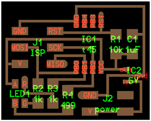
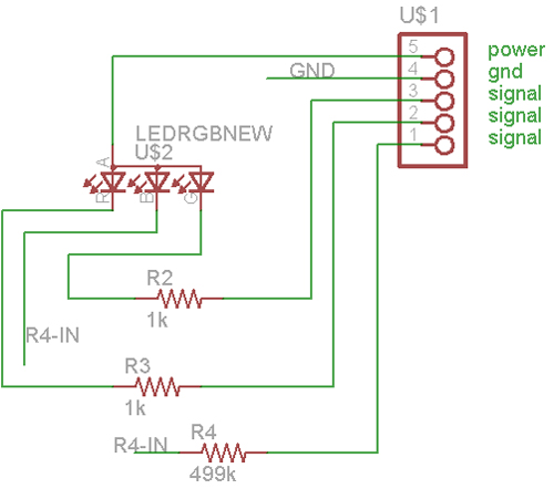
| Layout for RGB Led Board | |||||||||
 |
|||||||||
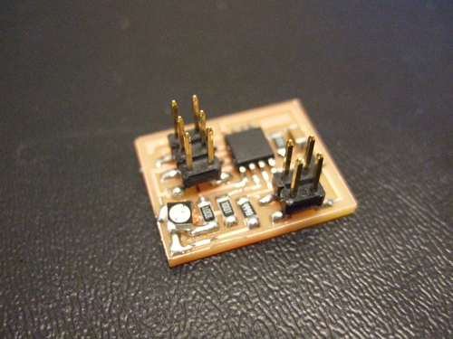
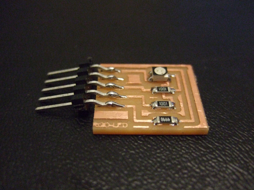
| Photo of RGB Led Board | |||||||||
 |
|||||||||
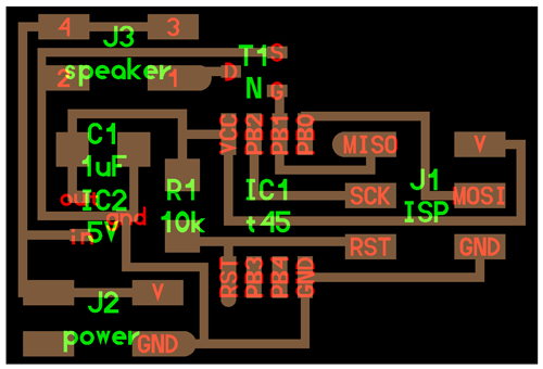
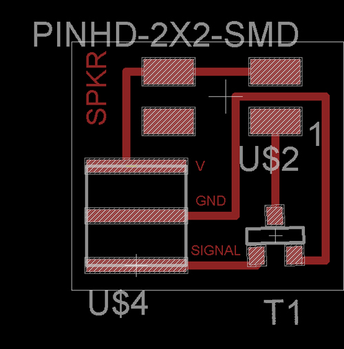
| Layout for Speaker Board | |||||||||
 |
|||||||||
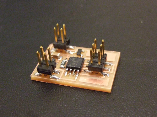
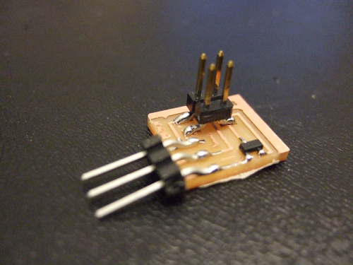
| Photo of Speaker Board | |||||||||
Video of speaker making sounds ;-) |
|||||||||
 |
|||||||||
| Eagle schematic of RGB board for Fabduino | |||||||||
 |
|||||||||
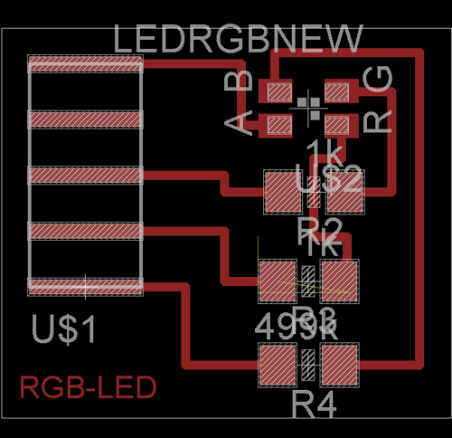
| Eagle board of RGB Led board for Fabduino | |||||||||
 |
|||||||||
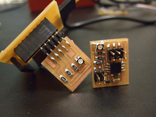
| Photo of atom board with RGB Led to be used with Fabduino | |||||||||
 |
|||||||||
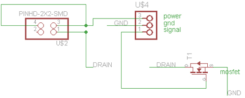
| Eagle schematic of speaker board for Fabduino | |||||||||
 |
|||||||||
| Eagle board of speaker board to be used with Fabduino | |||||||||
 |
|||||||||
Photo of atom board for speaker to be used with Fabduino |
|||||||||
 |
|||||||||
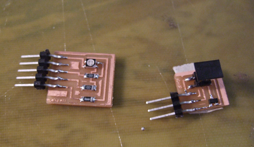
| Photo of both boards | |||||||||
 |
|||||||||
| Comparison of components on atom board versus USBTiny board | |||||||||
 |
|||||||||
| Screen shot of Modkit codes installed on board | |||||||||
 |
|||||||||
 |
|||||||||
 |
|||||||||
 |
|||||||||
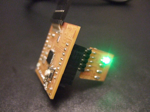
| Video of RGB Led working | |||||||||
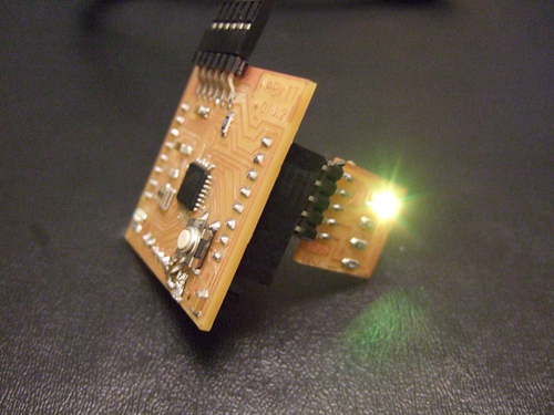
| Video of RGB Led working | |||||||||
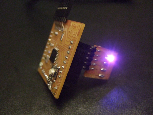
| Video of RGB Led working | |||||||||
<<<Previous..................Next >>>
|
|||||||||
Home | Blog | Flickr | vernellenoel.com