Massachusetts Institute of Technology
MAS 863 How To Make (Almost) Anything | Fall 2011
Vernelle Noel - vernelle@mit.edu |
|
Week 1 - Final Design Proposal Week 2 - Make Press Fit Kit Week 3 : Make FabISP in-circuit programmer Week 4.1 : Make Something BIG Week 4.2 : Final Project Review Week 5 : Molding & Casting Week 6 : Embedded programming |
"Embedded Programming" This week our assignment was "Embedded Programming," to (at least) add a button and LED (with current-limiting resistor) to the echo hello-world board, check the design rules, and make it. This week I learned Eagle, which I found to be intuitive. Great tutorial and explanation. My main notes from the tutorial are as follows: The ISP Header is how we program the microprocessor. The FTDI Header is how you communicate with the PCB Board. The Microprocessor (in this case, the ATTiny 44) is the brain. We will be using a 20MHz resonator which speeds up the clock for the ATTiny so that it can do operations faster. Some important commands to remember from Eagle are: NET - command to make logical connections in schematic ROUTE - converts unrouted connections into routed wires RIP - Changes routed wires into airwires. GROUP ADD - to pull up the Library Dialogue and choose components. LABEL - Attaches text labels to buses and nets JUNCTIONS - Places a dot at intersecting nets ERC (Electronic Rules Check) - This command is used to test schematics for electrical errors. It detects inconsistencies between the implicit power and supply pins in the schematic and the actual signal connections in the board. DRC (Design Rules Check) - Checks design rules. After designing my board, I exported the image (after removing certain layers) to a png file (monochrome), with a resolution of 1000 dpi. This file would be used (Fab Module) for the milling of the board as seen in photos. Resources: 2. Schematic (Eagle) 3. PNG of board 4. Code for LED to blink when pushed 5. Txt file to myself on procedure for uploading material to site This week I was introduced to Arduino and Modkit. I am not a programmer, therefore the visual logic of Modkit excited me a lot!!! I will be using Modkit in the future. Thank you so much Ed for introducing this to us! Whew! Acknowledgements: Ed Baafi for his ModKit introduction. Dan & Toni for your great "modela karma" as Toni would say. Alan, Albert, and Marshall - it's always a great thing when you get to know your classmates a little better. ;-). Brian Mayton for all your programming help. You are a great teacher. Links: Website: http://www.vernellenoel.com/ |
 |
||||||||
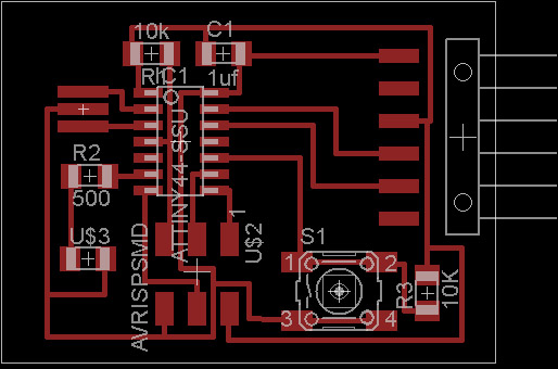
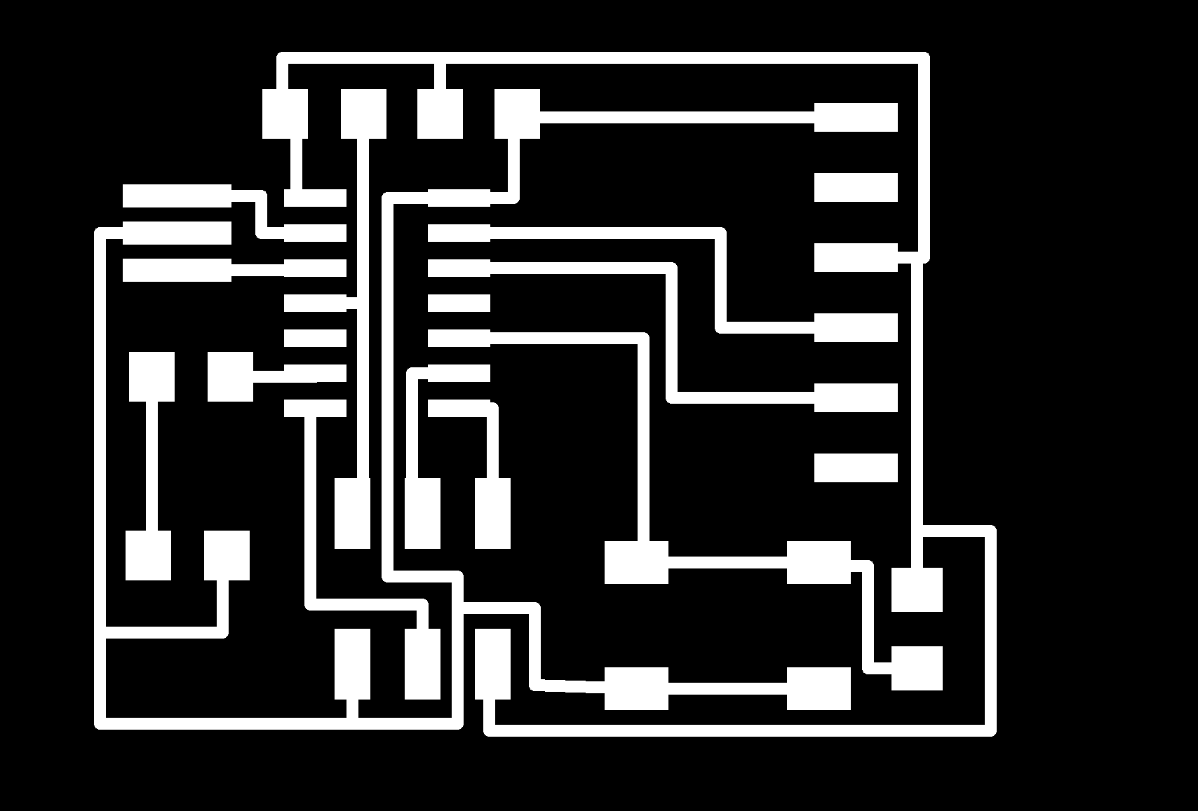
Board I designed with a switch and an LED |
|||||||||
 |
|||||||||
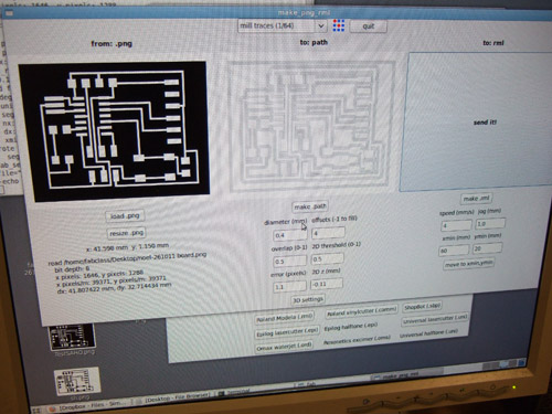
Screenshot of the loaded png which makes the path and the rml for milling |
|||||||||
 |
|||||||||
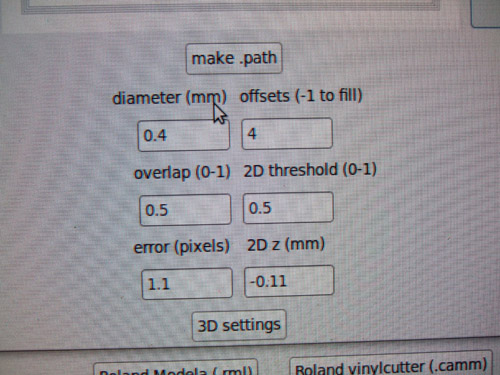
After milling the first round, some traces were not as clean as they should be, so I ran it again. Adding .001mm to the previous depth I milled at, -0.10mm became -0.11mm. |
|||||||||
 |
|||||||||
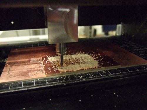
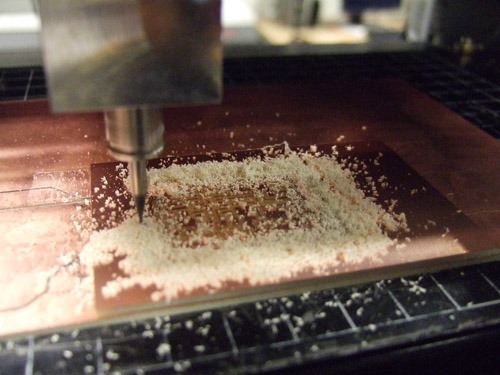
Modela milling out the traces using 1/64" bit |
|||||||||
 |
|||||||||
Modela cutting outline of board using 1/32" bit |
|||||||||
 |
|||||||||
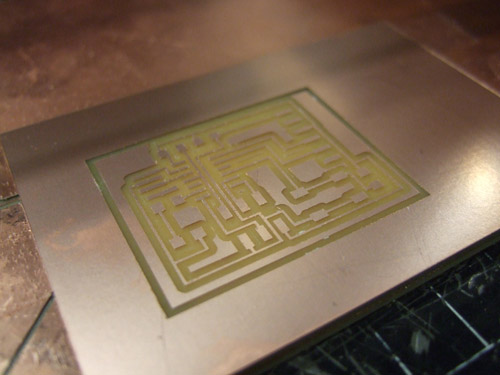
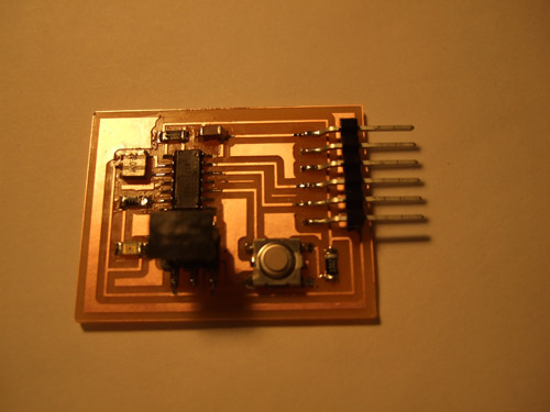
| Board after it was milled and cleaned | |||||||||
 |
|||||||||
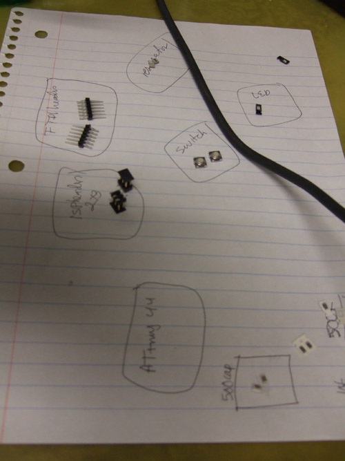
My components to "stuff" (solder) unto my board |
|||||||||
 |
|||||||||
Board before soldering the FTDI Header. |
|||||||||
 |
|||||||||
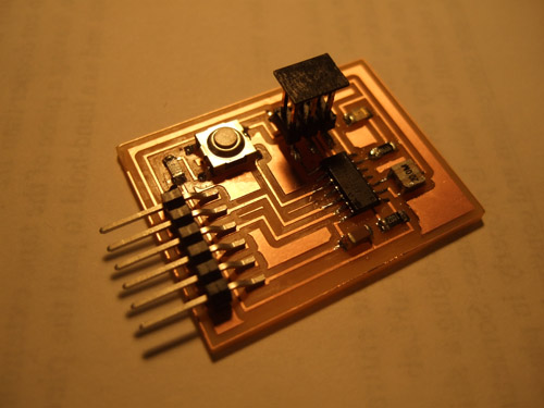
| Soldering complete... now to program the board. Remember SHINY IS GOOD! | |||||||||
<<<Previous..................Next >>>
|
|||||||||
Home | Blog | Flickr | vernellenoel.com