Massachusetts Institute of Technology
MAS 863 How To Make (Almost) Anything | Fall 2011
Vernelle Noel - vernelle@mit.edu |
|
Week 1 - Final Design Proposal Week 2 - Make Press Fit Kit Week 3 : Make FabISP in-circuit programmer Week 4.1 : Make Something BIG Week 4.2 : Final Project Review Week 5 : Molding & Casting Week 6 : Embedded programming |
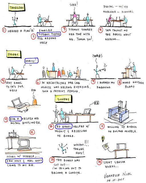
"Input Devices" This week our assignment was to "measure something: add a sensor to a microcontroller board and read it." First of all I would like to thank: - Moritz Kassner- Rob Hemsley - Ed Baafi - Tiffany Tseng, and - Dan Novy for their time, assistance, and being there when I asked for help. This would be impossible without you. ;-). I decided to do light and sound for input for my devices this semester. So I built two (2) boards. My goal was to program my boards with ModKit, a graphical programming environment for microcontrollers. I have high hopes for this program as I am no programmer; and C and Arduino are difficult to write if you have never done programming before. The sooner you get acquainted with ModKit, or find someone committed to helping you learn another programming environment, the better... otherwise, you will be in trouble! After building the two boards, I had to make another Fabkit/ Fabduino Board because it got burned. Burning Bootloader: When all boards were set and ready, I now had to burn the bootloader onto the Fabduino using the USBTiny. The burn bootloader command configures the fuses of ATmega168 for an internal 8 MHz clock. Be sure to keep the button pushed down on your Fabduino while the bootloader is burning. It will blink several times and tell you when the bootloader has finished loading. Testing: To test the correctness of my Fabduino, I used the Arduino "Blink" code... and it worked! The Fabduino board already has its microprocessor (ATmega168), and what I would need to do is design another board without the microprocessor and its supporting components, and design a board only with those needed to run the phototransistor (and/ or the microphone). Yikes!!! Ed explained to me how the designing of these separate boards to plug into the Fabduino should work. Mighty helpful. Now all I need to do is learn electrical design I guess... I'll try bit by bit. We made "Mac Gyver" looking contraptions to test the components and connections needed for the light sensor to work. Using Modkit it worked!!! then the board was designed in Eagle. Milling and Stuffing: After exporting the design from Eagle to png files I went to mill them on the Roland Modella. That was another issue, but in the end, with Novy's help, I made my boards and soldered my components. Programming with Modkit & Arduino: When I got home I checked and programmed my boards using Modkit and Arduino and they both worked. See images for the results. I still have to design the layout for the microphone to be able to use it with the Fabduino. I hope to get the time to try that because I know it will help me. Lessons Learned: 1. Modkit is a great place to start for non-programmers. 2. Be sure you have someone to count on to help you when you need it... and do the same for someone else. 3. Have a Plan B, and C. Resources: 2. Eagle files (board) and (schematics). Links: |
 |
||||||||
| Thank you!!! | |||||||||
 |
|||||||||
| Burned Fabduino board on right, I had to mill and make another one. :-( | |||||||||
 |
|||||||||
| Built the board with microphone to measure sound | |||||||||
 |
|||||||||
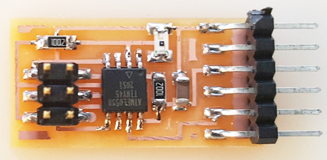
Built board with phototransistor to measure the quantity of light entering it |
|||||||||
 |
|||||||||
FabISP board w/ USBTiny used to burn the bootloader onto the Fabduino |
|||||||||
 |
|||||||||
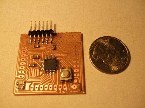
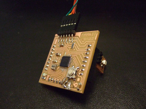
| Fabduino (without female headers) | |||||||||
 |
|||||||||
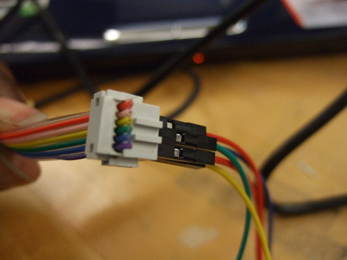
| Wire connectors used to connect the ISP pins (5V, GND, SCK, MISO, and MOSI) from the FabISP to the Fabkit/Fabduino board | |||||||||
 |
|||||||||
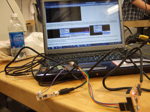
Connections from FabISP (V, GND, SCK, MISO, and MOSI) going to... |
|||||||||
 |
|||||||||
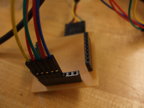
... corresponding pins (V, GND, SCK, MISO, and MOSI) pins on Fabduino board |
|||||||||
 |
|||||||||
| Bootloader burning onto Fabduino | |||||||||
 |
|||||||||
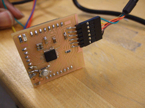
| Testing: Loading of Arduino "Blink" program onto board (light off) | |||||||||
 |
|||||||||
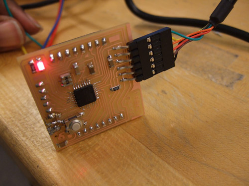
| Light on!!! Woohoo!!!!! It works!!!! | |||||||||
 |
|||||||||
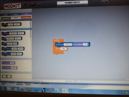
| Using Modkit for programming functions onto boards (graphical programming environment for microcontrollers) | |||||||||
 |
|||||||||
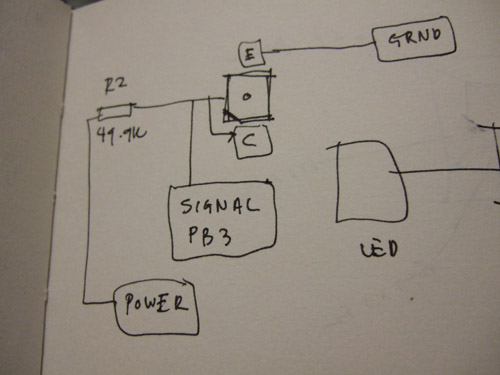
| Redesign/ Sketch of new circuit board with phototransistor to plug into Fabduino | |||||||||
 |
|||||||||
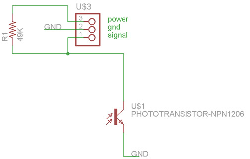
| Schematic Design of circuit board in Eagle | |||||||||
 |
|||||||||
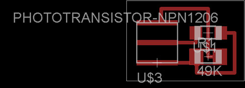
| Board layout in Eagle | |||||||||
 |
|||||||||
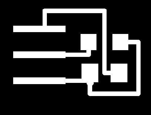
| Traces for milling of board on Roland Modela | |||||||||
 |
|||||||||
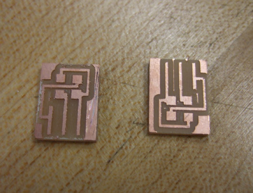
| Boards after milling and cutting. Be aware of png files and the Fab Module... things act funny and waste time for no apparent reason!! Add an hour or two to your planned time to allow for obstacles like this. | |||||||||
 |
|||||||||
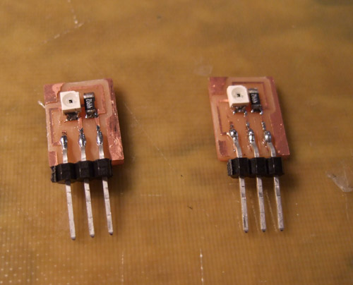
| Circuit boards after soldering components | |||||||||
 |
|||||||||
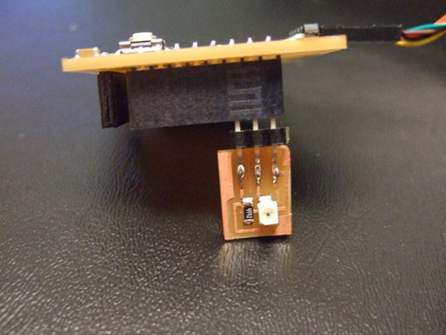
| Fabkit/ Fabduino board with phototransistor circuit board plugged in to it | |||||||||
 |
|||||||||
| Circuit board with phototransistor and resistor | |||||||||
 |
|||||||||
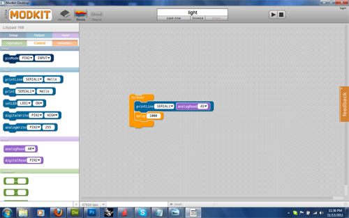
| Screenshot of Modkit | |||||||||
 |
|||||||||
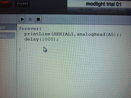
| Code resulting from graphic window | |||||||||
 |
|||||||||
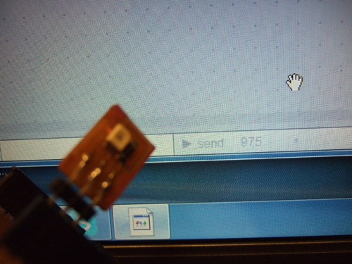
| Testing of sensor with Modkit: Reading of 975 when sensor is exposed to normal light | |||||||||
 |
|||||||||
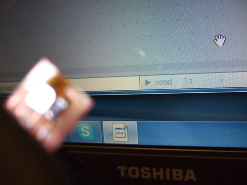
| Testing of sensor with Modkit: : Reading of 31 when exposed to bright light | |||||||||
 |
|||||||||
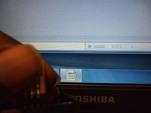
| Testing of sensor with Modkit: : Reading of 1023 when in darkness | |||||||||
 |
|||||||||
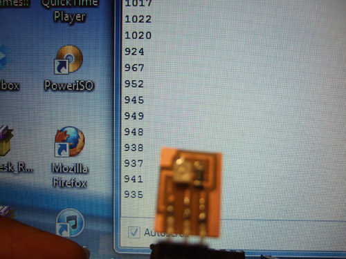
| Testing of sensor with Arduino: Reading in 900's when exposed to normal light | |||||||||
 |
|||||||||
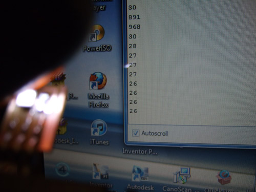
| Testing of sensor with Arduino: Reading in 20's when exposed to bright light | |||||||||
 |
|||||||||
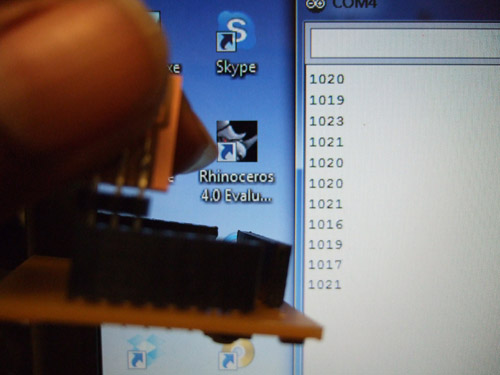
| Testing of sensor with Arduino: Reading in 1000's when in darkness | |||||||||
<<<Previous..................Next >>>
|
|||||||||
Home | Blog | Flickr | vernellenoel.com