Our assignment for the week was to redraw the echo hello-world board, add a button and LED, and make it.
REDRAWING THE BOARD:
I've never designed or drawn electronics before, but I found the process of copying a pre-existing design and adding
a couple elements to it quite helpful as an introduction. Eagle is a relatively intuitive program to use, especially if
you are familiar with command prompt/cad drawing. In my first attempt at drawing the board, I didn't know about the "name" and "label"
commands, so I was just drawing every connection between every component and it got to be quite messy and confusing. But, once
I learned about naming (name where you want to connect) and labeling (show the name of where you are connecting), it was much
more organized and certainly a clearer representation of what was going on. This was also a much better way to ensure everything
was connected (as opposed to drawing the wires between everything and then discovering some things are just touching, but not
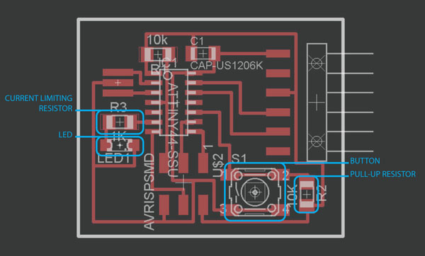
connected). Next, in the board view, I was able to layout my components by mimicking the example and then route the traces between
them. I found this process a little tricky. I liked that the program knew what was supposed to be connected to what based on the schematic, but
the grid alignment and order in which you connect things threw me off a little. Now that the base design was done, I had to add a
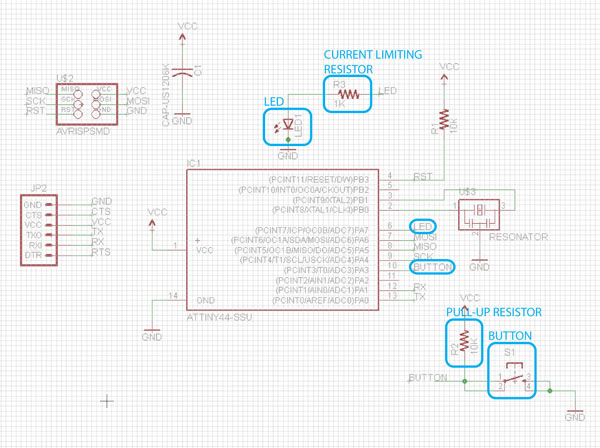
button and an LED. The clearly orgainized schematic view was helpful for this as I could easily see which pins were
open (referencing the board layout) and add my button and LED without much confusion. As per Neil's explanation last week, I paired
the LED with a 1K resistor to limit the current (and prevent it from blowing up). And I paired the button with a 10K pull-up resistor,
which pulls the voltage high until the button is engaged (at which point it goes to low voltage, or ground).
EAGLE SCHEMATIC:
EAGLE BOARD:
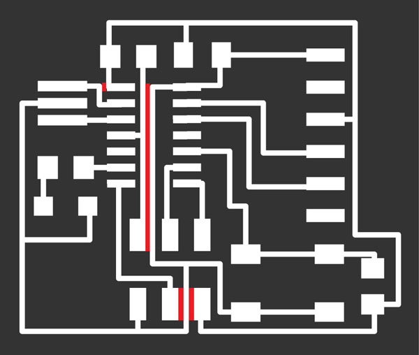
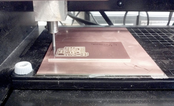
MILLING ON THE ROLAND MODELA:
I encountered a couple issues in the milling process. First, when I
simulated the mill paths, I realized that the spacing between some of the traces was too tight. So, I went back and
edited my PNG in Photoshop to increase it slightly. The second issue was the 1/64" end mill once again wasn't cutting to the
right depth, despite careful zero-ing and increasing the cut depth. So, I decided to replace the end mill and it worked
like a charm. I'm not sure why the 1/64" end mills seem to be getting dull so easily...
SPACING ISSUES:
MILLING SUCCESS:
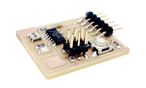
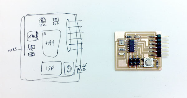
STUFFING:
Stuffing went pretty smoothly. I was definitely more confident about my soldering skills this time around. I just
hope everything is properly soldered for when we program the boards!
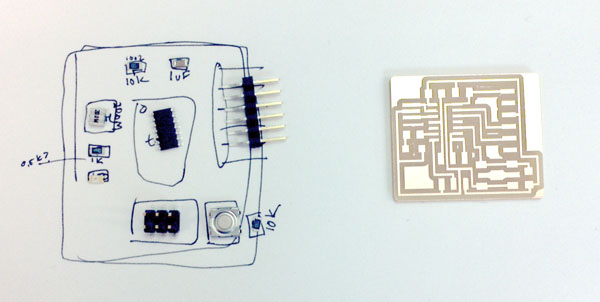
UNSTUFFED:
STUFFED: