The creation of a milled circuit board with soldered components to assist in programming arduinos.
Design
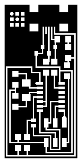
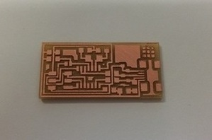
The design of the circuit board was provided to us as .pngs generated from Eagle, a Printed Circuit Board (PCB) software design tool. It consisted of traces for both the interior and exterior part of the board. The purpose of the project was to gain comfort with a mill and produce a board that will be used later in the semester. The milling of the board was done using a Modelo mill and the board was stuffed by hand.

Milling
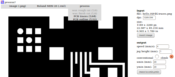
1. Before starting, ensure that you have the Modela instructions, mod_defaults, and both the trace and contour on the Ubuntu shop computer. 2. Open a new terminal, and follow the Modela instruction readme file, until your terminal says "listening to server." Minimize the terminal window and navigate to mod.cba.mit.edu. 3. In the module, lead the mod_defaults file. If successful, you should see a "read mod_defaults" prompt appear. 4. Pick "image (.png)" for the first column, "Roland MDX-30 (.rml)" for the second, and "PCB traces (1/64)" for the third column. The circuit board image should load and the right side parameters should automatically populate.
5. As a sanity check, input a xmin and a ymin and click "move to xmin,ymin." The Modelo should move the tool to the new origin you specified. If it moved, click the View button on the Modelo to make the base area accessible. 6. Obtain a copper plate and use double sided scotch tape to secure the plate to the base. Try and leave a little bit sticking out; It will make removing the plate later easier. Be sure not to overlap the scotch tape! Press down firmly. Press View on the Modelo to return it to the xmin and ymin coordinates.
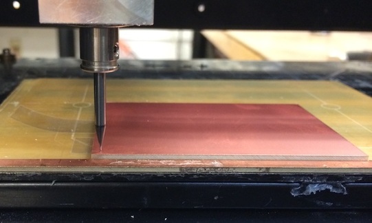
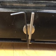
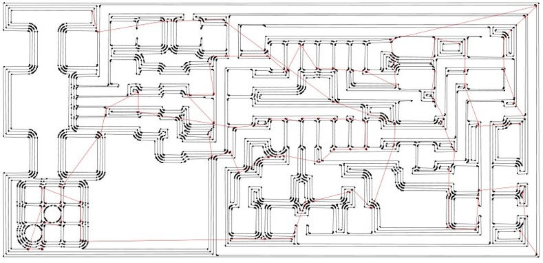
7. Use the Up/Down buttons on the Modelo to control the tool height. Manually adjust xmin, ymin to get tool to the bottom left of a board. You should be able to fit three boards on one piece of copper! Write down the xmin, ymin coordinates! You will need them later. 8. Place a 1/64 end mill into the Modela tool by loosening both screws on the tool using an allen wrench. Place the end mill almost all the way up inside the tool. Tighten both nuts on tool (do not overtighten!). 9. Using the Up/Down keys on the Modelo, lower the tool. Given that you placed the end mill almost all the way up, you should not be able to touch the copper. Instead, leave about a cm gap from the lowest the tool will go. While holding the end mill with one hand, loosen the nuts and gently place the end mill on the copper. 10. Finally, hold down the end mill onto the copper (so it does not move) and re-tighten the nuts. For security, press the down button on the Modelo once or twice to ensure penetration. 11. Now, go back to the module on the lab computer. The png should still be loaded. Click "Calculate path." You should see a stencil image of where the Modelo will mill. Black lines and arrows indicate the direction the board will be milled. Red lines indicate when the tool is raised. Check for any discontinuities or clearly visible milling offenders. Else, ensure the Modelo machine is clear, the copper plate is ready, and press "Send Path."
12. When completed, press View Mode on the Modelo, use a shopvac to clean the area, and ensure the piece is okay. 13. IMPORTANT: If you are going to continue and make the exterior contour, refresh mod.cba.mit.edu. Bug tends to keep the size of the previous image. 14. Repeat steps 4-12 using "PCB outline (1/32)," manually inputting the same xmin and ymin, using the same copper plate, and replacing the end mill.
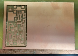
15. Once both the interior and exterior traces have been milled, press View on the Modelo. Shopvac or Dust Bunny the area. Remove the copper plate by pulling on the excess double sided tape. If you need to, use sand paper to smooth out the board in case the end mill you used was dull. 16. Congratulations! Buy yourself a F'real, you earned it!
Stuffing
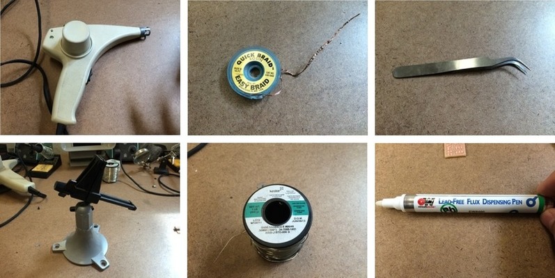
Finally, we have a circuit board! Now, we have to stuff it with components. To start, ensure you have all your tools available. Although the only thing you need is solder and a solder hand piece, I recommend obtaining a heat gun, copper quick braid, tweezers, a stand to hold your board, and flux.
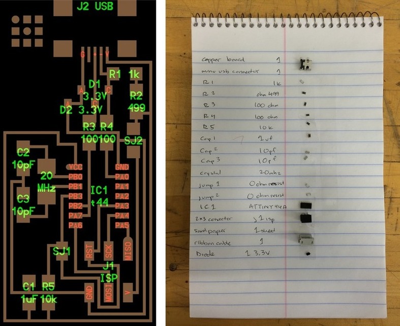
Also, given that all the components are smaller than my love for onions (and I really hate onions), it is a great idea to make a checklist of all the components you will solder on. Using the board diagram provided, I made a checklist of all the components I needed, added some double sided tape to the checklist, and as I obtained new components, I tapped them to the checklist.
To solder components onto the board, begin with the smallest and most complex piece. This is the piece that requires the most room to work, so it is a good idea to do it first. Use a stand to hold the board down; You WILL need both hands to solder. Work your way down the checklist until all components are soldered. Be sure to fix any mistakes right after you make them, as it is more difficult to fix errors after all components are on the board.
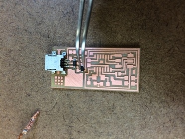
1. Start with applying flux to the area of the component you will solder. Flux helps the solder spread, which is particularly useful for components with many small leads close together, like the mini USB connector. Flux can come in either a pen or brush. Either way, apply liberally. Flux tends to rust copper, so be sure to remember to wash your board after you are done soldering all the components. 2. Apply solder. The best way to do this is to hold the hand piece tip on the area you want to apply solder to for 3 to 5 seconds to heat the copper. Then, bring the solder wire to in between the hand piece and the copper. You will have to experiment with the angles of both the hand piece and the solder wire, but once the wire melts, it should easily spread a into a thin film over the copper. 3. Using tweezers, place the component (be sure to check orientation, particularly of diodes and micro controllers) over the thin layer of solder. Use the tip of the tweezers to hold the component down, and gently touch the hand piece tip to the layer of solder. This should melt the solder enough to adhere to the component. 4. Now that you have two hands free (and the component is semi-attached to the board), use the handpiece and solder wire to add more solder to the ends of the component to create a smooth film from the component to the copper.
5. If you find that your component's leads are connected from too much solder, breath. You can use the copper braid to remove some. Lay the copper braid over the solder you want to remove. Place the end of the hand piece on TOP of the copper braid. Hold until the solder UNDER the copper braid melts. Quickly remove both the hand piece and braid. The melted solder will stick to the copper braid. Genius. I know. 6. If you find you placed a component crooked, or cannot fix the connected leads using the copper braid, you might want to just remove the component all together and start over. To do this, use a heat gun. Hold the top of the board vertically (so the components would fall if they were not soldered on). Use the heat gun to apply heat to the components you want to remove. Hold the gun for a few seconds until the solder holding the component melts and the component falls off. Word of caution: Use this only on isolated components, else you might loosen components that are nearby. 7. Repeat steps 1-6 for all your components.
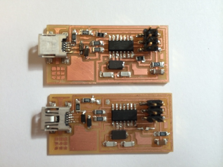
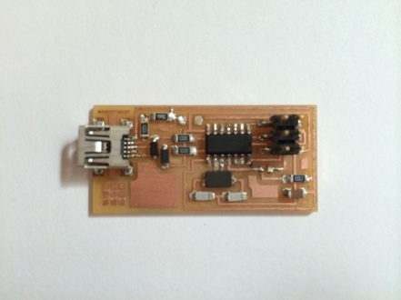
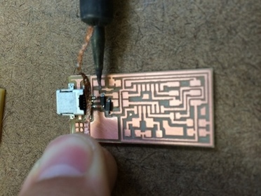
Soldering is an technique that takes a lot of practice, but is fairly easy to learn. To prove it to you, below is a picture of the two boards I made. The top board has many imperfections. The trace mills are thick, the components are crooked, and there is a lot of solder on the board. In contrast, the bottom board (the second board) is much cleaner. In particular, the solder on top of the mini USB and of the micro controller is thinner, and smoother. The resistors are all aligned with the copper paths on the board. The traces themselves are also more defined since I sanded the board down more. Basically, by making a second board, I was able to improve a lot.