Talking to a Board, with an Interpreter

Overview
The best way to understand what is going on during this week is to draw it. I want to start by thanking Matt Edwards for his help and patience when I put on a confused face after he said things like "AVR fabISP GCC FTDI," and countless other acronyms that I am still not all too familiar with. The following image shows exactly what is happening when I say I programmed my board. This image also helped me debug when, of course, my board did not work. The following tutorial is assuming you are using a Windows 7 64-bit machine.

Software Setup
Arduino
To get started with Arduino, first install the Arduino IDE from http://arduino.cc. Then, you will need to add ATtiny support to the Arduino IDE. The best way is to follow the directions from http://highlowtech.org/?p=1695, a great tutorial from the MIT Media Lab.
Also, in the meantime, let us add drivers for both our FabISP and for the AVRISP MkII. The FabISP driver (USBTinyISP) can be downloaded from http://mightyohm.com/blog/2010/09/fixed-usbtinyisp-drivers-for-64-bit-windows-7/. The AVRISP MkII USB driver for Arduino can be downloaded from http://www.visualmicro.com/post/2014/01/17/AvrIsp-MkII-Usb-Driver-for-Arduino.aspx.
Hardware Setup
The hardware setup is best explained with the schematic above. You will need a computer with two USB ports that has the drivers in the Software Setup section installed. You will then need an ISP (In-System Programmer). The point of the programmer is to interpret the compiled code in your computer and translate it into something your target board can understand. To connect the ISP to your target board, you will have a 2x3, six end connector. The off-the-shelf AVRISP MkII has one attached. However, if you are going to use your previously made FabISP, you will have to make this cable yourself.

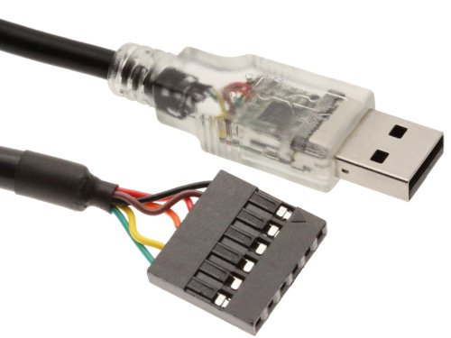
For power, you can either create an external power source (3-5V) to power your board, or you can use an FTDI cable, like the one seen above. The FTDI cable is used to move information from your target board to your computer, but for the time being, I will use if to power my board. A third way to power your board is to use your FabISP. I tried this, by removing only one 0 ohm resistor. However, I couldn't get it to work =/. Finally, you will need a target/circuit/LED board. Just a heads up; I will use these three names interchangeably for this tutorial. If you have all this, you are ready to program your board!
Programming Your Board
Arduino
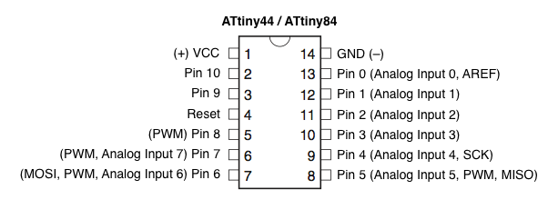
Arduino IDE has built-in examples that you should use. I used the "Blink" and the "Button" examples. Be sure to change the pin number on the example to the pin associated with your LED or button. Caution! Pin numberings on Arduino don't always match the physical order on the chip. The image below show the physical order (inside) and the Arduino pin number (Not in parenthesis, next to the pin drawing).
Once all hardware is connected and you have changed the pins on an example Arduino program, follow these steps to get programs onto your board.
1. First, select the appropriate board and timing source. If you followed the steps in Software Setup above, you should be able to pick "ATtiny44 (internal 1 MHz clock)" from board submenu under the Tools menu. Although you have likely put a 20 Mhz crystal on your board, start with 1 MHz to ensure it is working properly. 2. Then, select the appropriate programmer. If you are using an off-the-shelf AVR MkII, pick "AVRISP MkII" under the programmer submenu under the Tools menu. If you are using the FabISP you build earlier in the semester, pick "USBtinyISP." 3. Then, select "Burn bootloader" to set the fuses and get timing right. Even if you have a crystal, again, I suggest starting with an internal clock, just to be safe. 4. Finally, select "Upload using programmer" to upload your program.
Congratulations! You programmed a board! If it didn't work for some reason, read through the tips on the side.
SETUP 1: Arduino + AVRISP MkII + LED Mark I
The first setup I tried was using the Arduino IDE, an AVRISP MkII programmer, and my LED board (Mark I) from Electronics Design. And of course, it did not work the first time. I was sure the AVR MkII and FTDI cable were fine since they were purchased and used by others before me. My six lead connector was also fine, so it must have been my LED board that was acting up.
Fixing the LED board
After not finding out what was wrong with my board using a voltmeter, I tested my setup with Richard Li's board. I was able to successfully program his board to blink. Richard inspected my board and was able to find a flaw! I accidentally connected a trace from the power supply in my FTDI connector, through my two LEDs (and resistors), and ending at VCC of my 6 pin connector. Essentially, the pins never lit up because they were not connected to ground. Well then, I tried connected them to ground haha. I used an xacto knife to cut the trace and soldered a wire from my LED to the ground connector of my 6 pin connectors.

Did it work?! No. What do you think this is?
Redesigning the LED board
So I decided to simplify my board. I ended up using only one LED and one button, cleaned up some traces, and checked design rules in Eagle. I milled the board, and stuffed it with components.


It works!
 Link to Setup 1 videos.
SETUP 2: Arduino + FabISP board + LED Mark II
Fixing the FabISP board
I tried removing just one 0 ohm resistor, to power my LED board through the FabISP board, but it did not work. So I resoldered the second 0 ohm resistor, and reprogrammed my board following the tutorial by Anna France.
It works!
I was successfully able to program my LED to turn on and off depending on the state of my button using my own FabISP! #FeelsGood

 Link to Setup 2 video.