LED that changes color
Murphy's Law
Listen up! Seriously. I have, unbeknownst to me, been selected by the gods to be the epitome and personification of Murphy's law. Consider this a sacrifice. I have made all the mistakes you believe you have avoided. Voltage inputs, accidental programming, smoking board? Yup. All that is in here. So grab a BEvERage, kick up your feet, play some Miguel (its just soothing R&B music), and be ready to laugh at my ridicule. I am writing this week's post for you, in the hopes that you do not make these error.
You can thank me anyway you see fit.
Mistakes
Background
The idea for this week was to combine last weeks accelerometer board (which I was not successfully able to produce a pretty GUI for since the data was very noisy) with an RGB led that changed color depending on the direction of rotation of the accelerometer. Pretty straightforward.
Regulators require an umph!
Since I used Neil's board as a starting point for designing my RGB + Accelerometer board, without thinking, I added a 5V regulator to my board to give the LED 5V of power. The problem is that I used my FTDI cable, which already outputs 5Vs. So what happens when you add 5V to a 5V regulator. Nothing. Literally no current came out the other end. Perhaps I was sleep deprived so I didn't catch this, but we were definitely taught this in lecture.
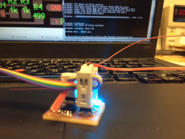
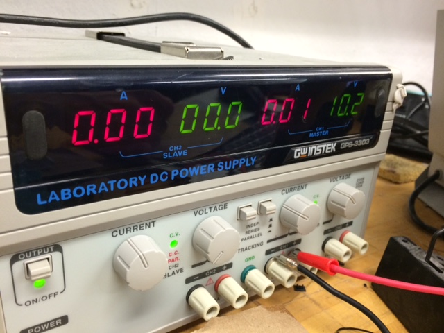
Solution ended up being connecting the board to a power supply. I juiced it with 10V, and Voila! The LED turned on. However, the color was not consistent with the accelerometer. To determine which of the two components was not working, I programmed the board with Neil's hello.RGB.45.c code, which just transitions the LED between the three colors. The LED lit up successfully, meaning my accelerometer was not working. I ended up making a 9V battery connector to keep testing the board without the need to use a non-portable power supply.
Connecting Gnd to VCC
My accelerometer from Input Devices week was very finicky. The TAs were not sure why the readings were switching back and forth between 0 and 128. After hours of debugging in both C and Arduino, we concluded that perhaps the accelerometer was just not functioning.
Starting from scratch so as to remove any ambiguity from my board that would cause the accelerometers to work, I used a simple 2axis accelerometer board to test the accelerometer independently. Milled the board, soldered on the pieces, and connected the board to my computer. This is when I got the dreaded rc=-1 error! This error that basically tells you "hey, something is wrong" but doesn't describe anything. I successfully programmed my blink board again using the same setup, so I confirmed that my computer, micro usb, fabISP board, 6 cable header, and FTDI cable all worked. It was the board that was wrong.
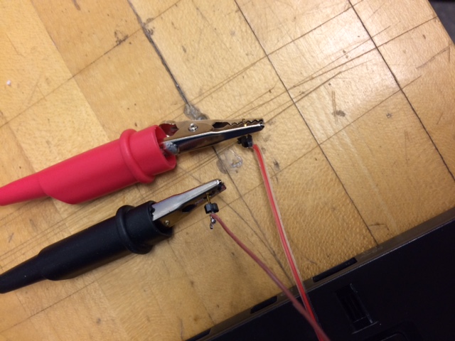
Taking a voltmeter, I noticed that the vcc and gnd pins of the 2x3 pin header connecting to my fabISP board did not have a reading. The power from the FTDI cable was not being transferred along the board. After testing various points on my board, I realized I must have connected the ground and output lines of my 3.3V regulator together, thus sending 5V to my accelerometer and frying it! Good thing I had one more! Back to the milling board.
Non Functioning Regulator
Filled the board again, stuffed the components, ensuring that my ground and output pins and lines from the regulator were not touching, soldered the rest of the board, and connected it to my computer. Again, I got the infamous rc=-1 error. UGH!
I took the voltmeter again, and as I was trying different leads, my finger touched the accelerometer and got burned. The accelerometer was very hot! To the point I couldn't it in my fingers. I disconnected the FTDI cable to remove power and let it cool. I switched the FTDI cable in case that was the problem (I was using the Amazon bought cheap version, so I always feel like it is an issue). Tested the new FTDI cable, and sure enough, 5V were coming out. Plugged my board back in, and the accelerometer got hot again. It started smelling funny, so I unplugged it. Great. I fried my board again.
To debug, I removed the accelerometer from the board using a heat gun, and plugged the FTDI cable back in. I tested the voltage at different points and found that the output of my regulator was 4.3 volts, not 3.3 volts. Apparently, if you give the accelerometer 5V (like in the first mistake), it just stops working. But if you give it 4.3 volts, it struggles to work, gets hot, smells funny, and then stops working. Turned out the mistake this time was not checking that my regulator did was it was supposed to do before powering my board. Lesson learned. Lets do all that again.
Accidental Attiny44 and 45 confusion
I ran over to the IDC shop to get some more accelerometers because I fried the two I had in our section. Thanks guys for being so accommodating!
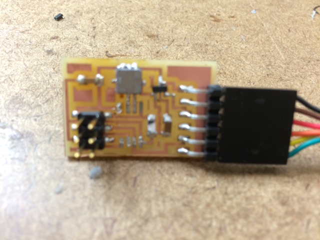
Milled the same board again and began stuffing it, but this time, rather than working from inside to out, bottom to top in the order of soldering like Neil recommends, I soldered the 6 pin FTDI header and the regulator first. And only that! Before soldering anything else, I plugged in the FTDI cable, and checked that the voltage on the output of the regulator was correct. And it was! Whew! With that check underway, I continued soldering the rest of the pieces, repeatedly checking the output of the regulator as I soldered a new component. The finished board looks great.
Finally, I plugged in the board again! Plugged it in, ran "program-usbtiny-fuses" and it looks like it ran great. Then did "program-usbtiny" and it ran smoothly! Finally, I had a board I could communicate to! Let's get to work right? Wrong!
I ran "program-usbtiny" again because I made changes to the c code, and I got the dreaded rc=-1 error! Weird, it was just working. I tried used "avrdude -c usbtiny -p attiny45" to ping everything, and now I am permanently in the rc=-1 error =(. Nothing I did fixed it.
Turns out I had used the wrong makefile for setting fuses, one that might have told it to use a crystal when I didn't have one on this board. I had added a program-usbtiny-fuses function into Neil's makefile since it didn't have one, but I took it from a makefile that was talking to an Attiny44, not a 45. I basically told my Attiny44 to talk to me through a crystal, which didn't exist on the board. My b!
There are three solutions to this. (1) Hook up a crystal to the pins it wants it on, (2) reprogram it using a high- voltage programmer, which we don't have, or (3) throw it away and replace it with a fresh one. I chose #3.
So did it finally work?! I don't know. Im going to bed. Ill update you next week.
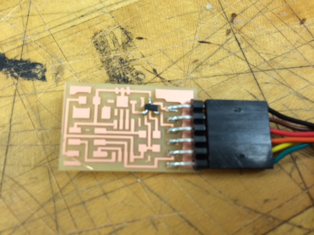
LED changing color
But just so I dont tease you, here is the RGB board that did work with the power supply in lab. Currently only cycles through two colors based on time, but I will change it to change color based on accelerometer position. The accelerometer board should be done soon.