Electronics Design
This was one of the more daunting and useful weeks for me because I have be wanting to work more with electronics for a while. I've gotten by using tutorials and some off the shelf circuits, but I hadn't gotten round to learning the basics of designing and building my own.
This week's task: use Eagle (or another circuit design software) to (re)design a microcontroller board (Neil's echo hello-world board. Then, using the techniques from week 2, mill and solder the PCB. Finally, programme said board using the programmer from week 2, and test it out with a simply python script.
Trying to Use Eagle
Eagle's interface is poorly designed, but it got the job done in the end.
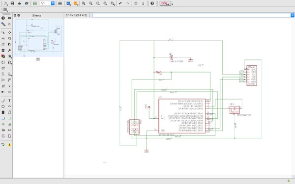
Designing a board in eagle is split into two windows and parts, the BOARD and the SCHEMATIC. The schematic is like a logical representation of the board, which is what your PCB looks like. Never allow these two windows to become unlinked, as you can never link them back again and all your work will be ruined.
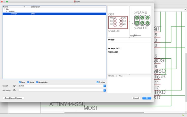
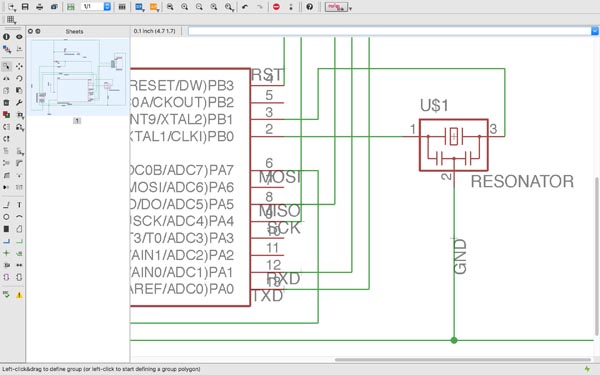
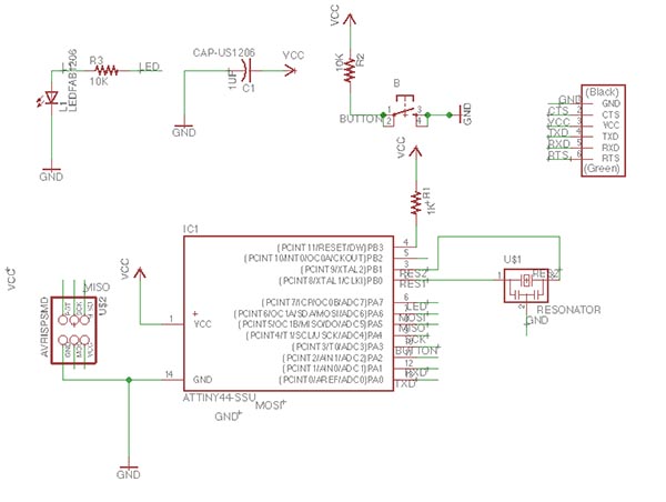
Some important things to remember: 1) selecting the parts is overwhelming if you don't know what you're looking for. Luckily in this case we were mostly using Neil's fab.lbr library. When you click add part, you're given a menu with Eagle's preloaded library of every conceivable electronic component with their proprietary product codes and each with a subselection of different sizes and variations. The search bar requires you to search for the (potentially abbreviated) name of your component in exact terms. I imagine it's a bit of a pain until you get used to the regular parts you use and buy. The numbers in the codes (e.g. RES0402) generally refer to the dimensions of the component, e.g. 0.4x0.2mm. 2) When moving parts around you need to click on the little cross at its center. Right-clicking with a selected part is a quick way to rotate it. If you choose to select a group of components, inexplicably the rotate command is [ctrl+right click > rotate group]. 3) Use the [view > grid] menu to set the baseline grid of your canvas, and the granularity which will determine the increments by which your components can move about (do people really work in milli-inches??). 4) NAMES are important and parametric, so if you have a bunch of spatially separated components whose connections lead to the same name, e.g. GND, they are connected. Use LABEL to label the parts by their names (annoyingly time-consuming but useful).
I found it difficult at first to get my head around the topological nature of thinking about circuits, i.e. laying the schematic out in terms of connections rather than spatial relationships (they come later). Initially for my own sake I drew connecting lines between all of the parts in the circuit as if I were arranging the board, but I soon realised that this is both unfeasible (so messy and criss-crossed it's visually useless) for more complex schematics, and it also creates a huge mess of connecting routes in the board view. So I proceeded to take my circuit apart again and lay the schematic out in separate clusters of components using the names function to connect them.
Laying out the Board
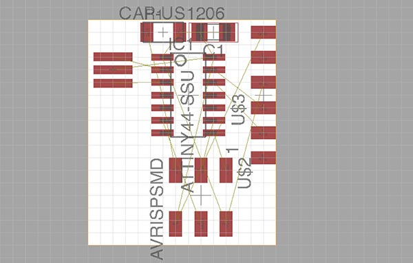
Onto the board. You start out with a dense and random cluster of components with an indistinguishable number of connecting lines between them, in a colour barely distinct from the white of the canvas. Eagle could make this easier for you but it generally doesn't. Laying the board out is a fun and mostly frustrating puzzle of making sure all the connecting bits connect in the right way in a relatively tight space, in such a way that none of the routes conflict with one another and that the space between the routes is not so tight that the PCB mill will ruin them for you.
It's a little bewildering at first but once the parts are out in logical way and I established where the GND and VCC lines were going to go, it became more a question of how to optimise the use of space on the board. I managed to get it to a pretty cosy fit without having to use any bridges (in the form of 0ohm resistors across routes).
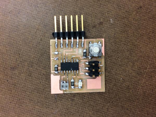
It was only after the first few attempts at milling the board that I realised that a few lines were not getting properly cut for being too close together. It took a couple of iterations but eventually it all came through. I used a route width of 12(milli-inches??) and a board with total dimensions of around 28x28mm.
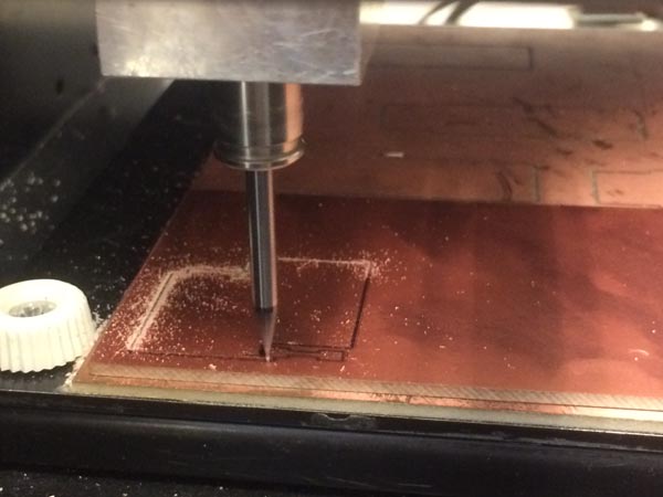
Milling
Cutting the PCB should have been the easy part but it actually took about 3 hours. I ran into several issues, but mainly that the default mods setting for cutting depth for the trace (1/64th endmill) of 0.004 inches was significantly too shallow for cutting the trace. This took at least seven or eight different attempts at adjusting the cutting depth (ending up with 0.010) which took far longer than expected because the MDX-20 mill, unlike the SRM-20, takes much longer to get over its buffer of instructions and reset its position.
Finally, with the cutting depth adjusted to a good level, I milled my board about 3 times, each time adjusting the space between routes to make sure the endmill got there. And a few for stupid mistakes like having the wrong black/white inversion for mods.
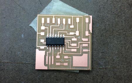
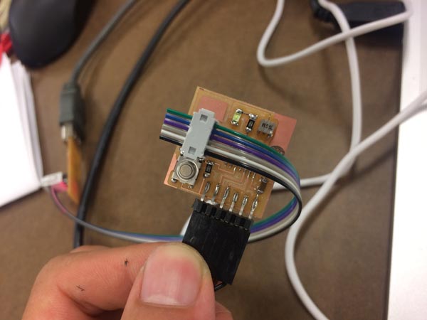
Soldering was relatively straightforward but also quite fiddly as this was a rather compact board. I was especially worried about the ATTiny44 since it has eight small legs, and I found it a bit tricky to solder them all quickly without the chip getting very hot and potentially fried. Had to remember the orientation of diodes (line marks the cathode, current travelling from anode > cathode > ground).
Programming the Board
This part felt pretty opaque at first. So we were using the in-system-programmer (ISP) from last time to programme a microcontroller (ATTiny44) board, so that it could handle the programmes we were going to upload to it later for inputs and outputs. Like building an Arduino, right? We were using the ISP to install its operating system, as such. That's how I was understanding it anyway.
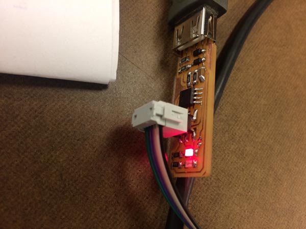
At first, I was following Brian's instructions using the firmware from week 2, which used the USBTiny interface. I immediately ran into problems though, namely that the board was failing to initialise, and potentially not being recognised by the ISP at all. avrdude was not reading my board. The only indication I had of anything working was that the red LED on the ISP would light up when I plugged the ATTiny in. As it turned out everyone else in my section was having quite a bit of trouble too; we tried instead following separate instructions to install the arduino firmware onto the board. Something seemed to be reading OK but when it came to actually uploading a simple sketch, I got the initialisation failure again.
Tragically I figured this meant that the chip was probably fried after all. Luckily I had a spare unsoldered PCB which hadn't failed previously, so I ended up resoldering the whole board (attempting to desolder the ATTiny's many tiny legs was incredibly tricky and I gave up when the heat melted off one of the thin copper traces). Thankfully, the second board worked perfectly. First I got the arduino blink sketch to run (outputting to pin 7 on the ATTiny board), and then I went on to programme Neil's hello-world echo board.
Hello Echo
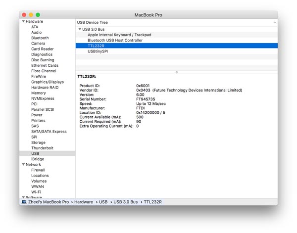
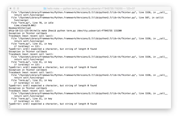
There were a few clues how to do this part hidden deep in the web 1.0 world of Neil's class site. Mostly there was this which I was able to follow until the final step of running the python program term.py with the command python term.py /dev/ttyUSB0 115200. After some googling, I found that /dev/ was a directory containing information about ports of the devices communicating with the computer, and that ls /dev/tty.* named the external devices plugged in, in my case returning /dev/tty.Bluetooth-Incoming-Port and /dev/tty.usbserial-FT94S73S, the latter referring to the serial number of the FTDI (Future Technologies Devices International Ltd?!) port that I was using for the echo board. Oh, I also had to install npm python serialports as a prerequisite to run the code.
Note: Serial communication is when data is communicated over a bus or channel one bit at a time, as opposed to in parallel. In Unix, /dev/ stores all the device files for the devices your computer uses. This includes everything from /dev/fd which is apparently the floppy drive file, as well as /dev/urandom, an interesting function which takes noise from other devices in your computer in order to generate a random number. Good to know for later maybe.
e.g. od -A n -t d -N 3 /dev/urandom generates 3 bytes of random number data.
Other potentially useful default serial ports: /dev/null is a bitbucket, or a black hole into which you can send things. /dev/zero is a quick way to generate a bunch of zeroes.
Apparently, /dev/tty is a "directory" that represents the current console. tty ("teletype") returns the user's terminal name. Running cap /dev/ttys000 opens a kind of echo console in which every input is immediately returned. So cp filename.txt /dev/ttys000 reads the file and returns it to the console, like using the cat command.
So with ls /dev/tty.* you search all the external teletype serial ports.