Output devices
So this week we were to program a board to work with an output device. I'm hoping to achieve the relatively simple task of driving some different motors, a DC (via an H-bridge), a servo and if possible, a stepper.
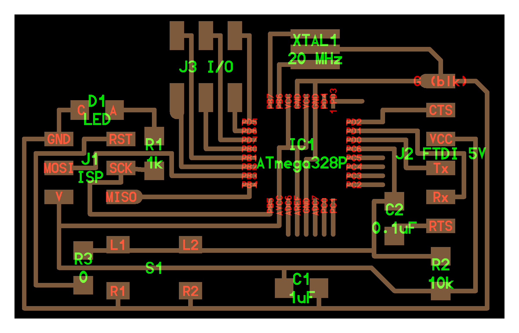
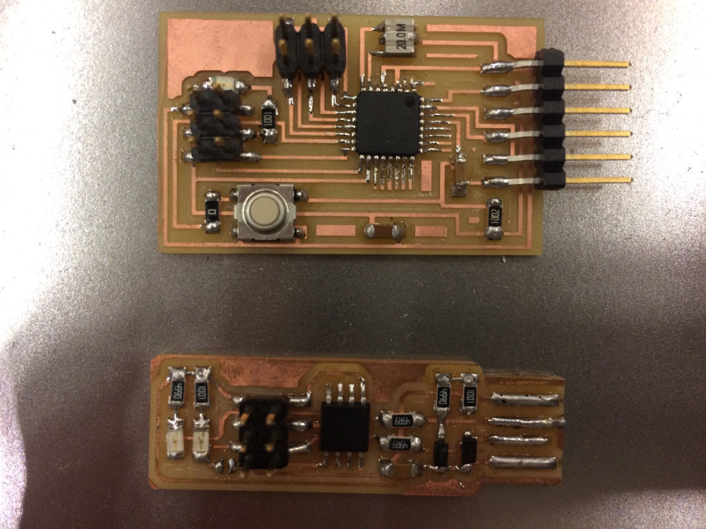
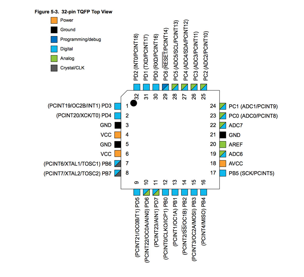
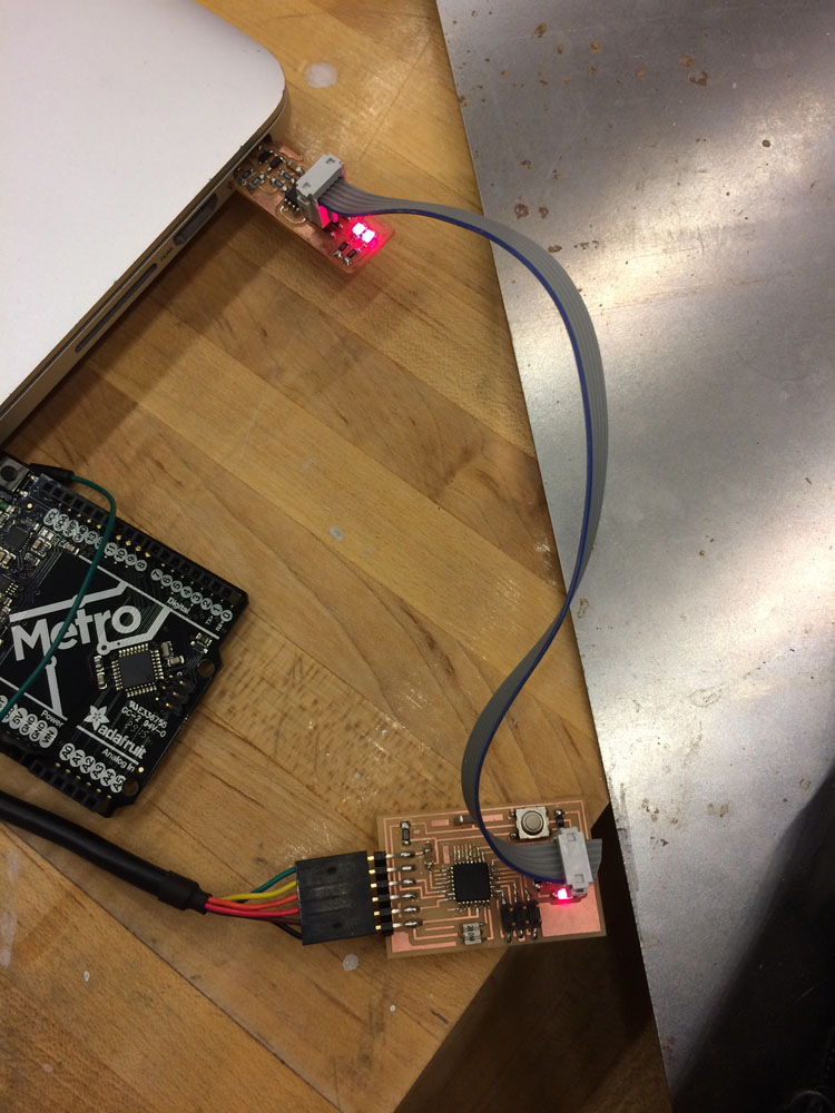
The first thing I wanted to do was to put together a new board which could support PWM for the servo, as well as having some additional digital I/Os for doing more stuff. To save time (I'll be getting more Eagle practice later) I ended up using Neil's hello.arduino board, which uses an ATmega328, with FTDI for serial and power and six digital pins for I/O activities. Milled the traces, stuffed the board (a tricky little chip), so far so good.
Bootloader Trouble
I was hoping that, as with the ATtiny44, it would be simple enough to burn the arduino bootloader onto this board (which uses the same chip as some arduinos) using the usbtinyisp. This turned out to be a complete nightmare, taking more than a couple of days. The problems were banal but multiple: primarily that I didn't have the right hex file for this particular board, which uses a 20Mhz resonator. The other major issue was getting the correct attributes for the ATmega328P, and getting the Arduino IDE to acknowledge it.
First the settings for the board had to be added to boards.txt, though where it should be located depends on the version of Arduino IDE you're using. As it turned out, I was using IDE 1.6.3 which meant that the custom board directory had been relocated to /Users/Zhexi/Documents/Arduino/hardware/ATmega328/variants/board.txt. In addition to this, following these instructions from Oliver Bucklin (863.14), I had to make a new hex file for the ATmega328P in the Arduino bootloader directory, Arduino.app/Contents/Java/hardware/arduino/avr/bootloaders/, by editing the Makefile to add a version of the chip with a 20MHz clock. Run the Makefile to generate ATmegaBOOT_168_atmega328_pro_20MHz.hex.
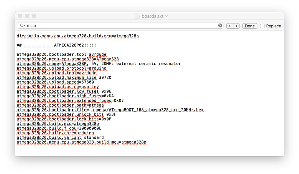
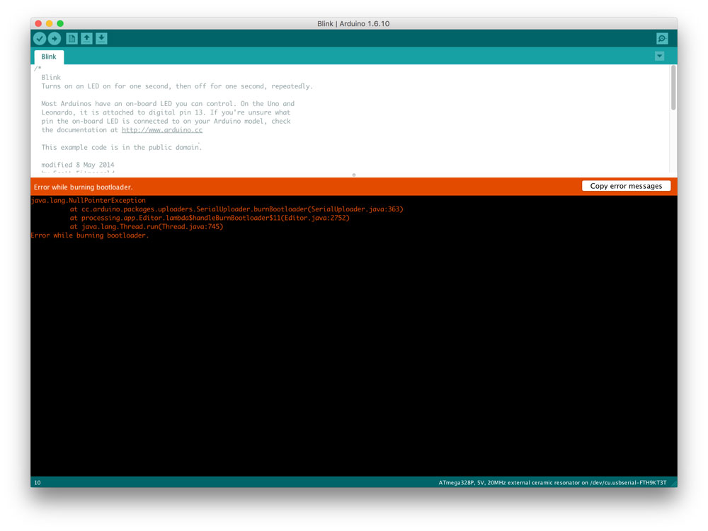
Still this was not enough. I went through a series of problems, variously relating to the identification of an incorrect signature in the chip (changing 0x14 under the ATmega328P section in Java/hardware/tools/avr/etc/avrdude.conf to 0x0F), and by fiddling around with the settings in boards.txt, platform.txt and the bootloader Makefile to make sure that all of the names are consistent (e.g. I found that, having adapted a version of Neil's code, I needed to change atmega328p20.upload.using=usbtinyisp to atmega328p20.upload.using=usbtiny). Different inclinations belonging to different IDE versions probably account for these issues. One inexplicable issue I kept returning to was a series of java.lang.NullPointerException errors with very few clues about their origin. In the end, after hours of searching through forums, I stumbled my way to a solution by installing a slightly earlier version of the IDE (1.6.0). In this version, the boards files were not installed in the sketchbook/libraries folder but in Applications/Arduino.app/.../boards.txt. After making the appropriate additions to these files (ATmegaBOOT_168_atmega328_pro_20MHz.hex, boards.txt, ATmegaBOOT_168.c and Makefile), the chip finally appeared in the IDE and I was able to burn the bootloader..!
Circuits and motors
My newly arduino'd board had a minor inconvenience. Unlike a regular arduino, it didn't have an auto-reset function, meaning that one the bootloader was burned on, only a single sketch could be uploaded and compiled. To get another sketch onto the board, you have to press the reset button on the fabduino either randomly or strategically. UPDATE: as it turned out this problem could be circumvented by using the ISP header to programme the arduino code (or C code) onto the board, rather than the messier process of going through the serial I/O. Either through File > Upload with programmer or by holding shift when you click compile.
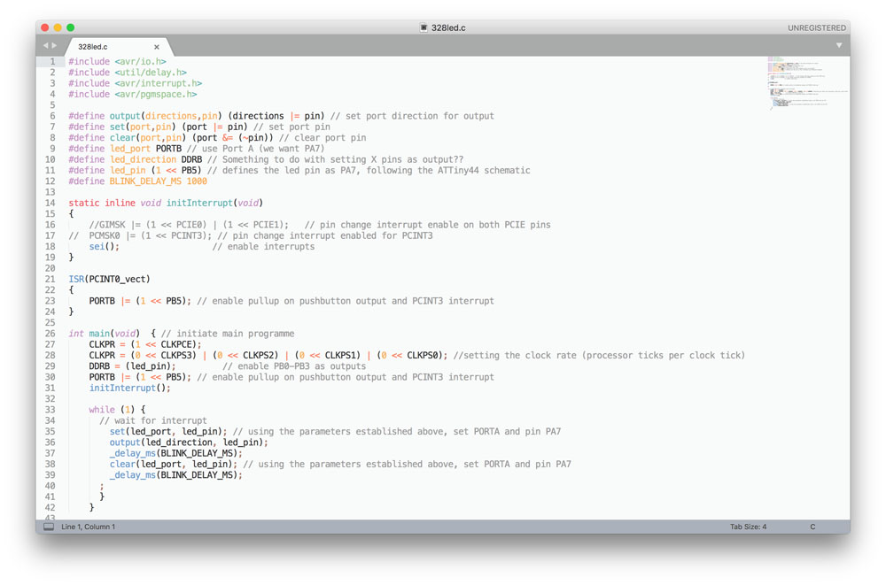
I also decided to try flashing to the board using a C program instead. I adapted the short program and the make file from week 6, using the pin-out on the ATmega328P, to get it blinking. This was pretty straightforward, but it taught/reinforced the way in which c programmes are installed. To work with thew new chip, I had to edit the makefile with its attributes; it took me a while but now I understand that the makefile is basically a catalogue of parameters and instructions, such as
program-usbtiny: $(PROJECT).hex
  avrdude -p t44 -P usb -c usbtiny -U flash:w:$(PROJECT).c.hex
,
make program-usbtiny in terminal. Then, consulting the data sheet to find the corresponding pins for the LED on my new schematic, I got it blinking.Onto the motors. Tentatively buoyed by LED-based optimism (this bootloading and debugging took the best part of a day and a half...), this is where more trouble began.
The goal I had in mind for the motor in my final project was a mechanism for raising and lowering the meat into the water/oil-bath. This would require some precision and would be best done with a stepper motor. However, I had not yet managed to get hold of a stepper but I did have a DC and a servo, so I set about controlling them with my chip.
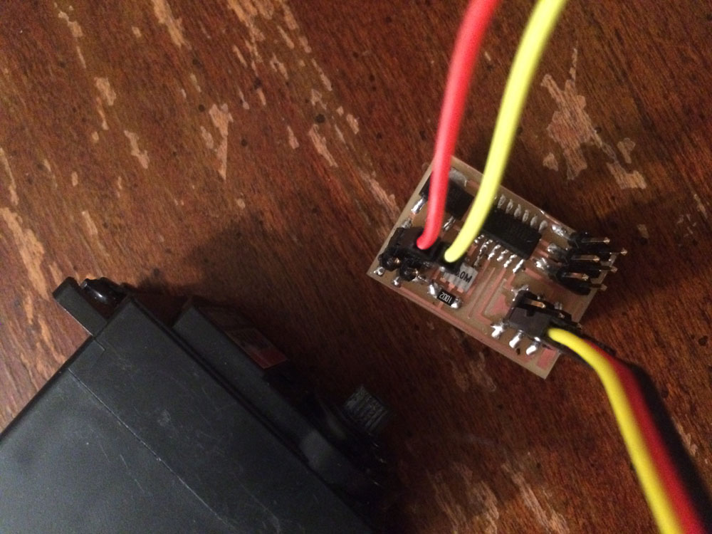
Straight away it seems, I ran into hardware problems, but debugging this took a long, long time. At first I didn't realise that in order to programme the H-bridge board or the hello.servo.44 board, with its ATTiny44 chip, you needed to power the circuit itself separately from the power which was provided by the ISP. For some reason, perhaps because we'd been using the FTDI for power until now, which these circuits did not require, it hadn't occurred to me that these boards would require separate power. This became pretty fiddly as the shop had run out of the appropriate headers, and the crocodile clips on the power supply had a very precarious hold on the servo board I was using. Perhaps because of this reason the board shorted, or because I was inputting the incorrect voltage, despite the relatively clean and smooth efforts of my soldering I just couldn't get the chip to run.
However, the whole reason that I fabricated the ATmega328P board was because it had a convenient number of I/O pins, including a two or three PWMs, with which I could drive the servo. I loaded up a basic servo control sketch, and had the motor twitching away, albeit again rather precariously because there weren't quite the right pins in the right places and we didn't have any jumpers around. Next week I'm hoping to redesign a board which will make the whole process more convenient, and to implement as part of a belt-driven pulley system using a stepper motor.