Embedded Programming
This week we learned to do some programming with the chips we designed in week 4, using a variety of coding languages. The first thing I tried to do was to write the most basic possible few lines of C, and get comfortable with the steps required to talk to the board. To be honest, at this point I'm still a little confused by what precisely the ISP is doing to the board, and how programs get loaded onto it. If this was essentially similar to an arduino, then the FabISP was programmer which programmed te "sketches" onto the ATTiny44 board. What then was the function of the FTDI cable? Could it be used for installing programs, as with the mini-USB input on the Arduino? Or was it limited by the fact that it was only for serial communication?
The first thing I did was to try and write, or partly adapt, a really simple bit of C code. This first one just sets the necessary ports and switches the LED on.
#include <avr/io.h>
#include <util/delay.h>
#include <avr/interrupt.h>
#include <avr/pgmspace.h>

#define output(directions,pin) (directions |= pin) // set port direction for output
#define set(port,pin) (port |= pin) // set port pin
#define led_port PORTA // use Port A (we want PA7)
#define led_direction DDRA // Something to do with setting X pins as output??
#define led_pin (1 << PA7) // defines the led pin as PA7, following the ATTiny44 schematic

int main(void)  { // initiate main programme

  //
  // main
  //
  // set clock divider to /1
  //
  CLKPR = (1 << CLKPCE);
  CLKPR = (0 << CLKPS3) | (0 << CLKPS2) | (0 << CLKPS1) | (0 << CLKPS0); //setting the clock rate (processor ticks per clock tick)

  set(led_port, led_pin); // using the parameters established above, set PORTA and pin PA7
  output(led_direction, led_pin);

  while (1) { // starts an infinite loop within this code block
      //
      // wait for interrupt
      //
      ;
      }
  }
And then a few tweaks to make the LED blink. Just beginning to become familiar with the most basic C operators (
~ is bitwise NOT; |= is bitwise OR); added the line #define BLINK_DELAY_MS 1000 and #define clear(port,pin) (port &= (~pin)) so it's possible to clear the pin as well as set it. The AVR has the native function of _delay_ms for setting millisecond delays. Then it was just a case of structuring it like the classic arduino sketch. I had to move all of the steps of the programme into the while loop - not sure if this is a good thing to do..#include <avr/io.h> #include <util/delay.h> #include <avr/interrupt.h> #include <avr/pgmspace.h> #define output(directions,pin) (directions |= pin) // set port direction for output #define set(port,pin) (port |= pin) // set port pin #define clear(port,pin) (port &= (~pin)) // clear port pin #define led_port PORTA // use Port A (we want PA7) #define led_direction DDRA // Something to do with setting X pins as output?? #define led_pin (1 << PA7) // defines the led pin as PA7, following the ATTiny44 schematic #define eggs 1000 int main(void) { // initiate main programme // // main // // set clock divider to /1 // CLKPR = (1 << CLKPCE); CLKPR = (0 << CLKPS3) | (0 << CLKPS2) | (0 << CLKPS1) | (0 << CLKPS0); //setting the clock rate (processor ticks per clock tick) while (1) { // starts an infinite loop within this code block set(led_port, led_pin); // using the parameters established above, set PORTA and pin PA7 output(led_direction, led_pin); _delay_ms(BLINK_DELAY_MS); clear(led_port, led_pin); // using the parameters established above, set PORTA and pin PA7 _delay_ms(BLINK_DELAY_MS); // // wait for interrupt // ; } }
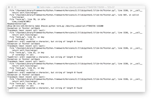
There were a few clues hidden deep in the web 1.0 world of Neil's class site. Mostly there was this which I was able to follow until the final step of running the python program term.py with the command
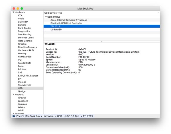
python term.py /dev/ttyUSB0 115200. After some googling, I found that /dev/ was a directory containing information about ports of the devices communicating with the computer, and that ls /dev/tty.* named the external devices plugged in, in my case returning /dev/tty.Bluetooth-Incoming-Port and /dev/tty.usbserial-FT94S73S, the latter referring to the serial number of the FTDI (Future Technologies Devices International Ltd?!) port that I was using for the echo board. Oh, I also had to install npm python serialports as a prerequisite to run the code.
Note: Serial communication is when data is communicated over a bus or channel one bit at a time, as opposed to in parallel. In Unix, /dev/ stores all the device files for the devices your computer uses. This includes everything from /dev/fd which is apparently the floppy drive file, as well as /dev/urandom, an interesting function which takes noise from other devices in your computer in order to generate a random number. Good to know for later maybe.
e.g. od -A n -t d -N 3 /dev/urandom generates 3 bytes of random number data.
Other potentially useful default serial ports: /dev/null is a bitbucket, or a black hole into which you can send things. /dev/zero is a quick way to generate a bunch of zeroes.
Apparently, /dev/tty is a "directory" that represents the current console. tty ("teletype") returns the user's terminal name. Running cap /dev/ttys000 opens a kind of echo console in which every input is immediately returned. So cp filename.txt /dev/ttys000 reads the file and returns it to the console, like using the cat command.
So with ls /dev/tty.* you search all the external teletype serial ports.