Electronics Design
Week 4
This week I learned how to use Autodesk's Eagle software to design a circuit board. The assignment was to copy the "Hello World" board from the website, design it in Eagle, cut the board, solder it and then program it.
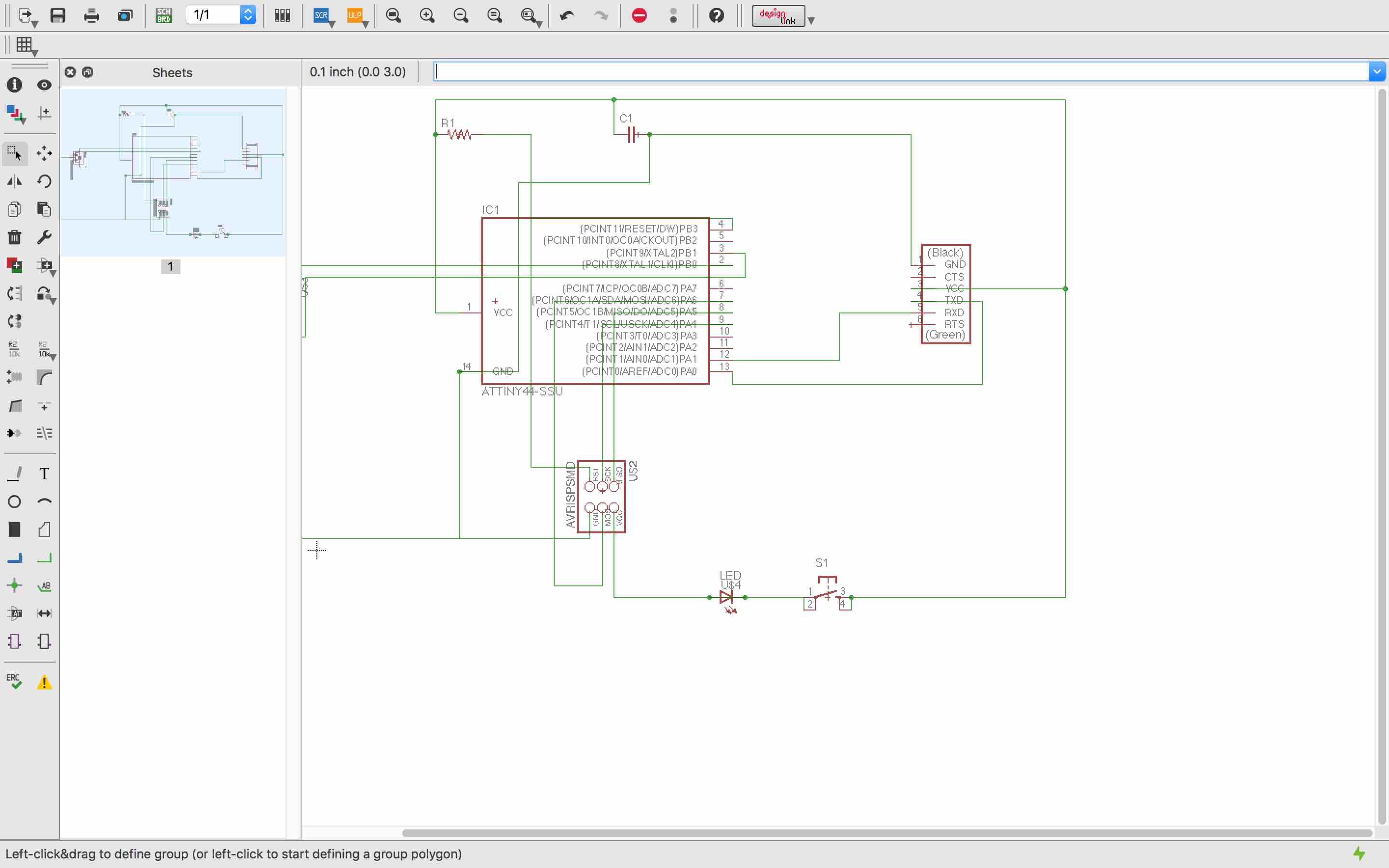
After spending some time in Eagle I got the hang of using the schematic. I downloaded the FAB parts library and inserted the parts necessary for the board in the schematic, and then used the "net" functionality to make connections in the schematic. Over time I learned that the cleaner the schematic, the easier it is to get the board right. For a couple of tries I had a messier schematic than the one above and it is easy to connect components to the wrong pins.
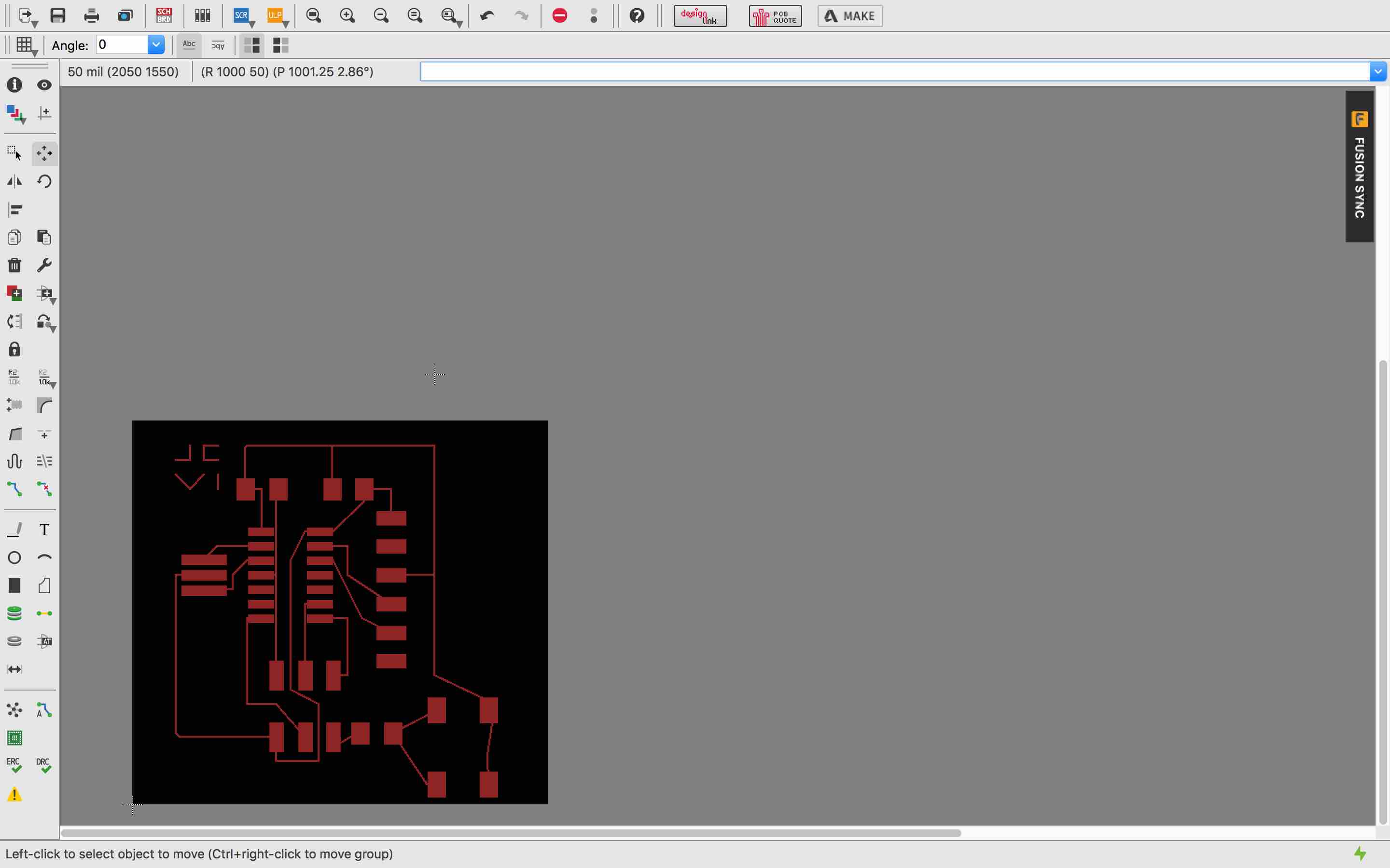
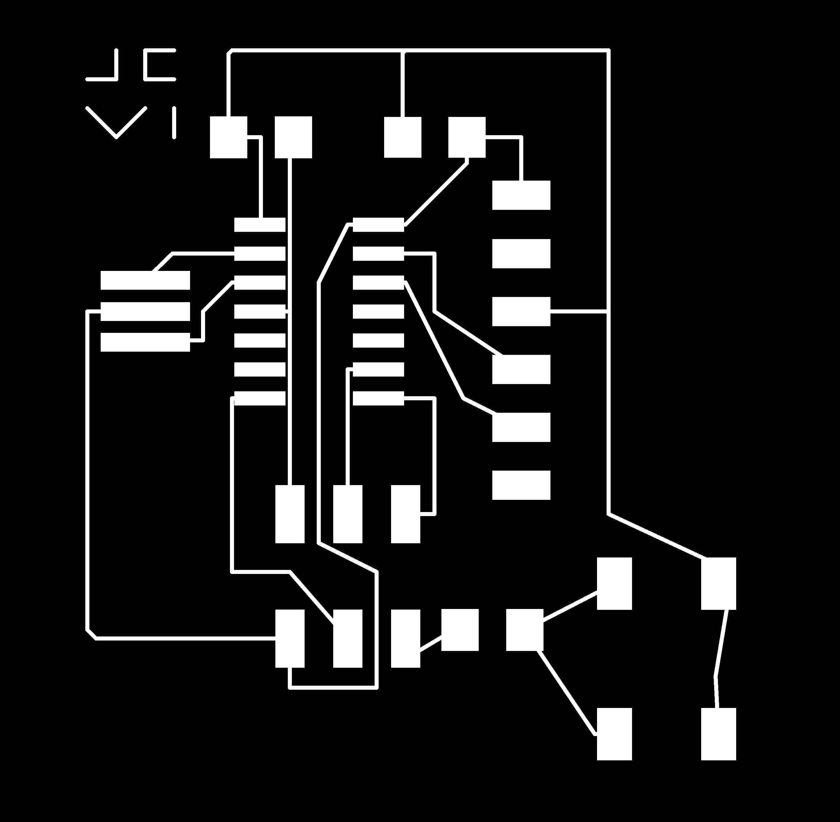
From here I used the "board" command to create a board design from the schematic. After moving and rotating the parts, I attempted to copy the routing from the design online. I then shrank the boarder size, saved the top layer traces as a monochrome png with dpi 1000, and exported the JPG. I created a boarder for the traces in Eagle using the rectangle tool in the bottom layer and then exported that as well.
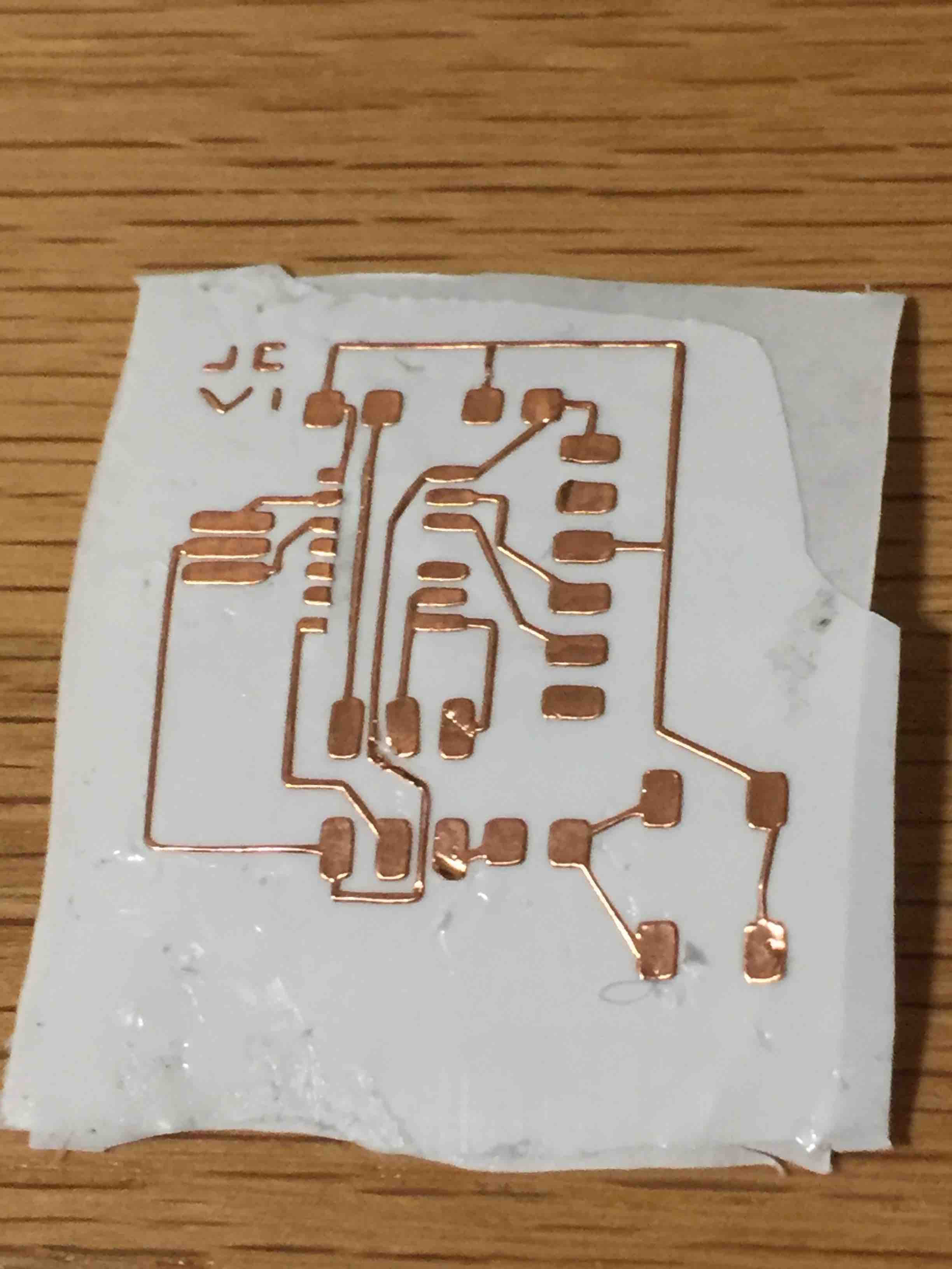
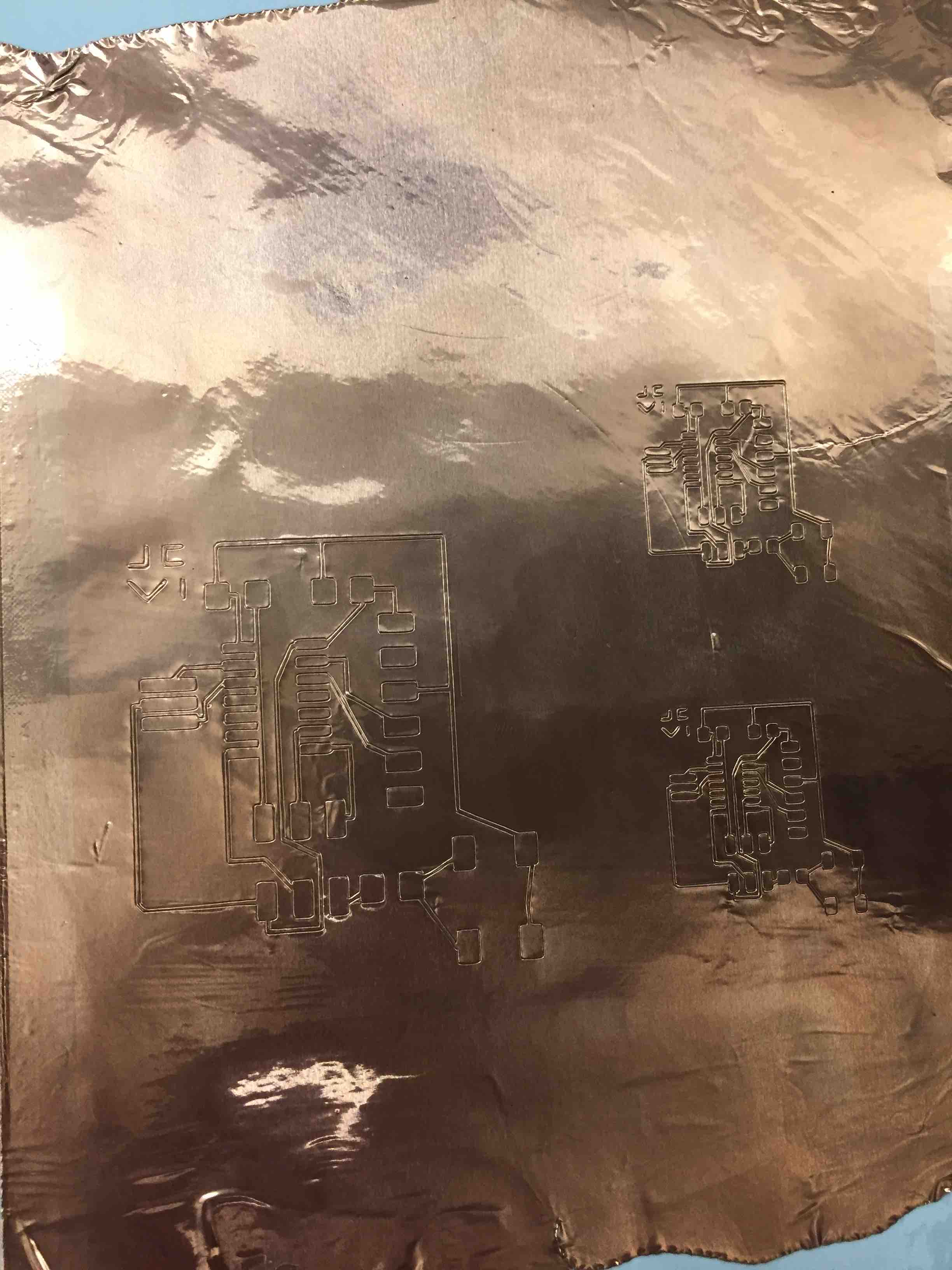
Instead of milling the board on the Modela, I decided to use the vinyl cutter to cut a flexible board. Because of this I didn't need to use the board outline png. I uploaded the traces png to mods and cut however because I was using a Mac for my designs, the vinyl cutter cut dimensions twice the desired size. This is due to the retina screen on the mac. I changed the dpi to 2000 to fix this issue. In the picture below you can see the first circuit I cut at 1000 dpi next to two others at 2000 dpi after I corrected my mistake.
After that I used an exacto knife to cut the unwanted parts of the circuit. With the help of my TF Dixon we identified a few issues with the circuit design and looked at ways to fix them. First, if one looks at my traces, a trace going through the middle of the ATtiny44 comes so close to the pads of the microcontroller on the design that in the real cut there was no distinction. We cut off a section of the pads using an exacto knife and a straight edge to fix this problem. I also remembered that I should've made the traces larger. When I make my next vinyl cut circuit board I'll use a command in Eagle that widens the traces. Finally, I forgot to put a 100 ohm resistor next to the LED to lower the current passing through it. Below is an image of the circuit I have so far.
Here I ran out of time, but I hope to finish the board with solutions to the problems I mentioned above later this week.