Output Devices
Week 8
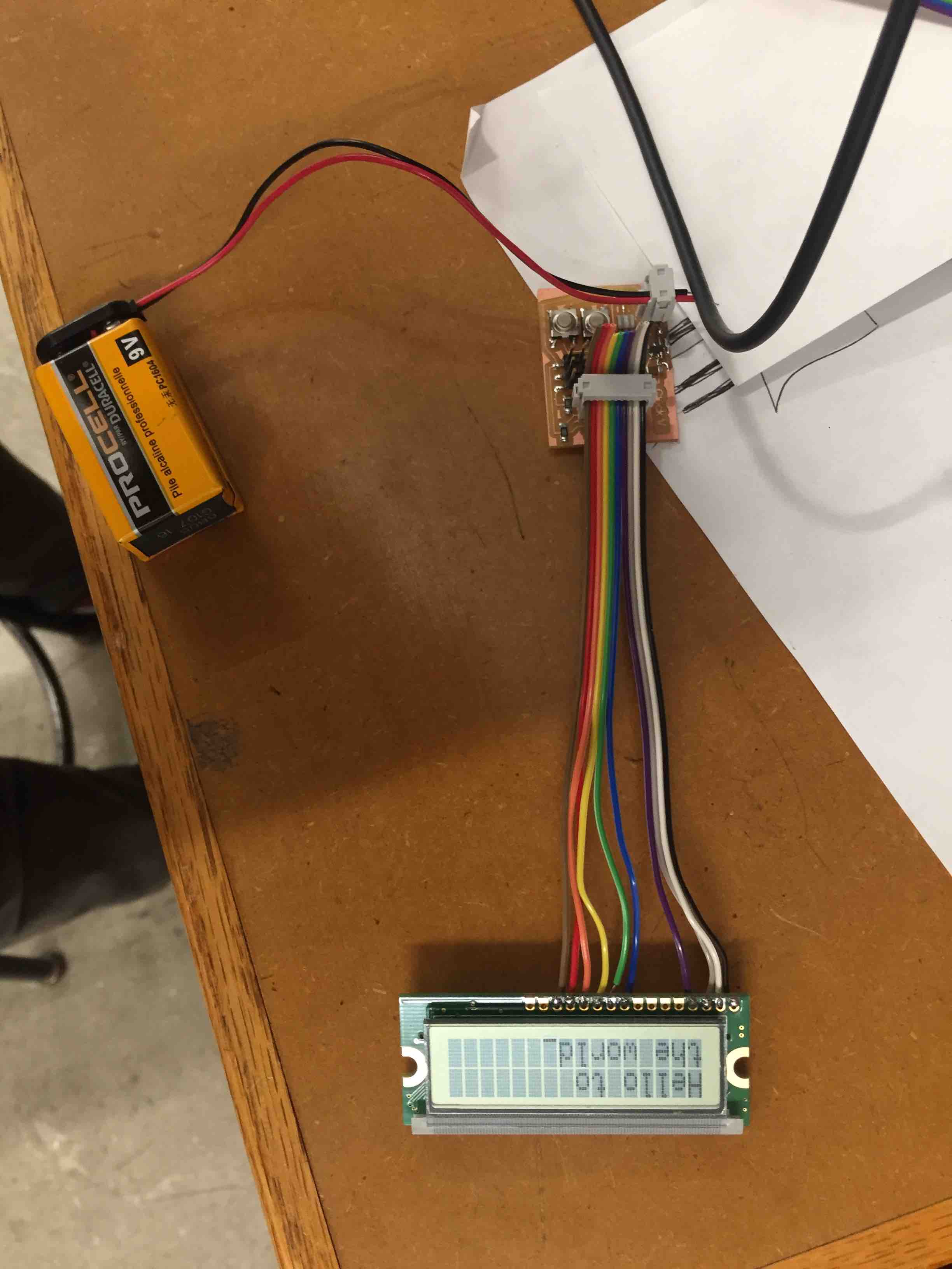
This week I wanted to make an LCD board that could eventually serve as a clock for the chess board in my final project. I modified the LCD board on the fab site to add two buttons which I would eventually click to change what the LCD displays. The goal would be to make the LCD count down when a button is pressed and stop when pressed again. If I could display two clocks on the LCD, one of them would stop and go when one button is pressed and the other with the other button.
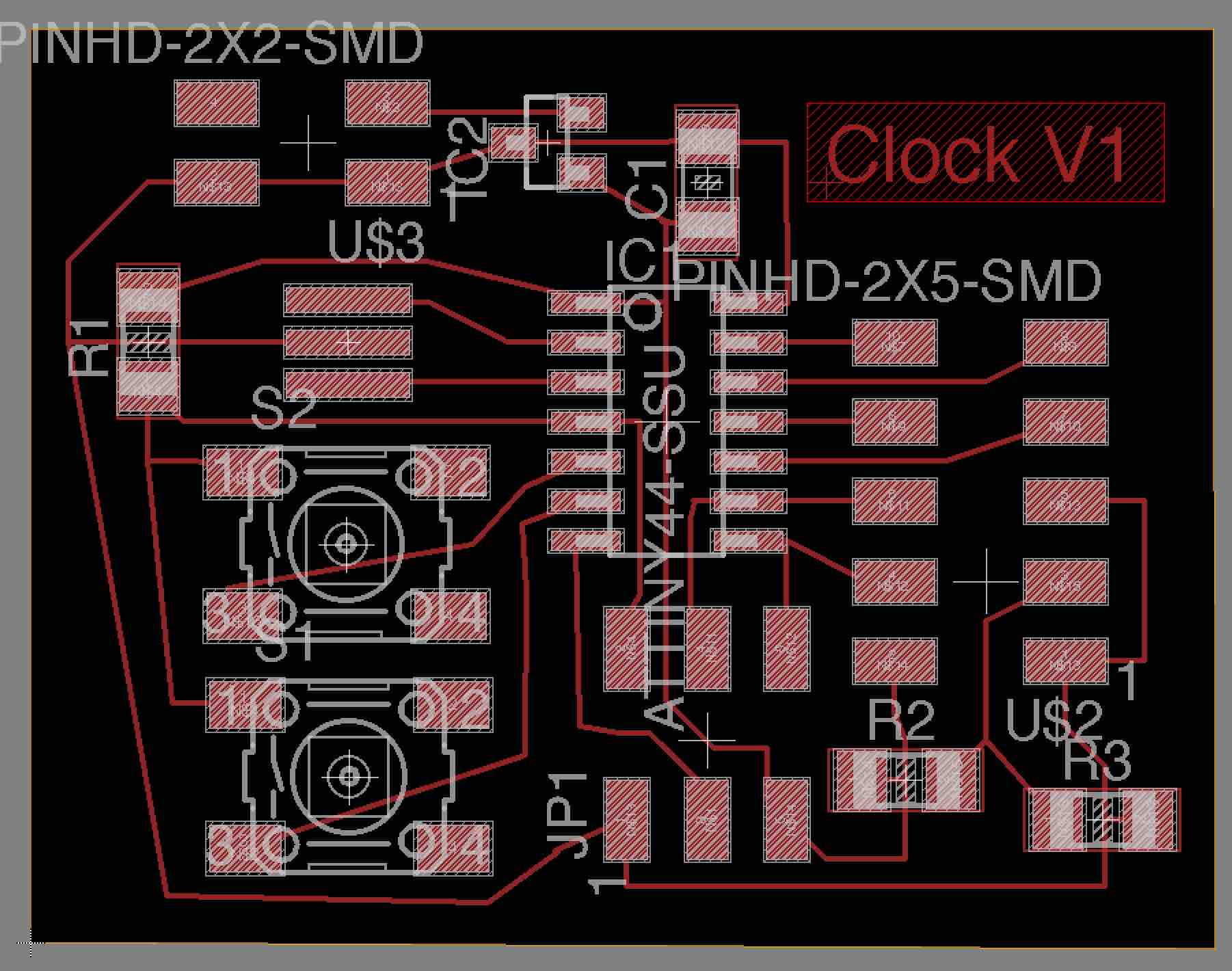
I milled the board with few problems and soldered it together although the pads for the regulator were different than those needed for the regulators we have in the Harvard section. I cut the proper size with an knife but cut too much so I had to solder a couple small solid core wires to complete connections in two places. I tried to connect pads without the wires but the cohesive properties of the solder are too great to cover long distances.
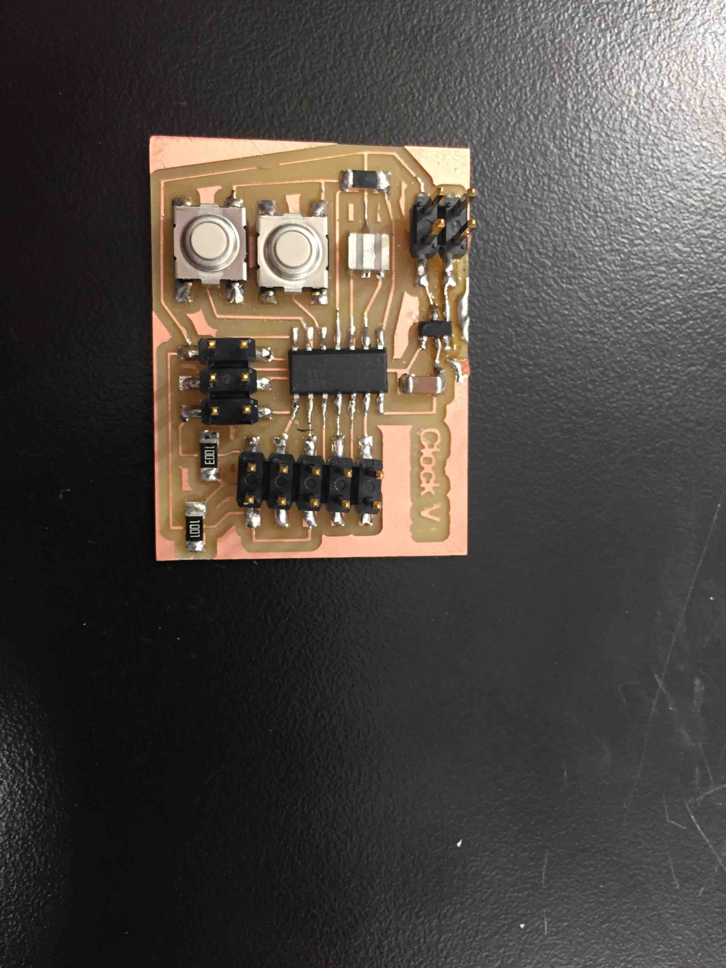
I tested connections with a multimeter and everything checked out. I then programmed the board using Neil's C code in Arduino. I soldered an LCD to a cable and plugged my board in and it worked.
In the coming weeks I hope to research how to put numbers in as characters and have the clock count down from a time, and stop based on the press of one of the buttons to form a stopwatch. This could eventually be used as part of the chess board clock I would build into my final project.