Final Project Updates
Week 14
My final project is a smart chess board that can sense the position of the pieces. As a very average chess player, I'm always trying to improve my game. The biggest part of this is running my games through computer analysis and then learning from my mistakes. When you play a game in real life, not on the computer, unless you write down every move it is difficult to analyze your games. I would like to make a chess board that can sense where each piece is on the board. I would like it to eventually record moves and export them to a computer for easy analysis. Another possible addition would be having the board keep time for both players.
For the board to recognize the type of pieces and locations of the pieces I am using sensors that pick up the capacitive load of each square of the board. I made and tested a generic input board for one sensor. I then designed a new board that would have one microcontroller sense two electrodes. I did this to get a hang of the code for multiple inputs. I needed to read a lot of the attiny44 datasheet and learn about ADMUX and assigning different bits to ADMUX to target different pins.

To get one microcontroller to sense more than two inputs I needed to read and learn about charlieplexing. I was inspired by Matt Keeter's multitouch board and wanted to design one of my own. After much reading, I decided to give it a shot. I had to learn many new tricks to do so. First was building a clean schematic in Eagle. By assigning labels to different connections I could make a clean schematic instead of a "spaghetti bowl" schematic. This organization proved critical so I could separate the subsystems of the board.
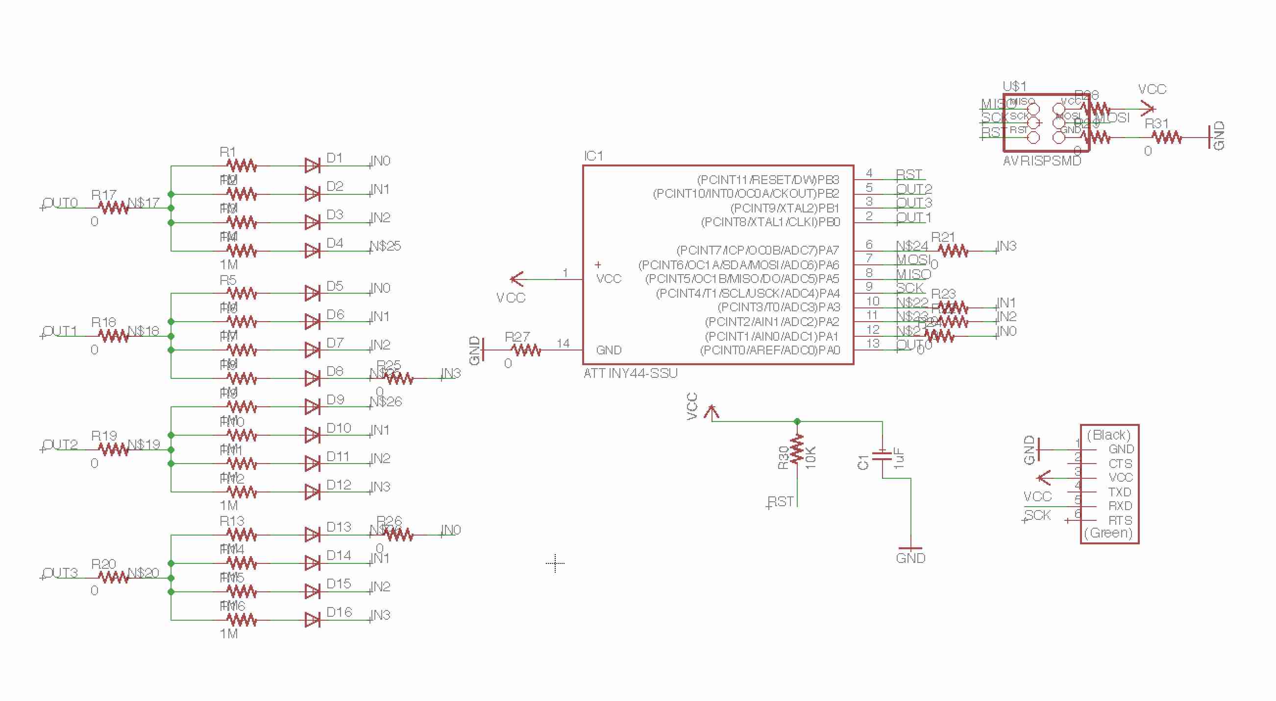
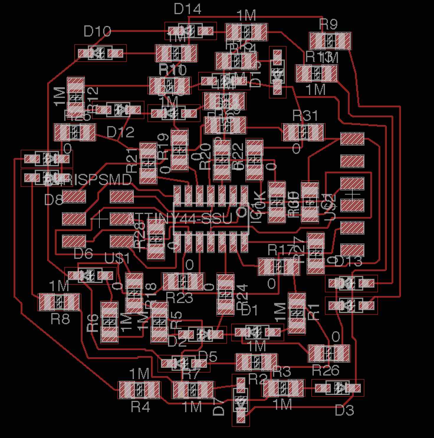
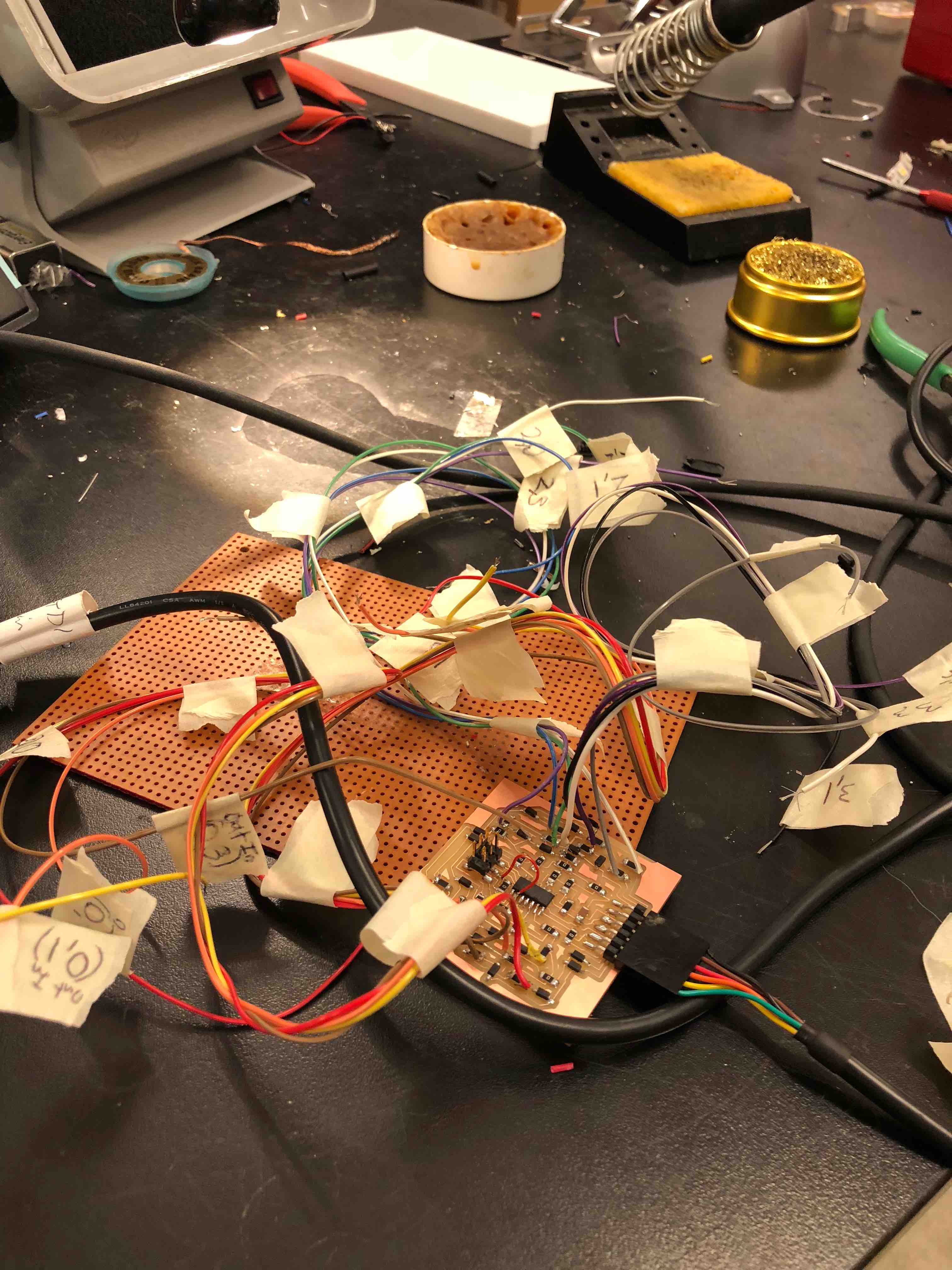
Routing the traces was extremely difficult and tedious. I needed multiple 0 Ohm resistors to jump traces and get the whole thing to work. To minimize shorts, I made the grid on Eagle extremely small. Still I had two shorts, one of which I was able to fix with an exacto-knife. The other I tried to fix with a knife but I screwed up and needed to connect the traces via wire. When it was done I used a multimeter to test whether the traces connected in the right way.
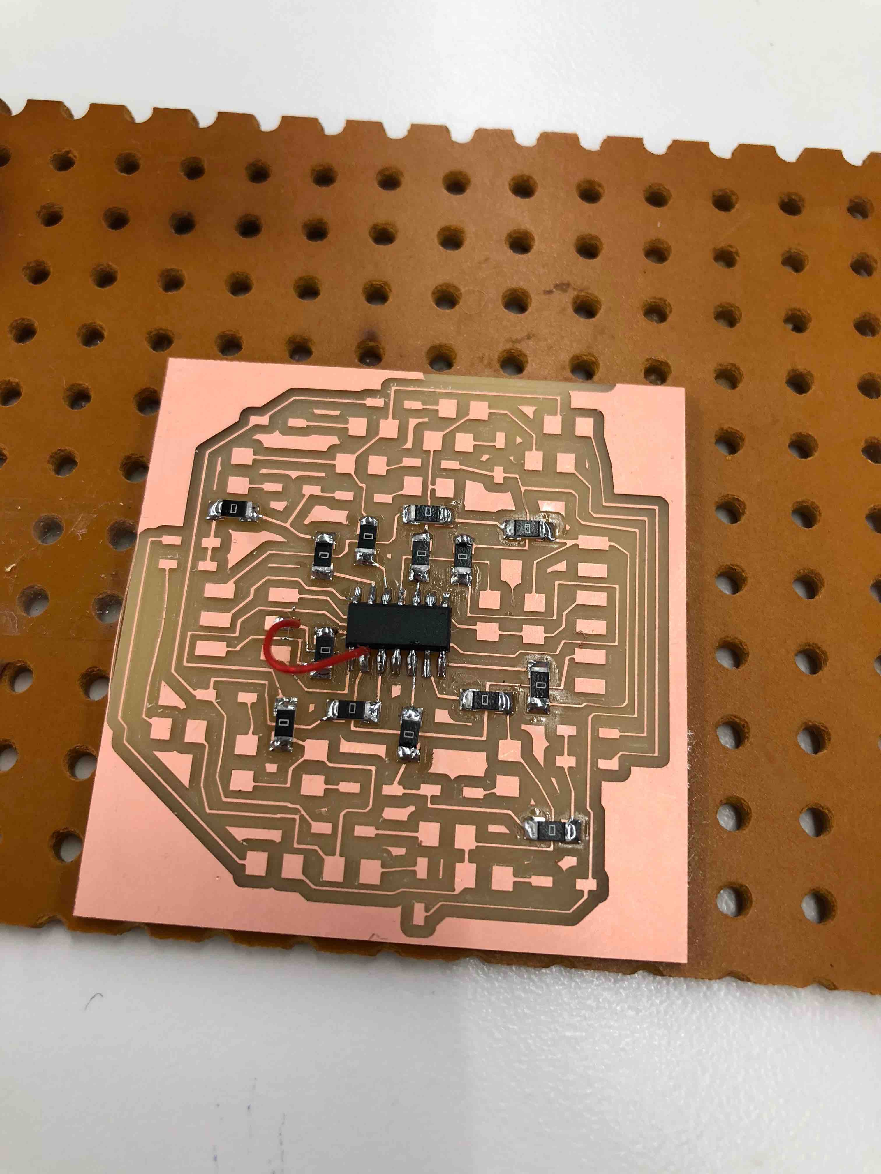
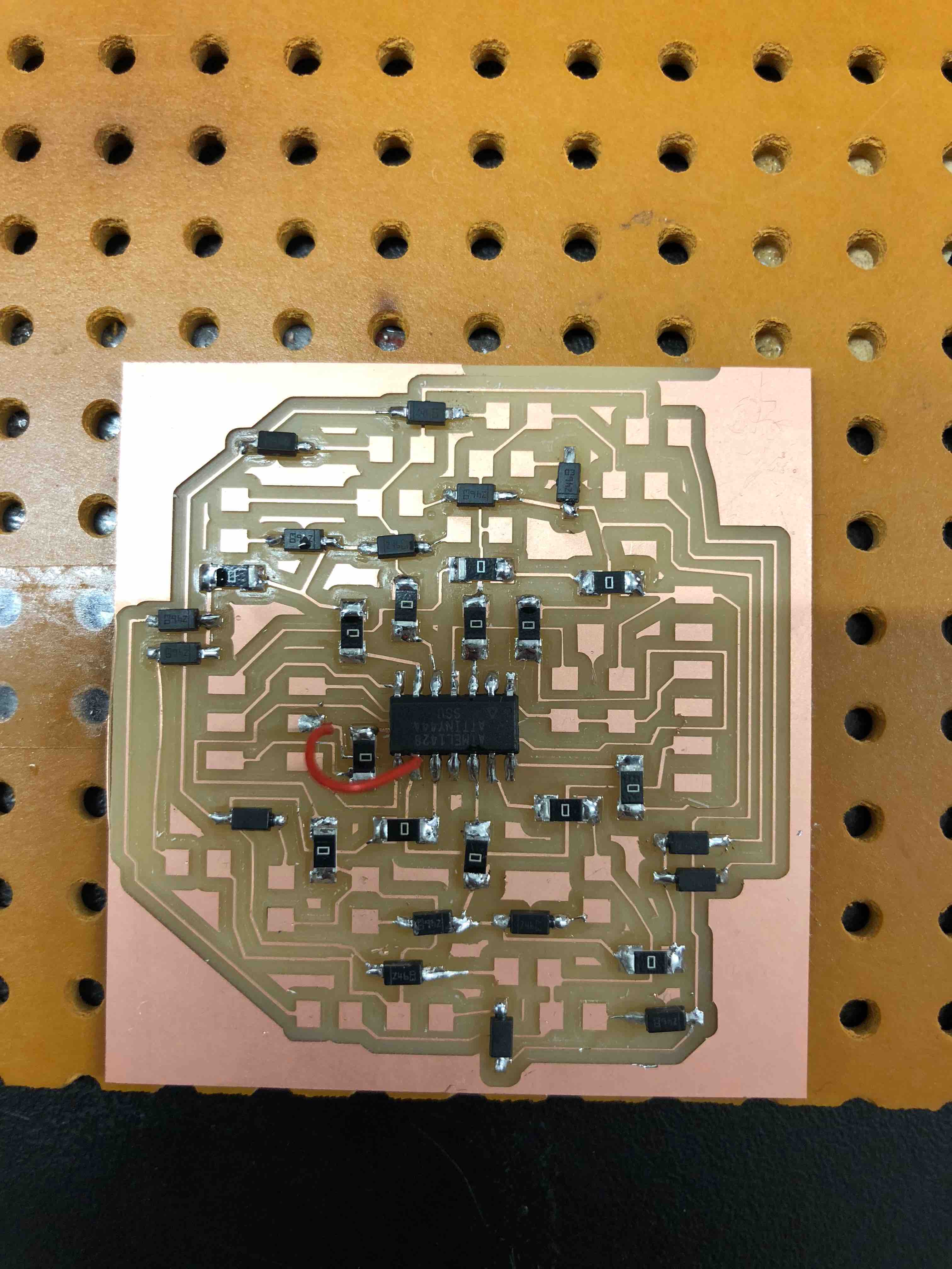
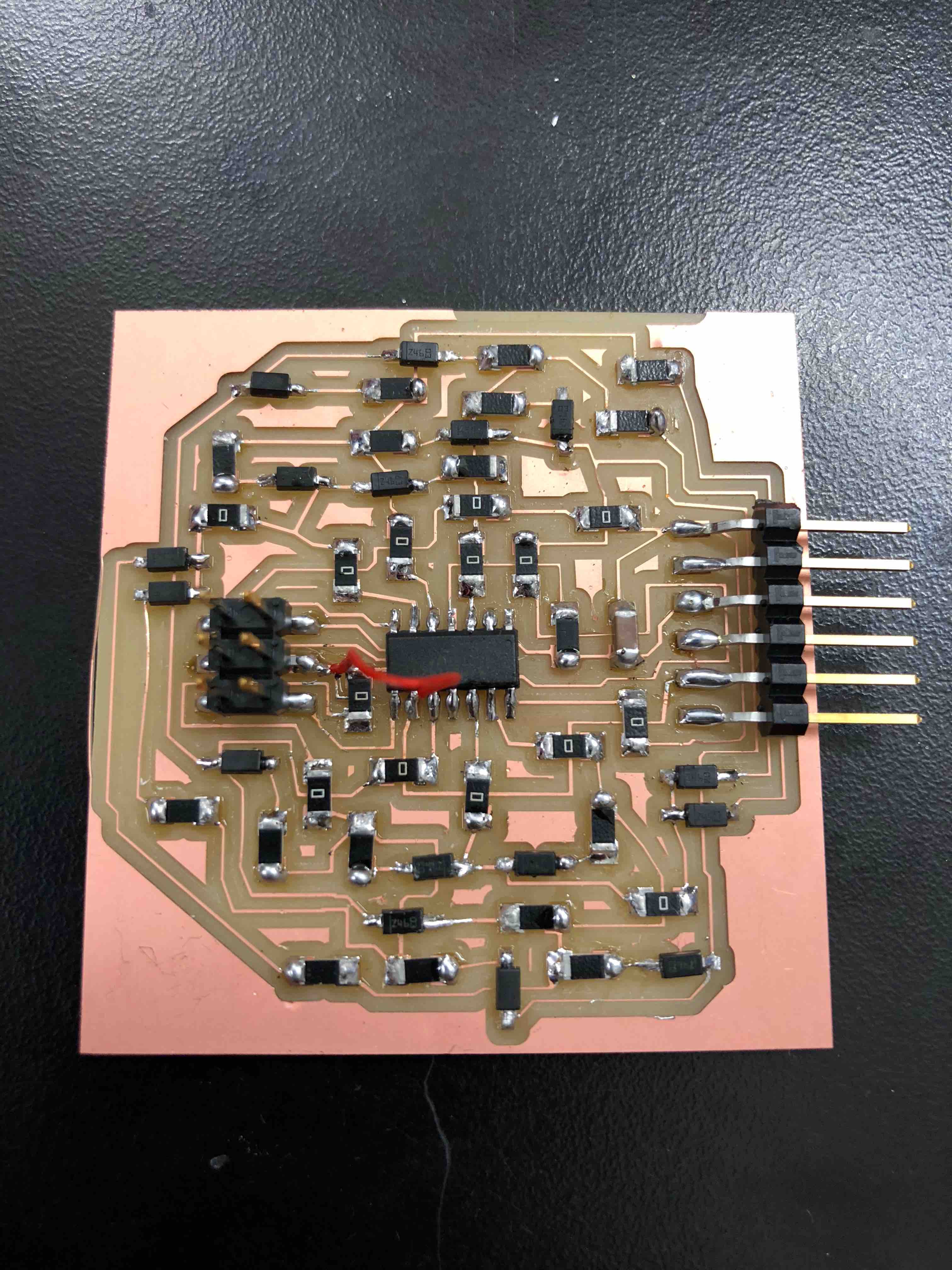
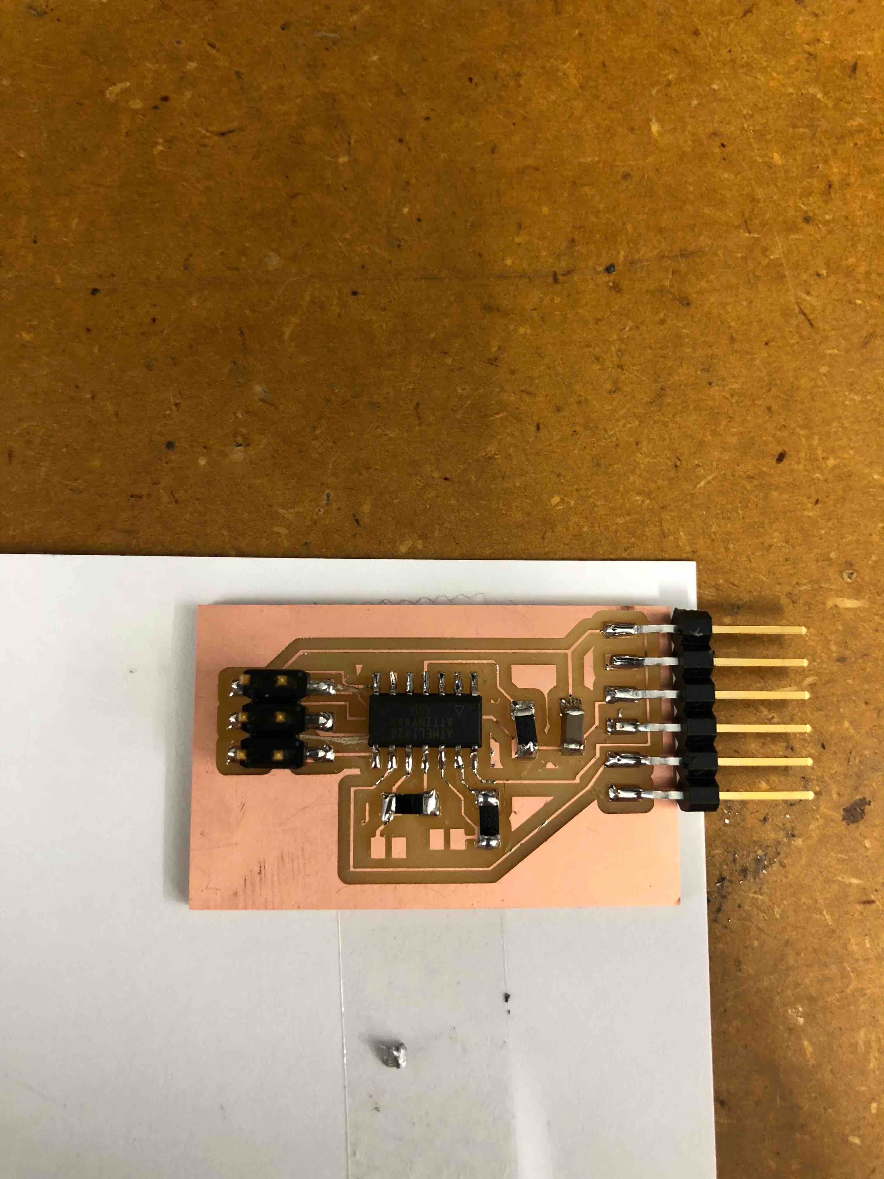
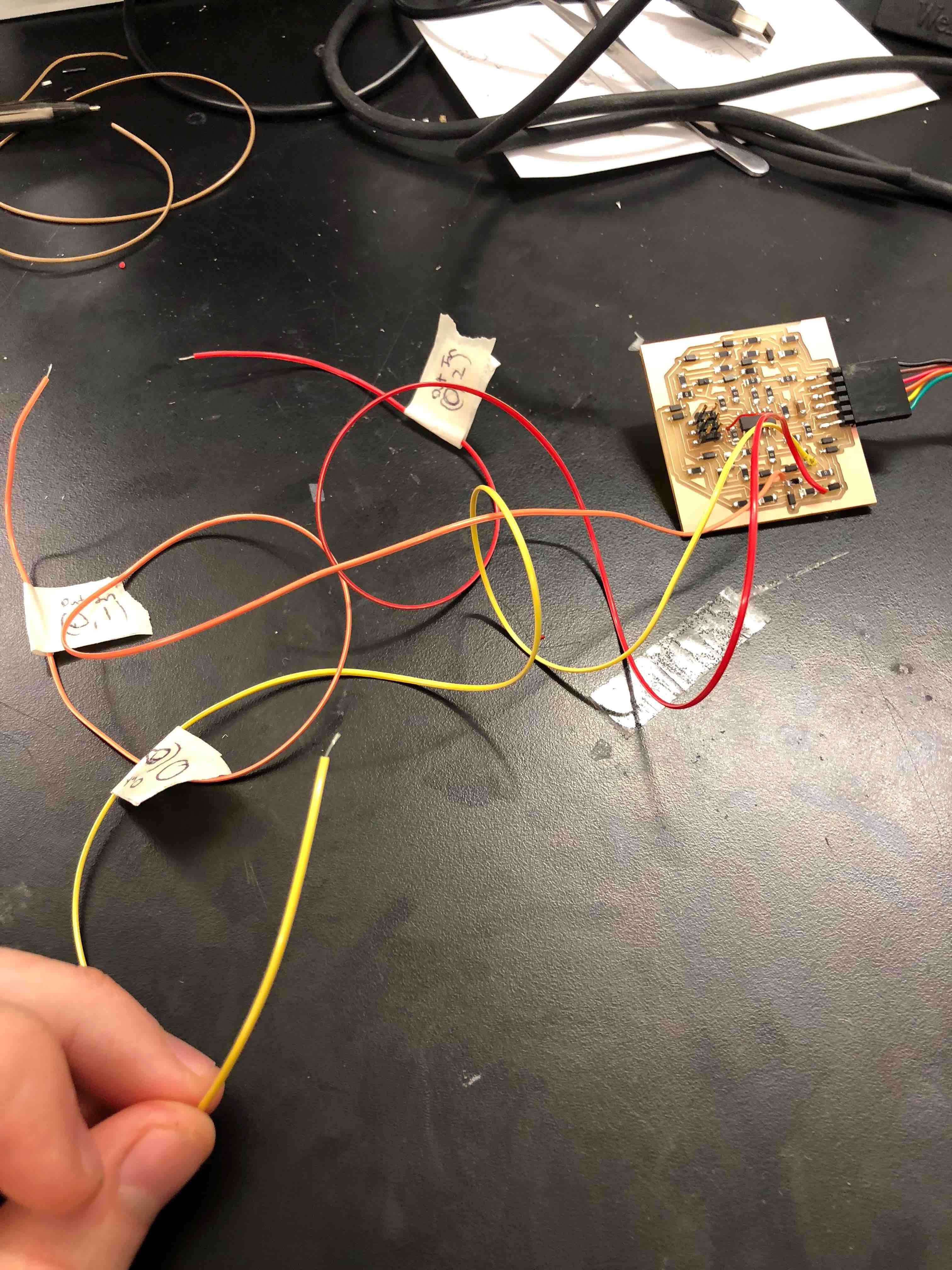
I got a lot of practice soldering this board. Above I solder the 0 Ohm resistors, the diodes, and then the 1M Ohm resistors, FTDI, ISP, a 10k Ohm resistor and a 1uF capacitor. I then attach a wire to the ground side of each 1M Ohm resistor. These wires will eventually be connected to each square of the board. To keep track of which wires were which, I taped small tags on them that had the input and output pins on them, as each sensor has a specific input pin and output pin. With 4 of each I was able to get 16 wires for 16 sensors, where each of these boards could service a quarter of the chess board.
In the interest of saving time I cut a 18"x18" piece of low quality wood with a scroll saw. I designed the electrodes in Fusion 360 for each square to be 2"x2" so there would be an inch border on the board. I vinyl cut 16 of these electrodes and then placed them on the board. The design is a square with a circle on the inside, with an empty ring separating the center circle of the electrode and the outer square. The piece placed on the board would have a base wide enough to cover both the central electrode and the ground square, making a more consistent capacitive loading sensor. The square would be connected to ground and the circle to one of the sensors.
I wired each of the sensors into the board and tested them out and I was able to get a signal for each electrode. The next steps are to network three more boards so I can cover 64 squares, and to 3D print the pieces and measure their capacitive loads so I can code in what will allow the GUI to identify the pieces.
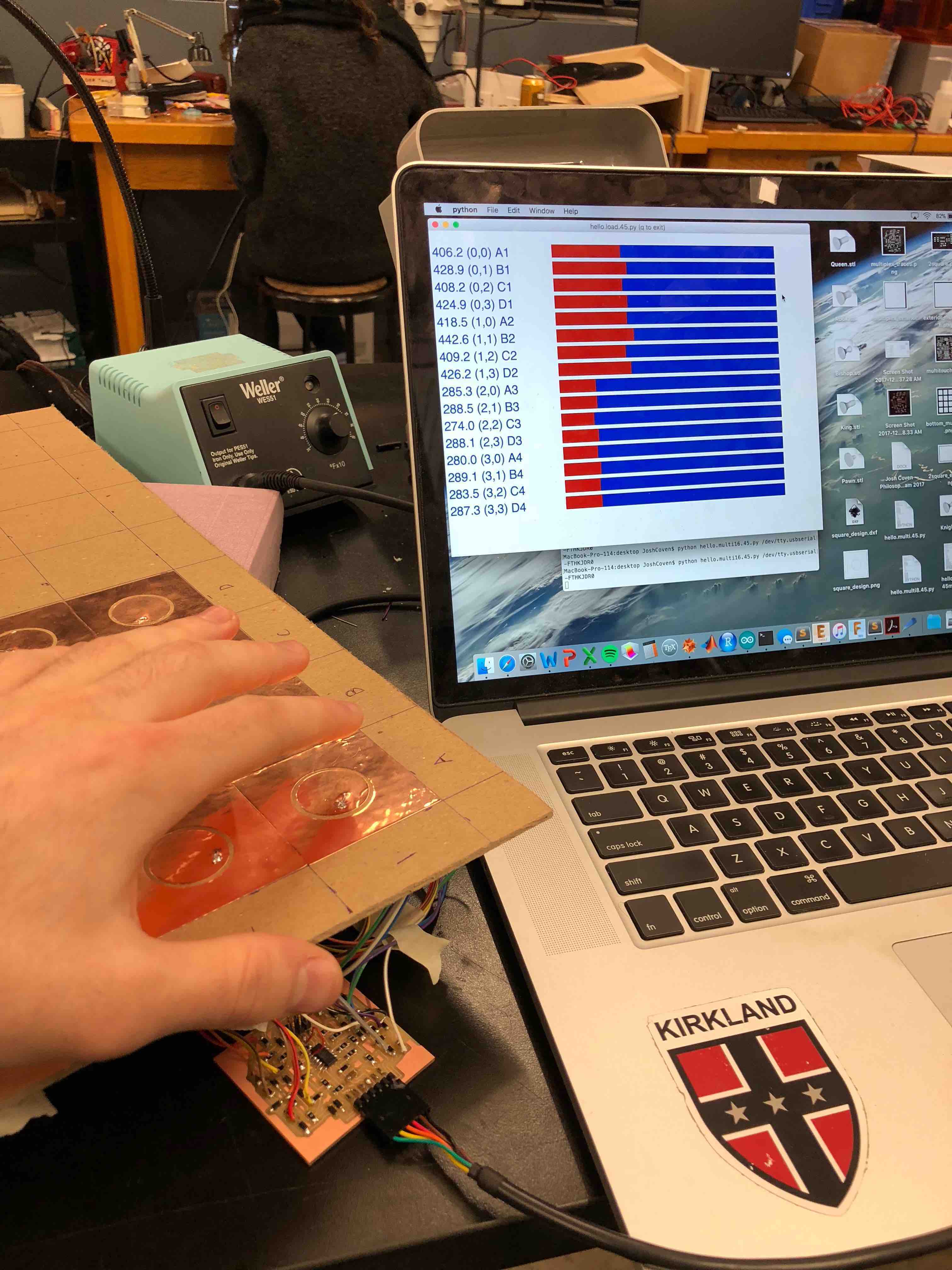
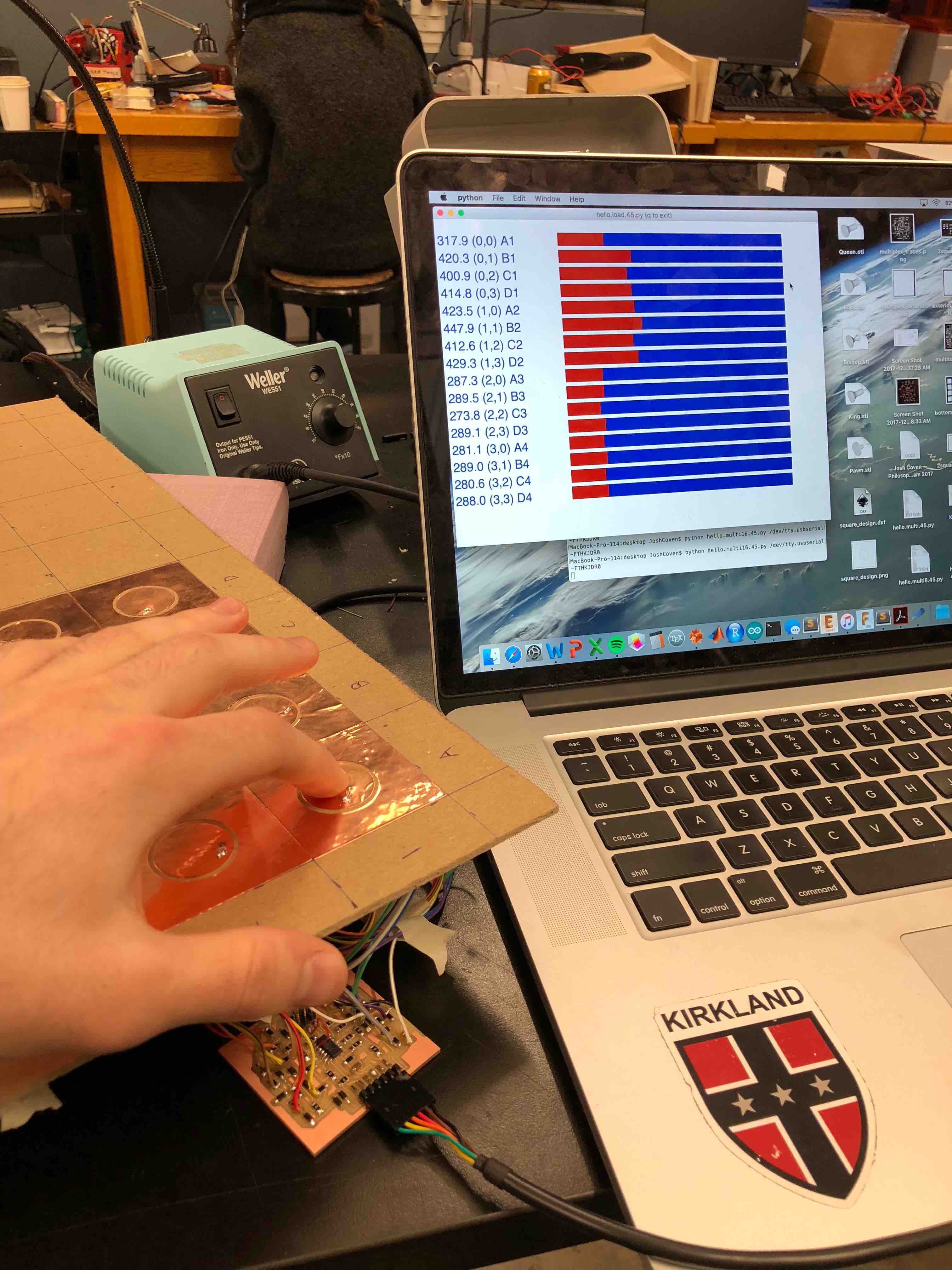
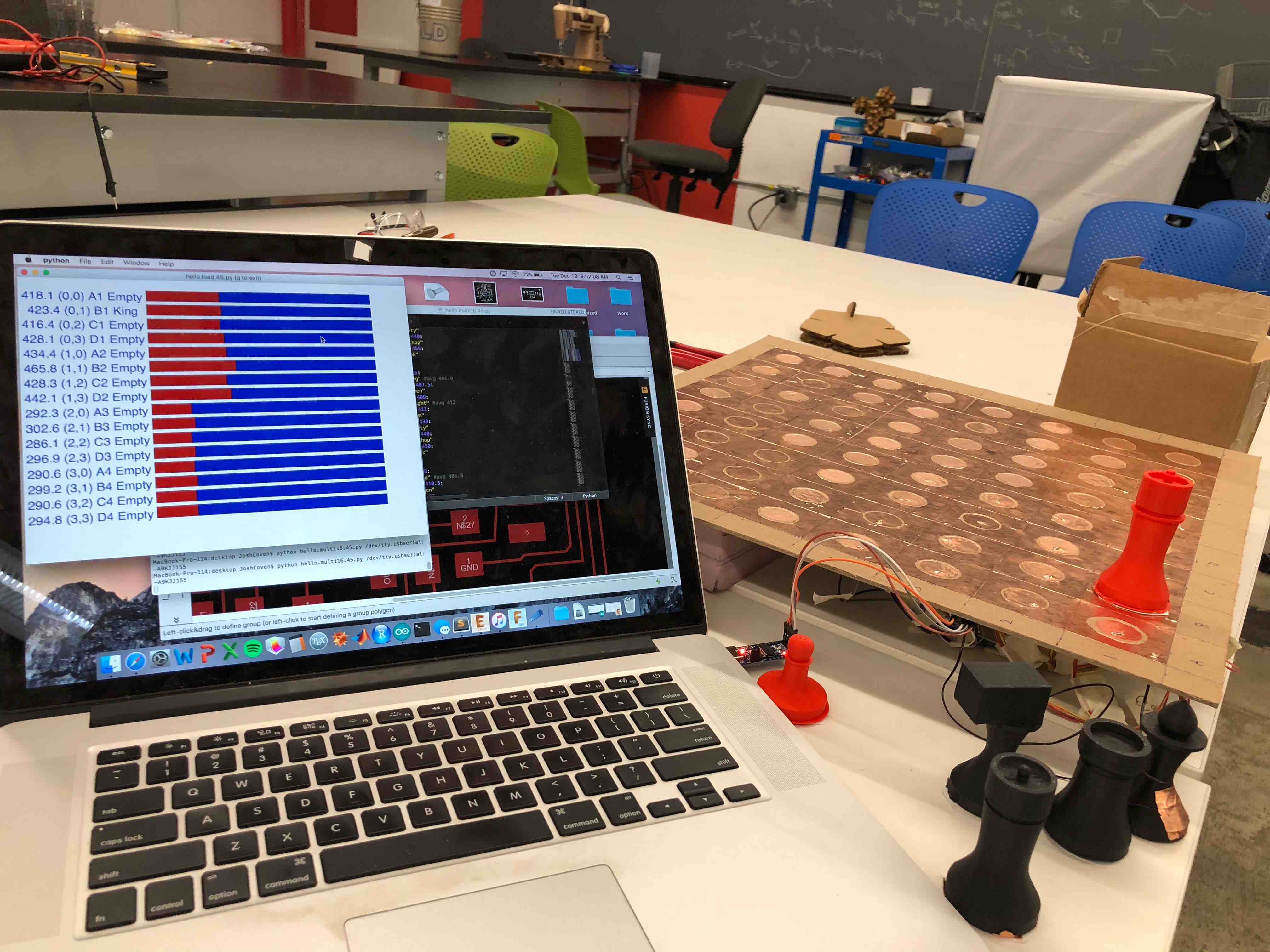
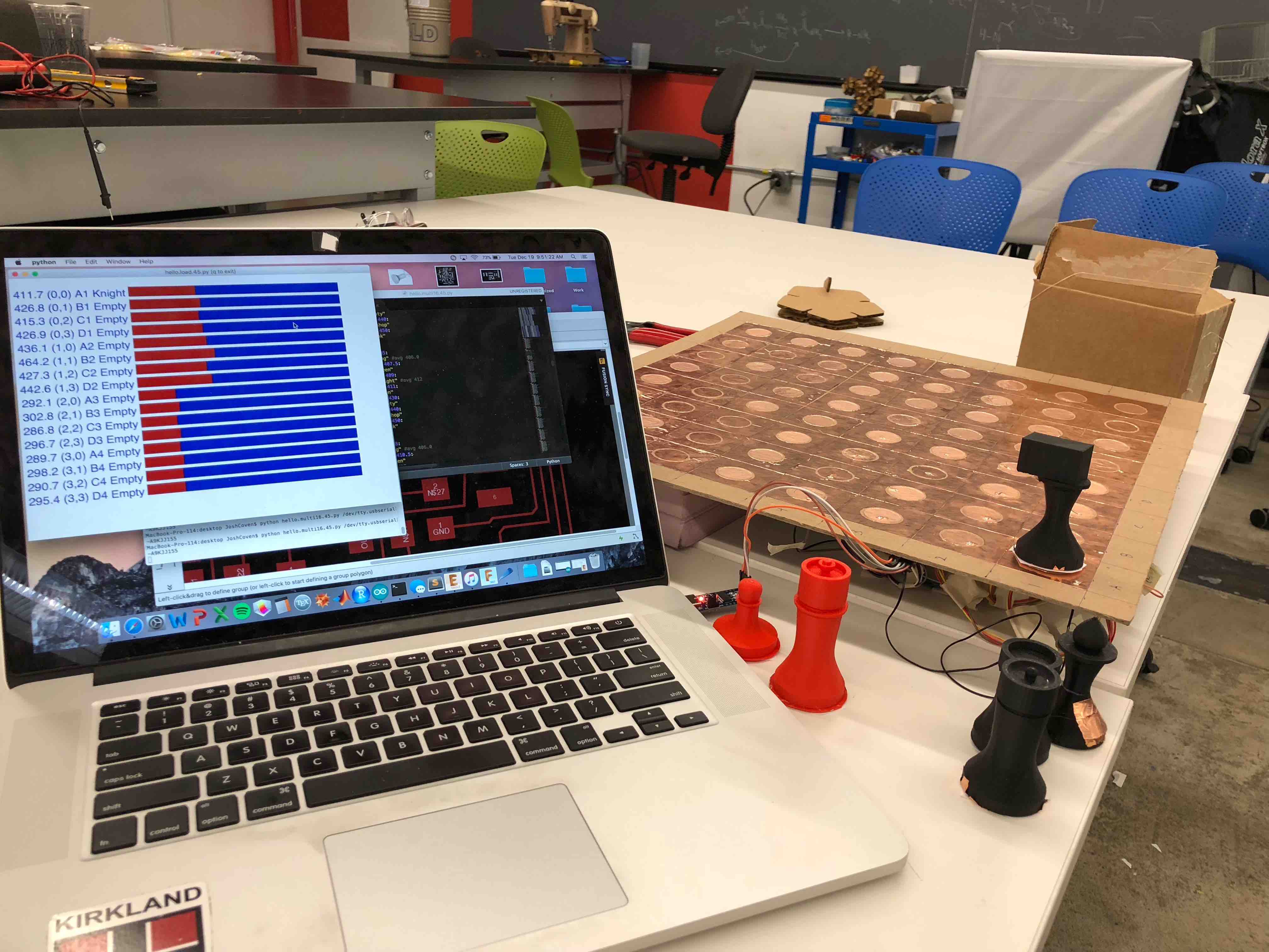
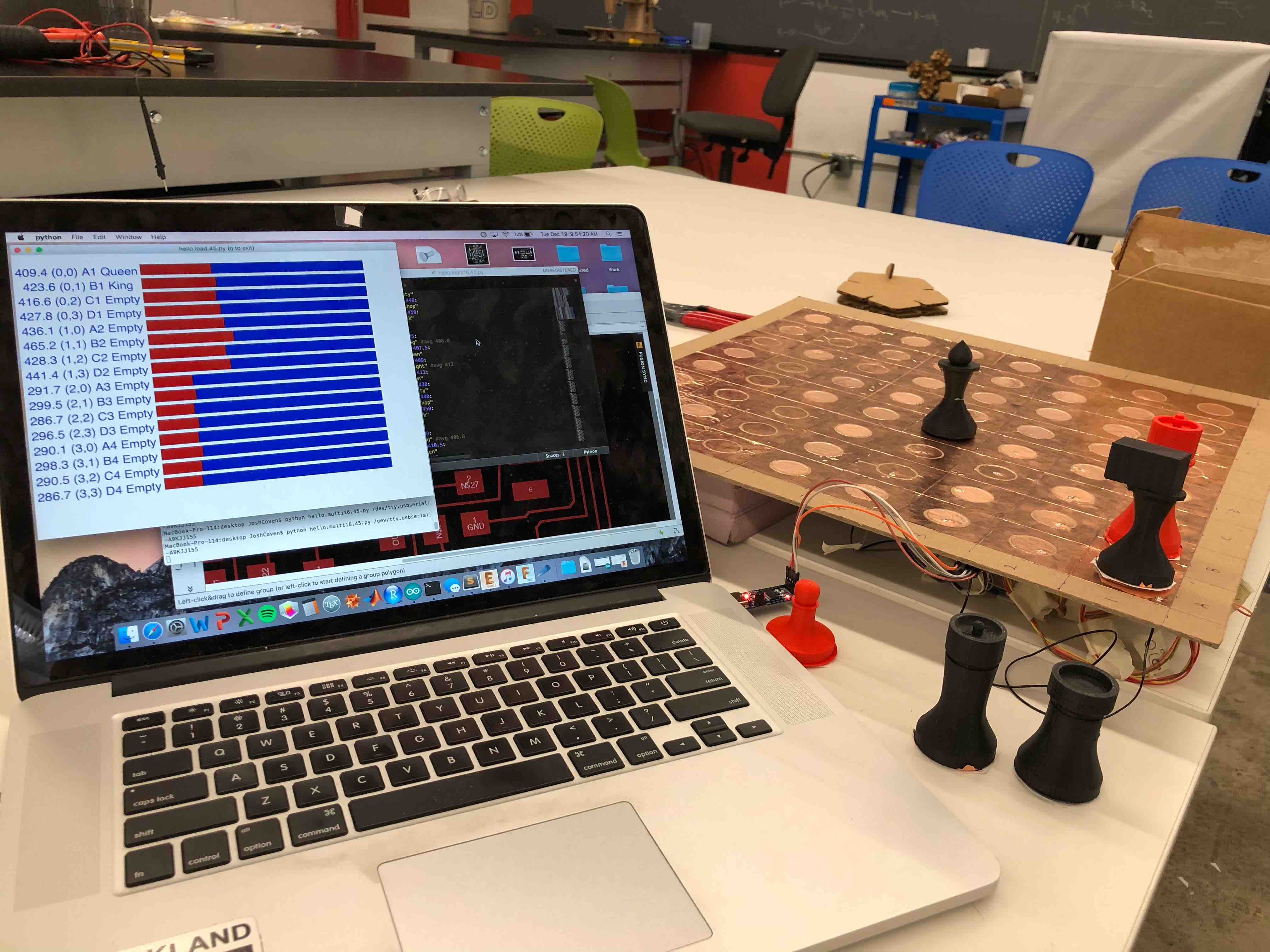
I designed each chess piece using Fusion 360 and then 3D printed them in the Sindoh Wox. I tested them on the board and found that even with altering the pieces by adding copper and paper to the base to change their capacitive load, the variation of the capacitive loads of the pieces was small. The GUI is designed to have the value from the Hello Loading example for easy observation, the output and input pins on the board, the chess square, and the piece occupying it.
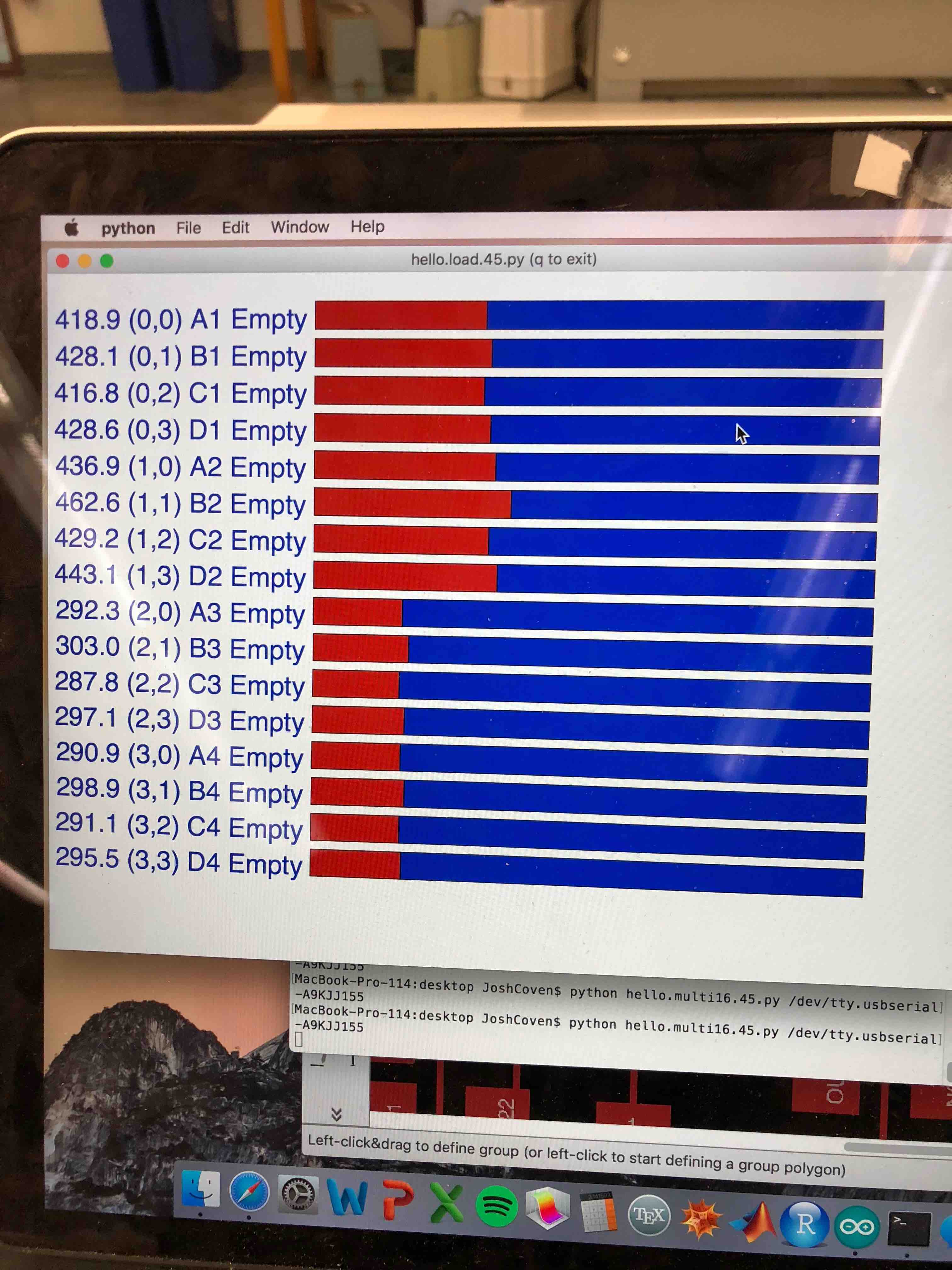
I could only get the board to recognize empty squares and a couple different pieces, not the 13 different states required to sense pieces of both colors and empty squares. There were also significant cross effects due to the small variation between the pieces. Placing a different piece on a far away square could change the capacitance of another square by enough to change the reading of a different square.
So there are three remaining issues: cross effects, networking, and capacitance variation of the pieces. I will continue to work on these.