
Week 8 Input devices
As part of my final project, I wanted to be able to detect angle of bending. For that, I could use a sensor input device (bend, strain or pressure)
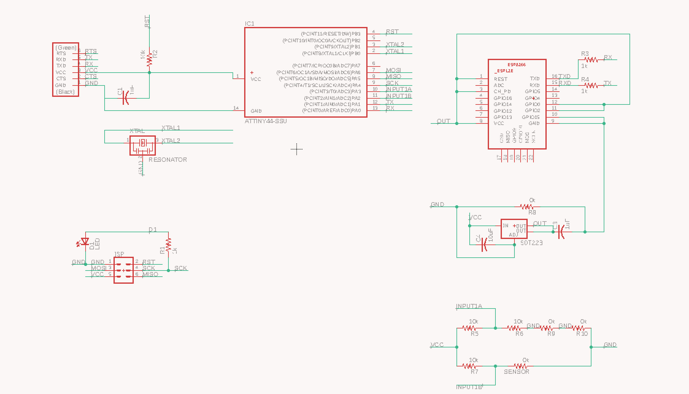
I designed the board below for input. It adds the sensor as one leg of a Wheatstone bridge:

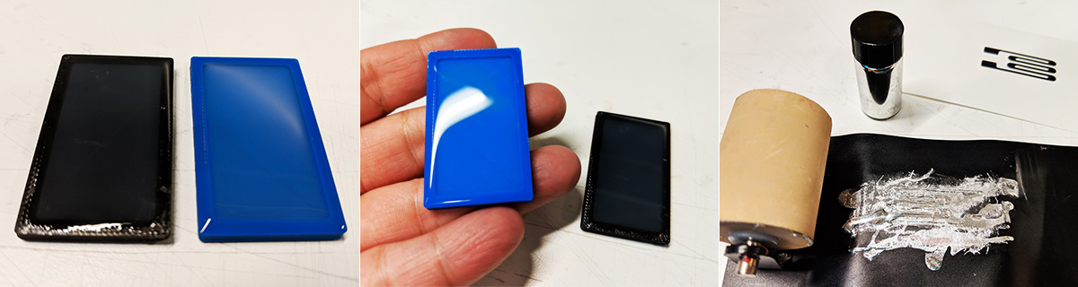
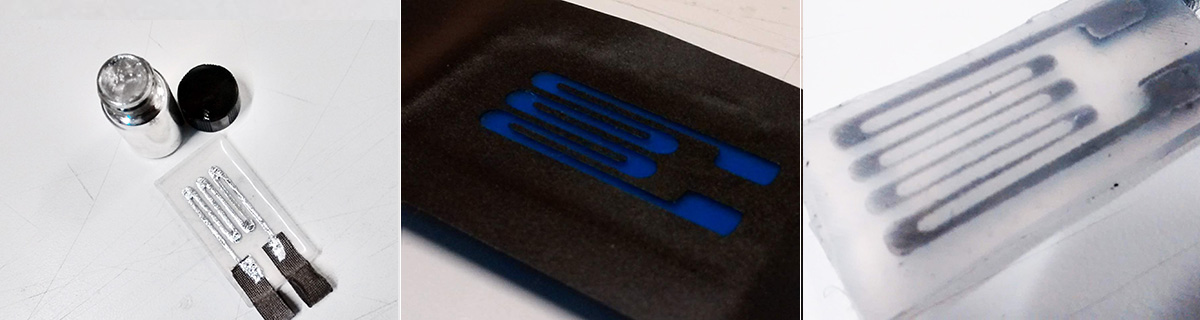
Because I was trying to build a stretchable device, I started to play around with methods for fabricating my own sensor. I tried two different methods for a custom sensor. The first one was to cast 5 layers of silicone and conductive fabric, this way:
1 - silicone
2 - conductive fabric (shiny side face down)
3 - silicone
4 - conductive fabric (shiny side face up)
5 - silicone
You don't need a special mold for this, but that can help. In my case, I made a piece larger than the desired sensor and used a laser cutter to cut the sensor pieces the size I wanted them to be.
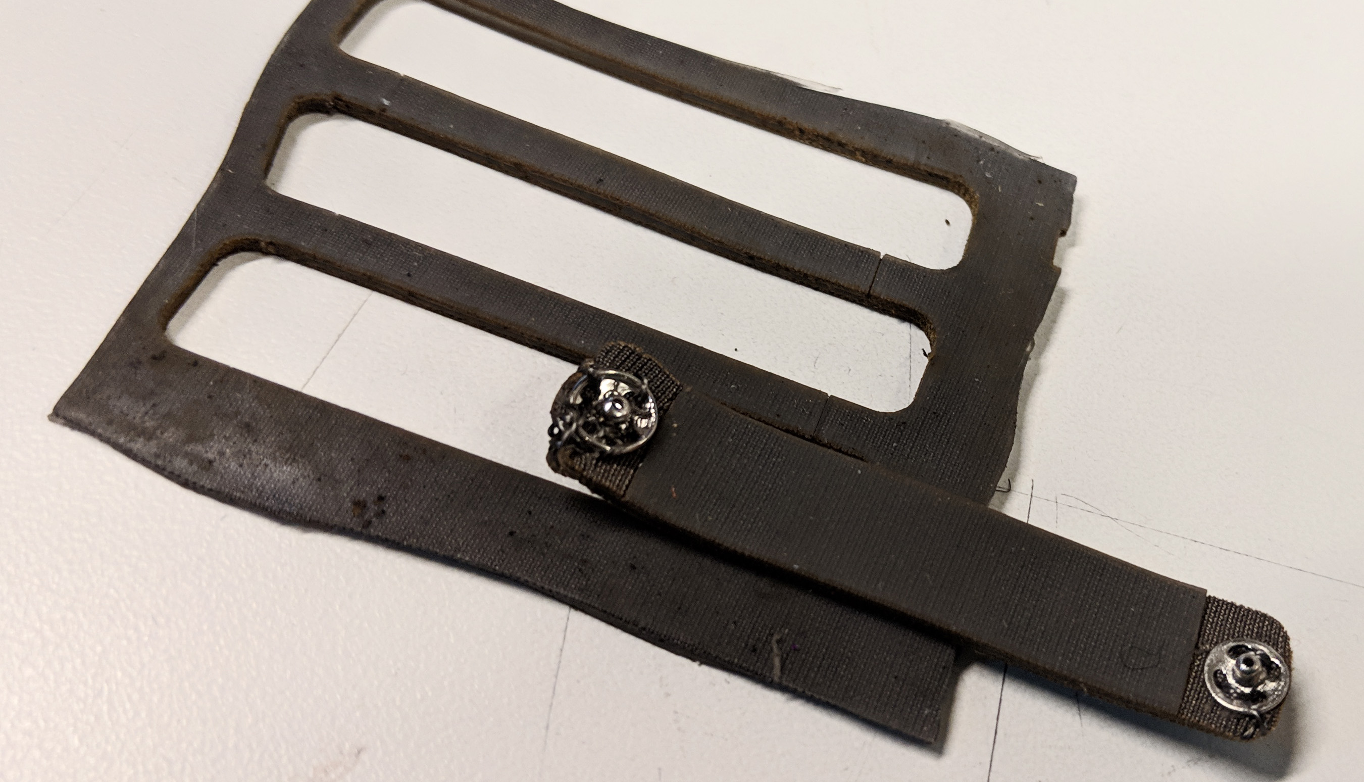
Another test that I did was to use liquid metal, galinstan, for the conductive traces. It has the ability of "healing" itself, making it usable for stretchable electronics. I have been interested in working with it for some time, and wanted to test a DIY method of fabrication of silicone devices. I had success in one of my masny tests for using a pattern for the strain sensor, but the previous method generated a better result.
 <
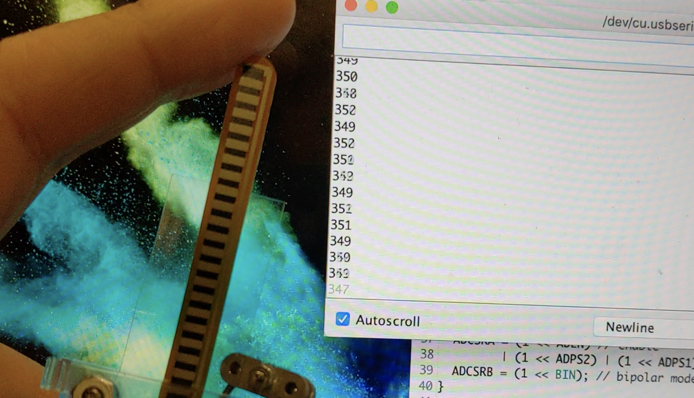
<For getting the sensor values, I used the ADC pins of ATtiny44A in differential mode with gain. The bend sensor worked well with that code and bridge, but the custom sensor was varying too much from measurement to measurement. I need to check if this was a flaw in the way I made the connections from stretchable to hard connections, or something else. Here's the code for using ADC pins in differential mode:
        /* admux */
  ADMUX = (0 << REFS1) | (0 << REFS0) // 5V ref
        | (0 << ADLAR) // right adjust
        | (0 << MUX5) | (1 << MUX4) | (0 << MUX3) | (0 << MUX2) | (0 << MUX1) | (1 << MUX0); // 20x gain

  ADCSRA = (1 << ADEN) // enable
         | (1 << ADPS2) | (1 << ADPS1) | (0 << ADPS0); // prescaler /64
  ADCSRB = (1 << BIN); // bipolar mode
In ADMUX, the third line corresponds to the binary code given in the datasheet (in my case, I had PA2 as positive and PA3 as negative inputs, so the high/low code was 010000 (x1 gain) or 010001 (x20 gain). Put each of these zeros and ones separately: | (0 << MUX5) | (1 << MUX4) | (0 << MUX3) | (0 << MUX2) | (0 << MUX1) | (1 << MUX0);.
Here's the full code I used. I would implement an average for the final code, to smooth out the signal.
#include <SoftwareSerial.h>;

#define RX    0   // *** PA0, Pin 13
#define TX    1   // *** PA1, Pin 12

long inputRaw;

SoftwareSerial mSerial(RX, TX);

void setup()
{
  TCCR0B = TCCR0B & 0b11111000 | 1;
  TCCR0A &= ~B11;
  TCCR0A |= B011;

  // ***
  // *** Initialize the Serial port
  pinMode(RX, INPUT);
  pinMode(TX, OUTPUT);

  mSerial.begin(9600);
  mSerial.println("Initializing serial...");

  analogReference( DEFAULT );

  /* admux */
  ADMUX = (0 << REFS1) | (0 << REFS0) // 5V ref
        | (0 << ADLAR) // right adjust
        | (0 << MUX5) | (1 << MUX4) | (0 << MUX3) | (0 << MUX2) | (0 << MUX1) | (1 << MUX0); // 20x gain

  ADCSRA = (1 << ADEN) // enable
         | (1 << ADPS2) | (1 << ADPS1) | (0 << ADPS0); // prescaler /64
  ADCSRB = (1 << BIN); // bipolar mode
}

void loop()
{
  /* get input */
  ADCSRA |= _BV(ADSC); // Convert
  while (bit_is_set(ADCSRA,ADSC));
  inputRaw = ADCL;
  inputRaw |= ADCH<<8;

  mSerial.println( inputRaw );

  delay(200);
}