Tracking page Final Project
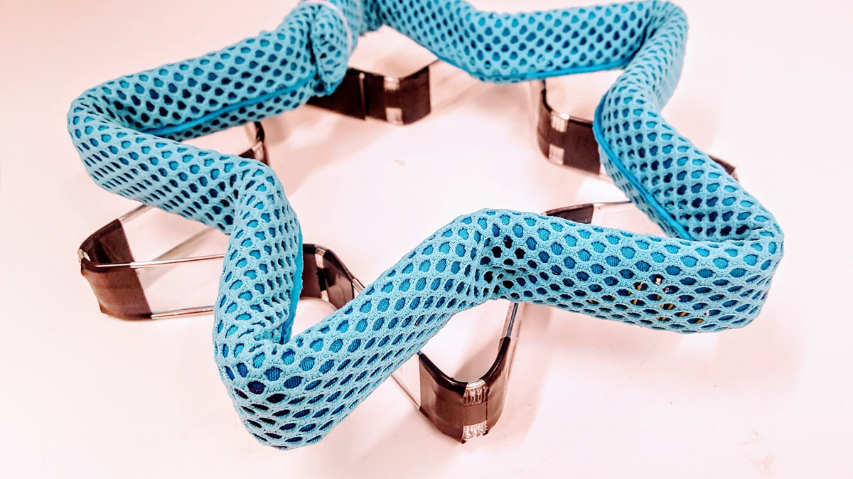
I am working on a deformable controller that can be bent by the user into different shapes. These shapes are sensed and create variations of digital outputs. If the output is sound, for example, it can be a shape shifting digital instrument, whose sound qualities change according to the shape: a circle is a drum, a star sounds like wind chimes. A previous version of this that I have built, using acryllic, comercial boards and hand-sewn sensors, was too fragile and had many limitations. Especially because I want to learn more about making electronics, I would like to rethink the structure with custom-made armature, sensors and board.
Rigs / Armature
I have been thinking about the possibility of expanding the idea to make more complex shapes. For this, I need to build a structure that is light enough to be manipulated, allows sensing of joint angles, but can be posed and keep the desired shape.
Because I have a particular interest in sculpture, one of the things that came to my mind was to use custom rigs similar to those made for stop motion.
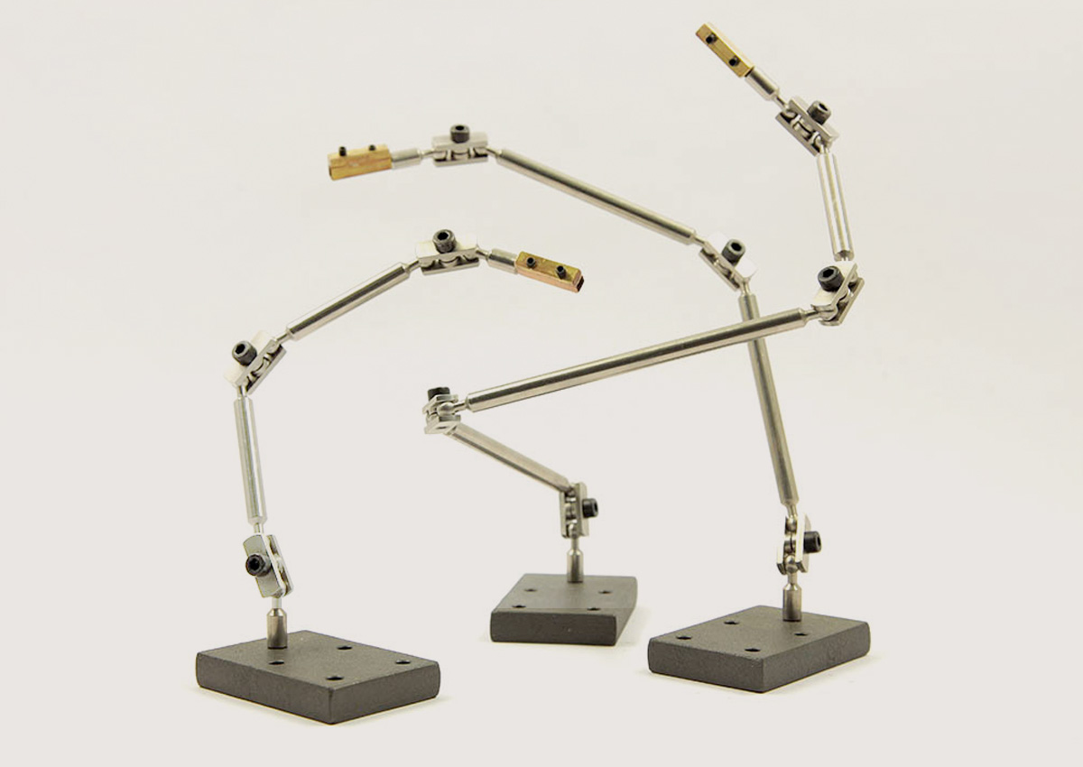
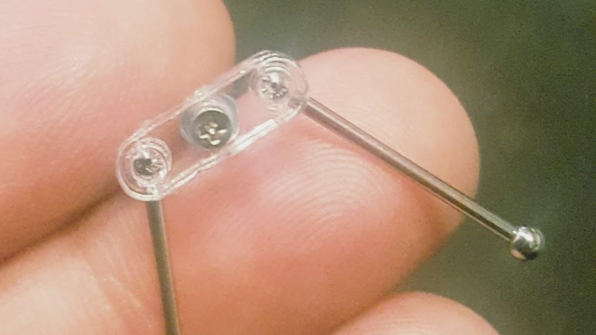
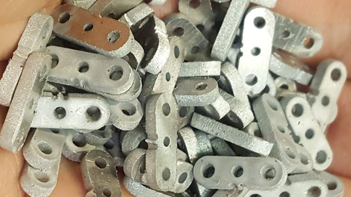
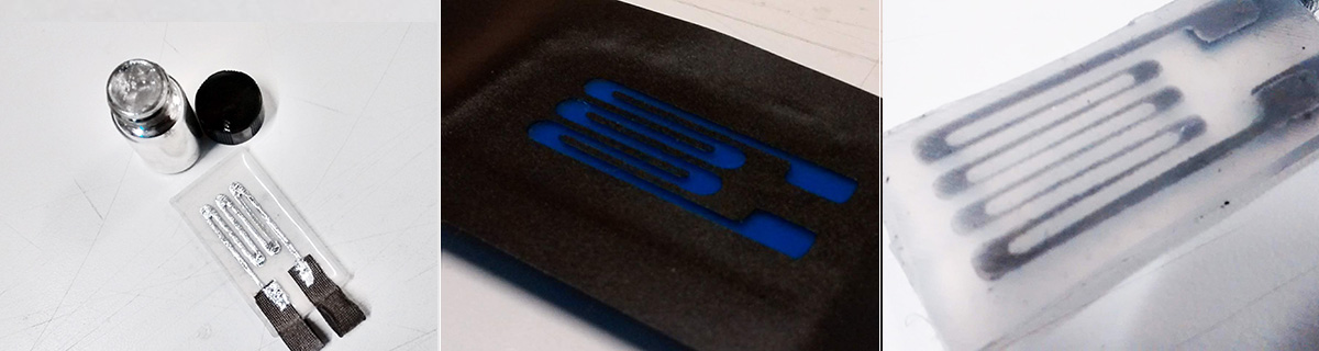
Commercially available stop motion parts and big and expensive, so I thought of trying to build my own. My first try using acrylic and theaded balls showed me the sizes and allowed me to experiment with motion before cutting metal parts. Of course acryllic was very brittle, and in my second try I cut the parts in metal using the waterjet.
Sensors
The sensors I made in my first try were inspired by Hannah's Neoprene bend sensor. I had trouble with the fragility of these sensors, which did show variation but not enough precision to allow me to measure angles. I had these connected through a simple voltage divider.
The sensors are the crucial part of this project. The device needs to have stretchability and accuracy, so I'm spending time with it. In the last week I tried a method of sensor fabrication with conductive fabric and silicone which seems promising to avoid the problem of the fabric wearing out or losing it's conductivity.
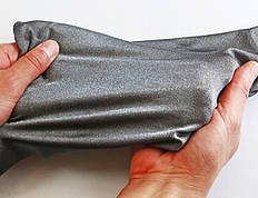
The fabric is medical grade silver coated 76% Nylon, 24% elastic fiber fabric.
- Shielding performance: 30-50 dB, tested from 1-10 GHz
- Width: 135 cm wide (52 inches) but varies from lot to lot
- Weight: 4.3 oz/yd²
- Thickness: 0.40 mm
- Stretch: ~100% in length direction; ~65% in width direction
- Surface resistivity is < 1 Ohm/sq. (unstretched)
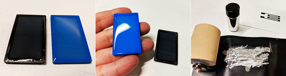
I used Ecoflex 30 and cast alternating dielectric and conductive layers (3 layers of Ecoflex and 2 layers of conductive fabric). A second test is to use a circuit stencil to "paint" a circuit onto dielectric silicone layer with liquid metal - galinstan (Gallium: 68.5%, Indium: 21.5%, Tin: 10%). This allow me to run wires through the surface, which can stretch without breakage. It's somethings similar to the example from Soft Robotics Toolkit website, but with a more DIY process.
Testing these samples with a multimeter I got a decent change of resistance, although at the small scale of hundreds of ohms. However I noticed the variation of resistance was not consistent on different measurements. I would like to continue developing on these custom sensors, but for the purpose of the class I tested the board with a bend sensor.
Board
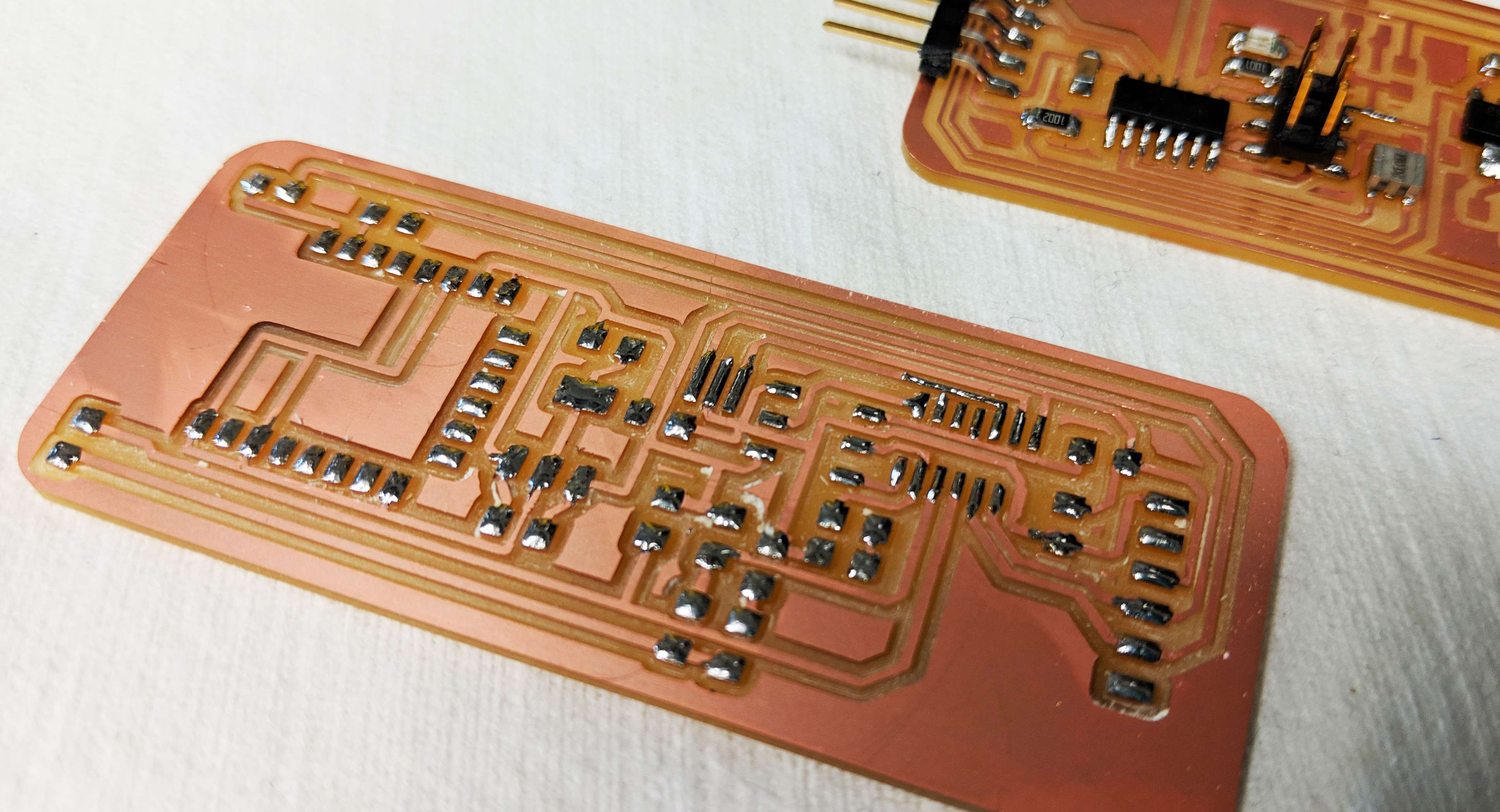
Initially, I also tried to build a stretchable board. I should probably have been less ambitious for the final project, since I am still learning the basic electronics, but I ended up spending a lot of time trying to work on a DIY process for stretchable electronics and unfortunately I couldn't get the components to stick to the silicone. Also, unless you use syringes on microchannels, the traces must the very thick so the component pads should also be a bit larger - at least .8mm in my tests, if you use the stencil method, but with syringes that could be as thin as .4mm
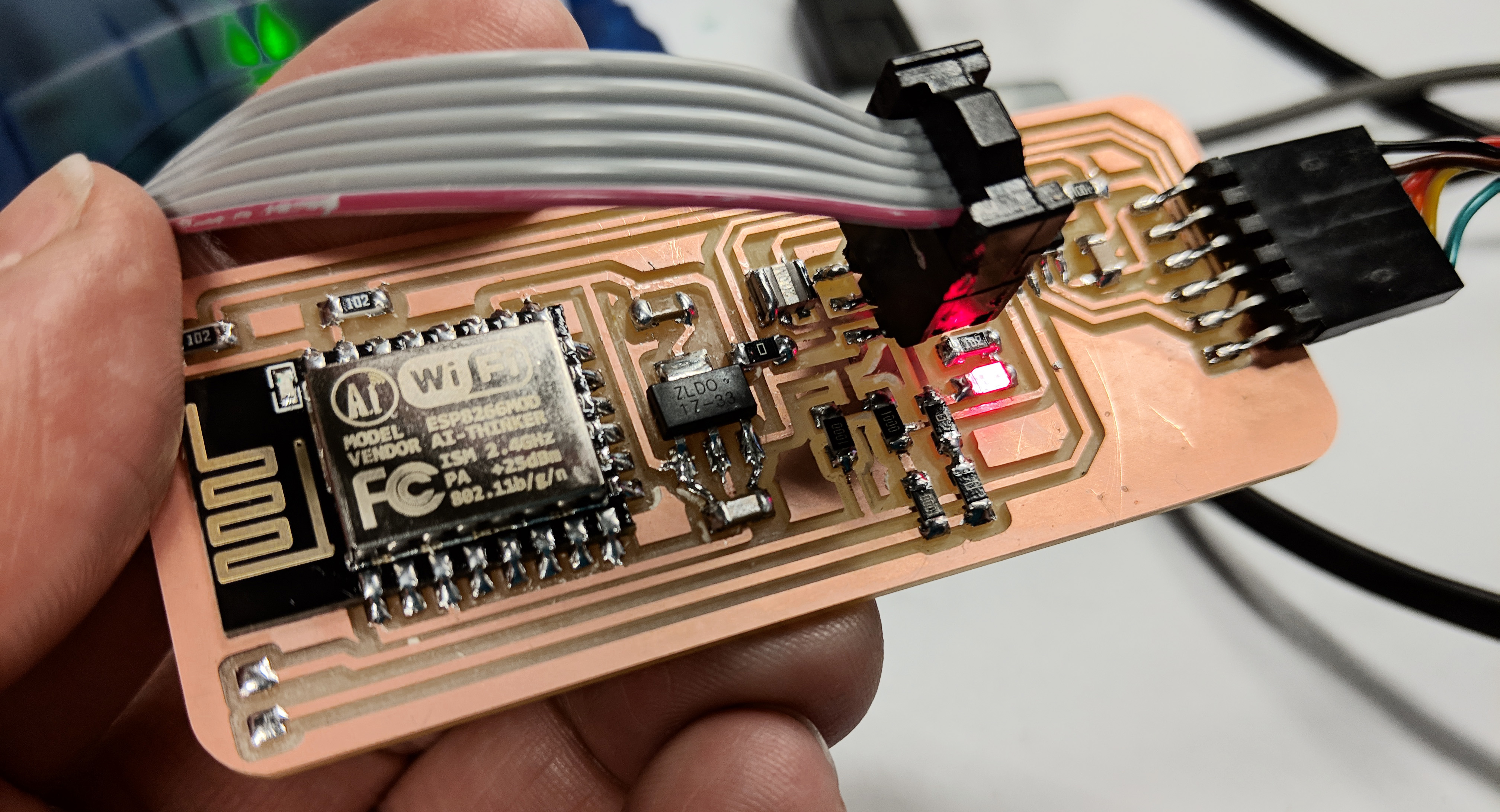
Building the board on Eagle took a lot more time than I expected. I was unsure about the configuration necessary for the sensor, and due to my inexperience in electronics, trying to make a board from zero was a big challenge. I spent quite some time studying bridges and op amps. It took me days to finish the schematic and the tracing because I really wanted to understand the connections. I had started out a board with the ATMega328p because I had the intention to use many sensors, but realizing I wouldn't be able to finish all of this until the project presentation, and after being informed that the ATtiny44A has builtin 20x amplifier for ADC, I decided to change the design for a simpler board so I could go on to the milling process.
After milling, after I had already started soldering, I realized I had forgotten to connect a few pads. I returned to Eagle and retraced them to finally solder the components.
Coding
To start out, with a slight fear that my board was still not correctly designed, I uploaded the most famous of all starters in electronics - Blink. It worked, yay!
Then I had a few more things to test. First, detecting the sensor as input. I was very confused with how to use ATtiny44A in differential mode. I had seen on page 146 of the ATtiny44 datasheet that it could amplify the sensor's voltage with gain of 1x or 20x. But where to put the bits indicated in my code? Thankfully with the help of other students I understood that this part of Neil's temperature sensor code was the crucial one for ATtiny (I adapted it for the ATtiny44A) and for the pins I was using):
        /* admux */
  ADMUX = (0 << REFS1) | (0 << REFS0) // 5V ref
        | (0 << ADLAR) // right adjust
        | (0 << MUX5) | (1 << MUX4) | (0 << MUX3) | (0 << MUX2) | (0 << MUX1) | (1 << MUX0); // 20x gain

  ADCSRA = (1 << ADEN) // enable
         | (1 << ADPS2) | (1 << ADPS1) | (0 << ADPS0); // prescaler /64
  ADCSRB = (1 << BIN); // bipolar mode
In ADMUX, the third line corresponds to the binary code given in the datasheet (in my case, I had PA2 as positive and PA3 as negative inputs, so the high/low code was 010000 (x1 gain) or 010001 (x20 gain). Put each of these zeros and ones separately: | (0 << MUX5) | (1 << MUX4) | (0 << MUX3) | (0 << MUX2) | (0 << MUX1) | (1 << MUX0);
At this point I was late and super tired, but went on to test the Wifi communication with the ESP8266, which would send the sensor data. The AT commands were not bringing any response or error, so it took me many hours looking for mistakes in code, when I realized I had switched RX and TX on the board. On no! It was too late to remake the board, so I will have to finish that in the future...
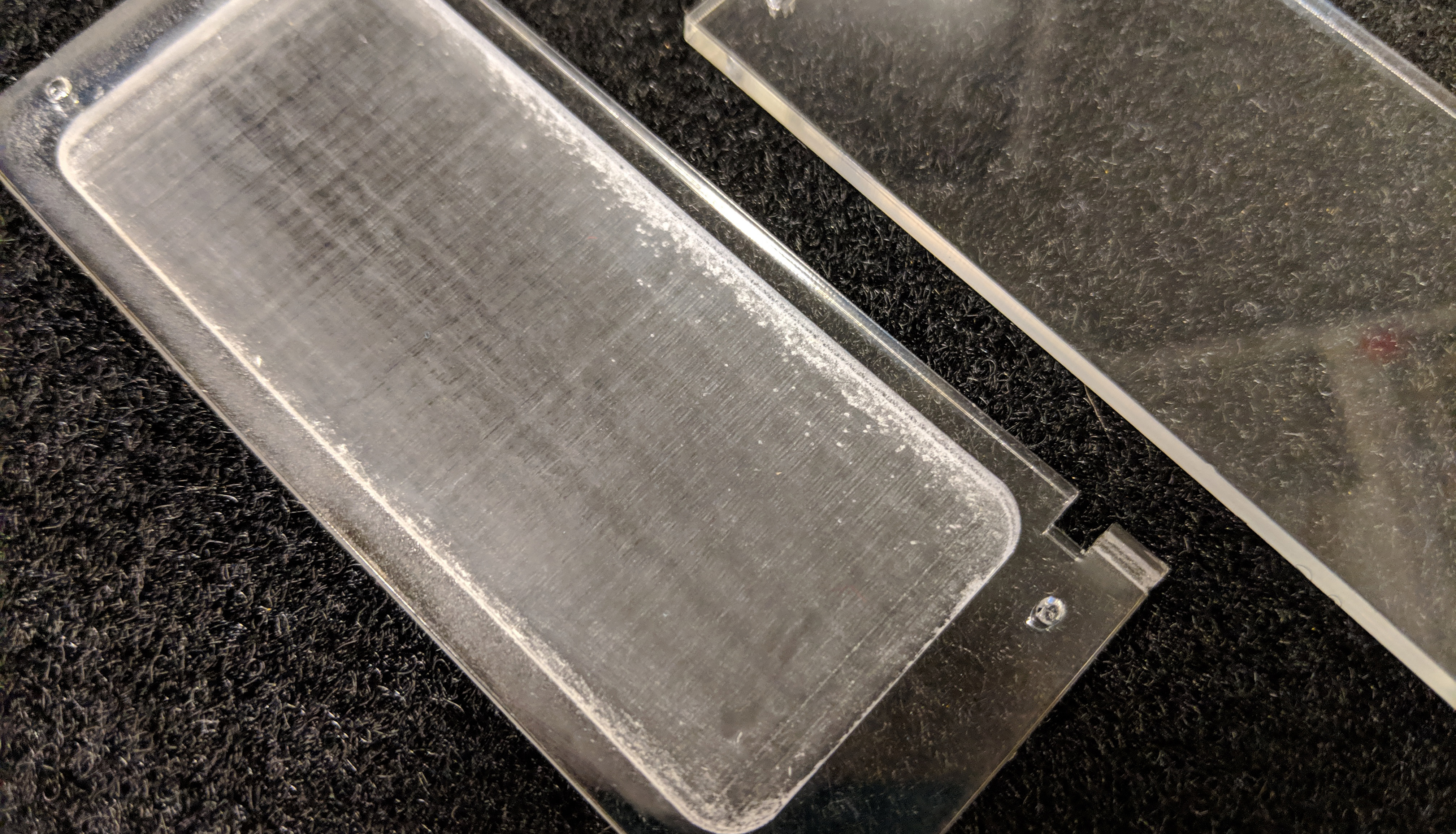
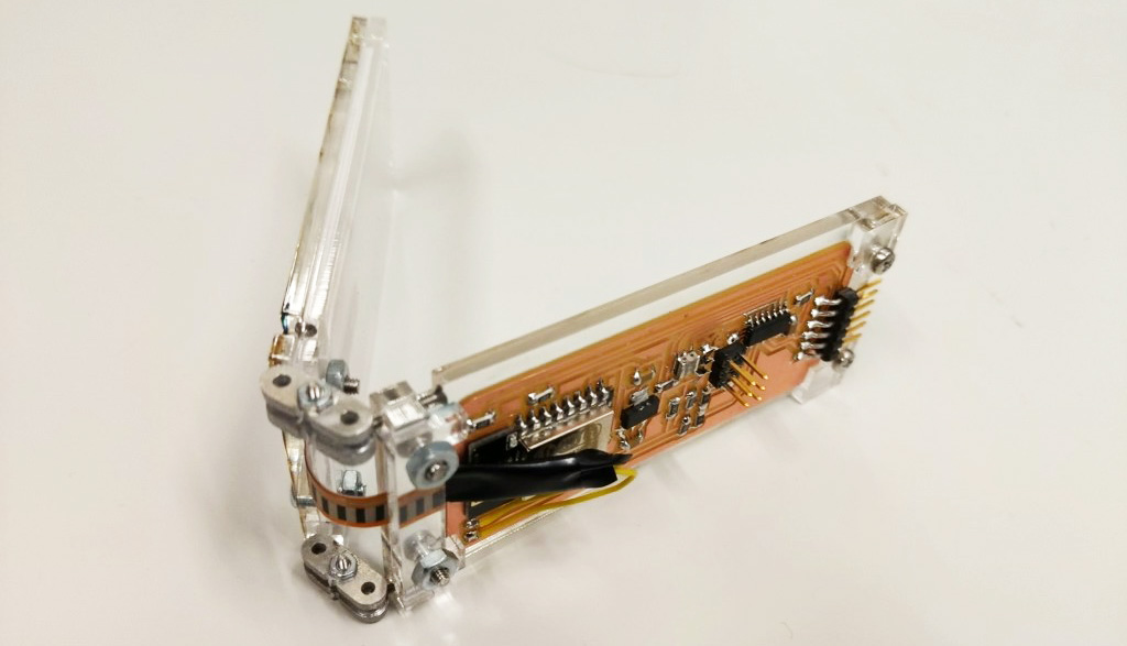
Acrylic case
To put everything together as one joint of my future complete controller, I laser cut a case in clear acrylic, etching the acrylic to acomodate the board between two plates and adding holes for screws. The stop motion joints did not work so well for this purpose, I will have to think of a different posable joint.