Puzzle modules
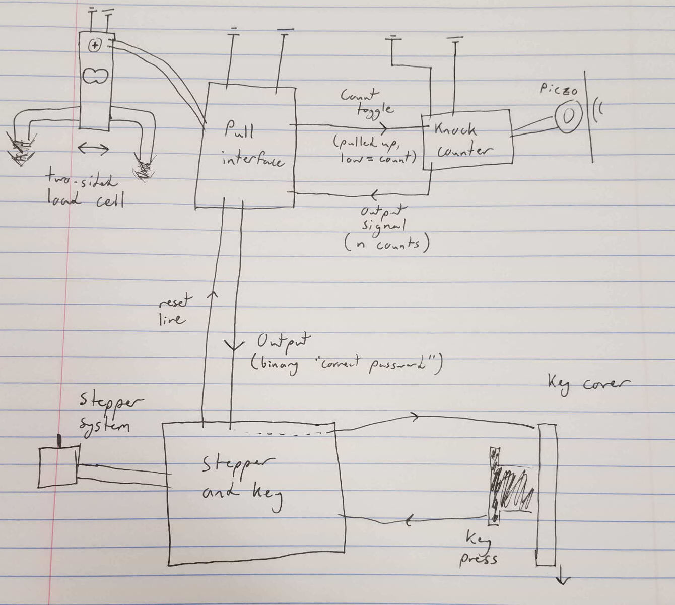
For this week, I started work on connecting the components for my final project. In the final box, everything will be wired, but I'll have a couple different microcontrollers to keep track of different steps of the puzzle. In week 8, I started my knock counter board. For this week, I finished it, and tried to connect it with a board that keeps track of the knocks counted, which will pass on a signal to the next step if all digits of the password are correct. To see the knock board before I networked it, check out week 8.
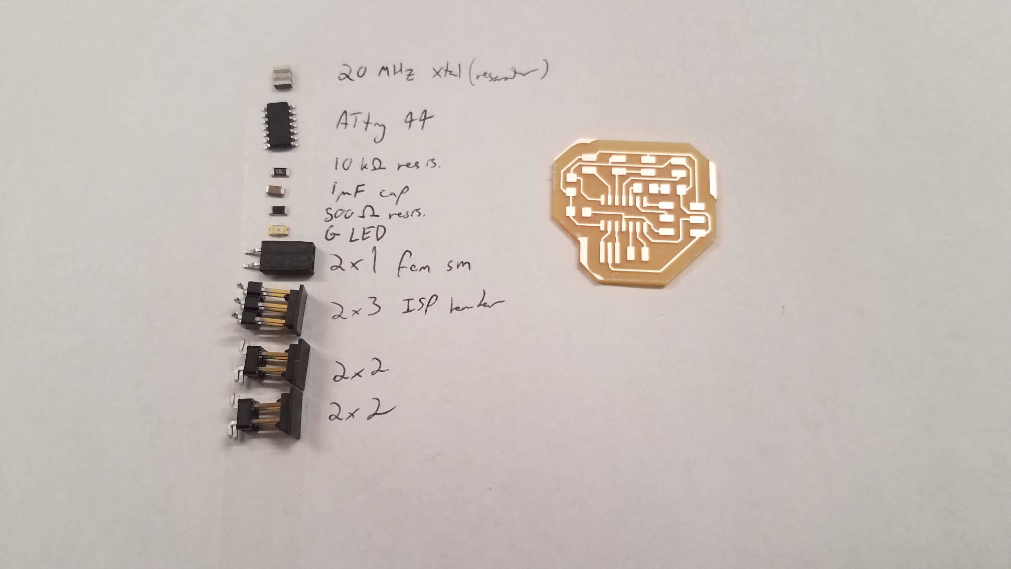
Getting the knock board to work took up a lot of my time. Once I had it, I put together the password board, and tried to write some simple code for it.
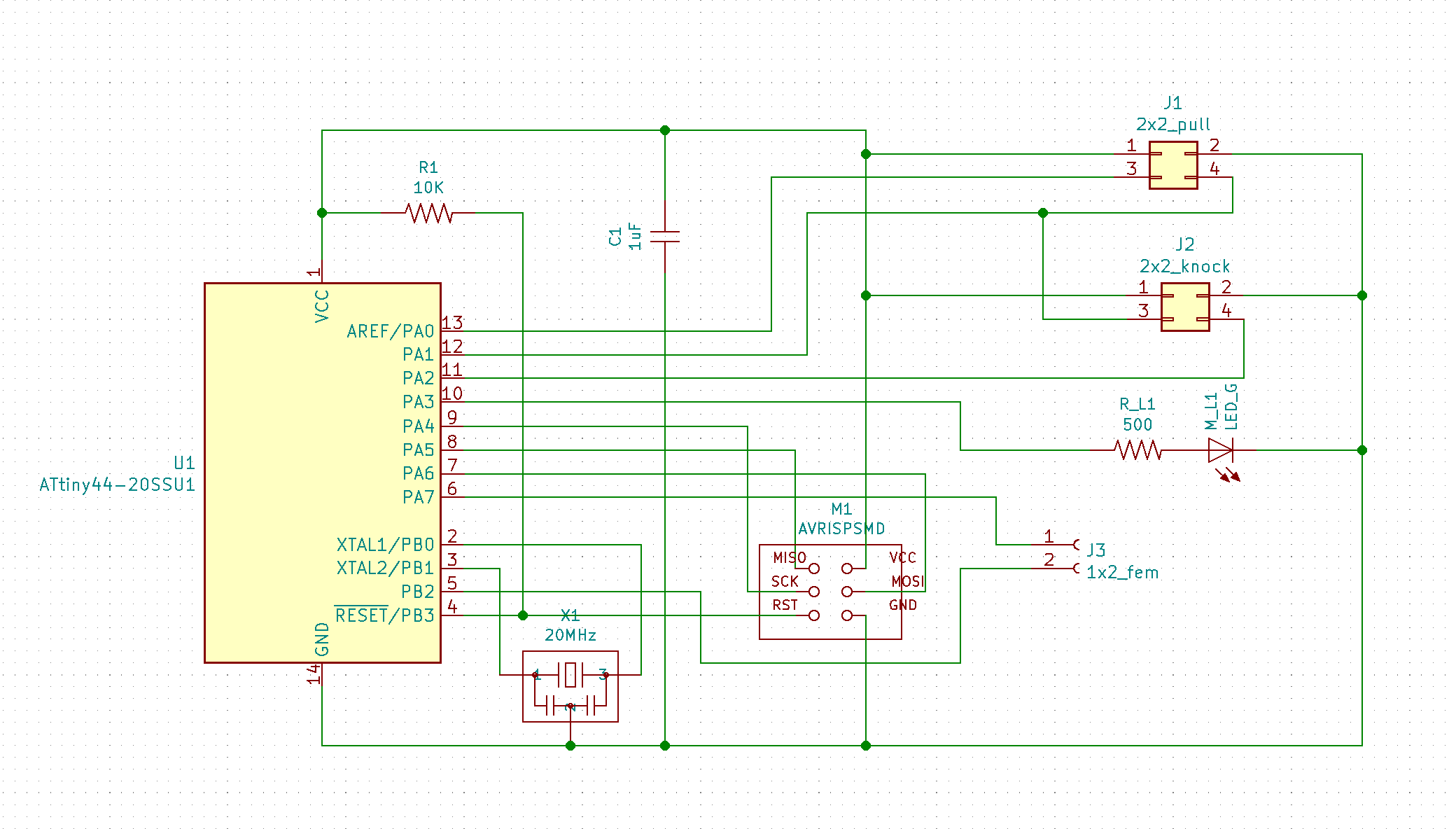
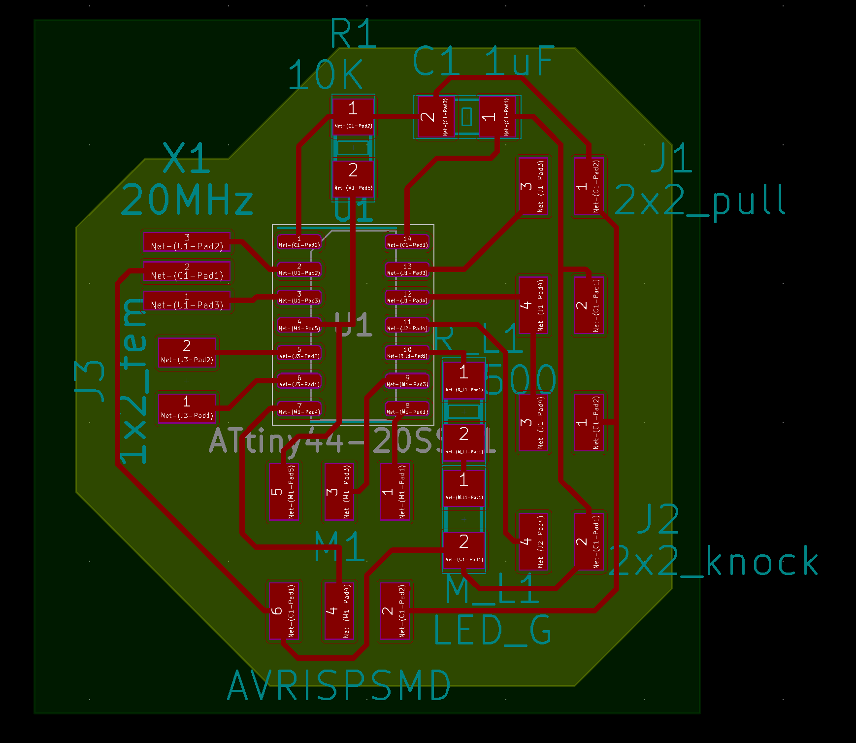
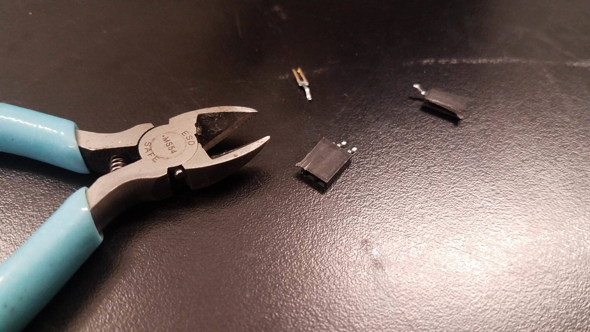
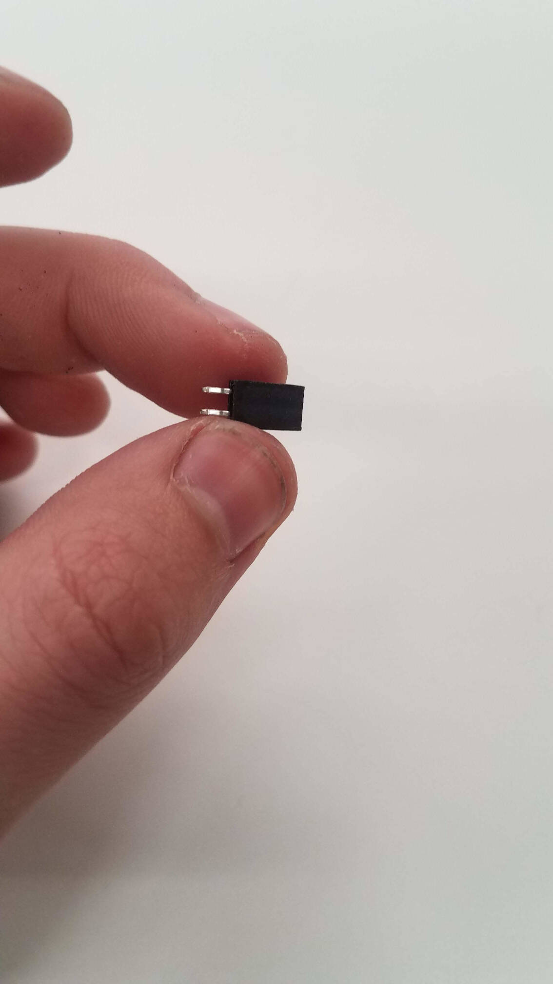
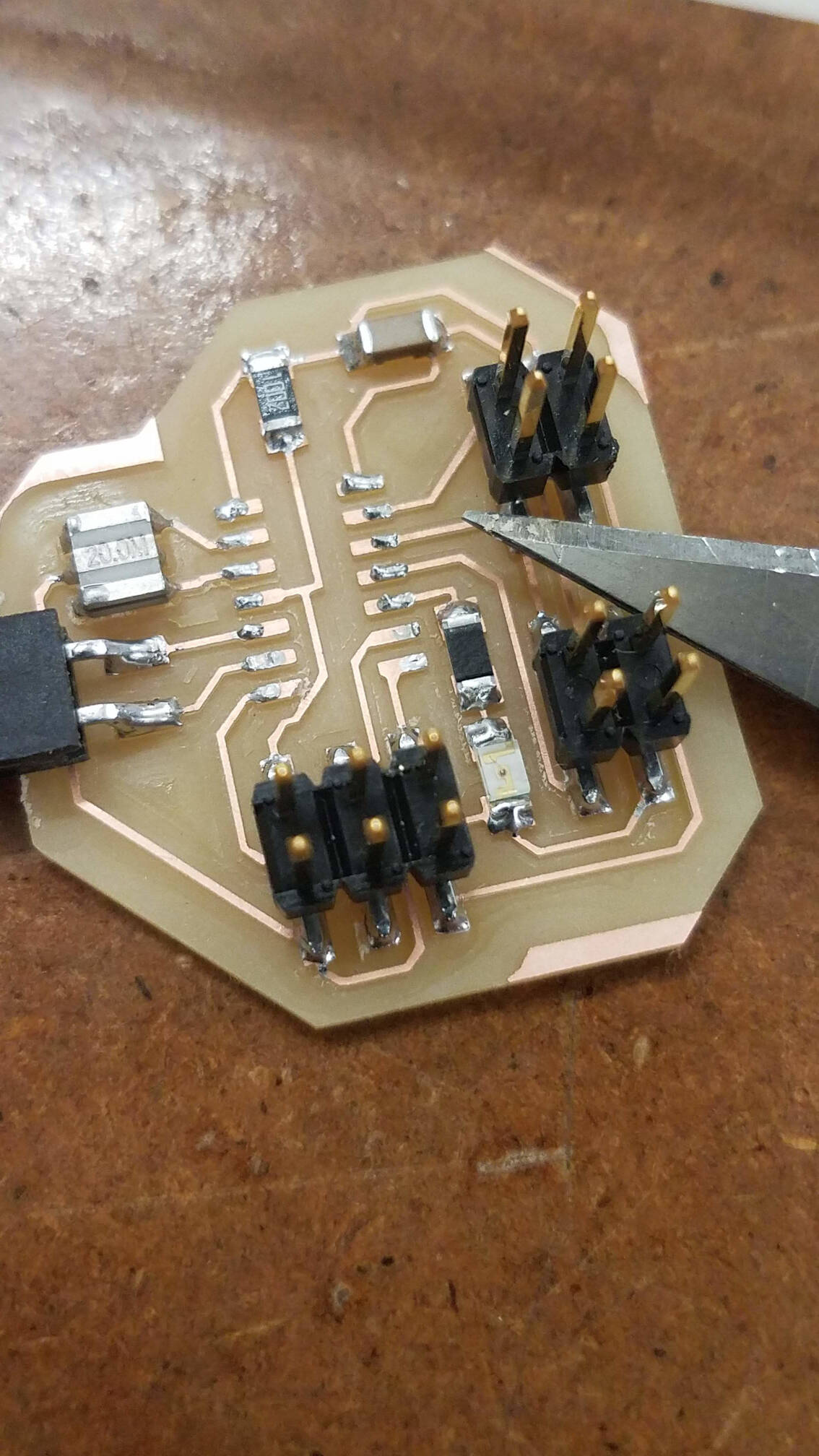
I had some fun with the components here. Along with my knock board, I wanted this board to have a 1x2 surface female connector, which we don't stock. I got creative with the 1x6 "FTDI" female jacks, and cut them with the diagonal cutters. I sanded them down, and made a KiCAD footprint for them by copying and modifying the original 1x6 FTDI. It felt slightly hacky, but also really fun, and a nice exploration of footprints and components.
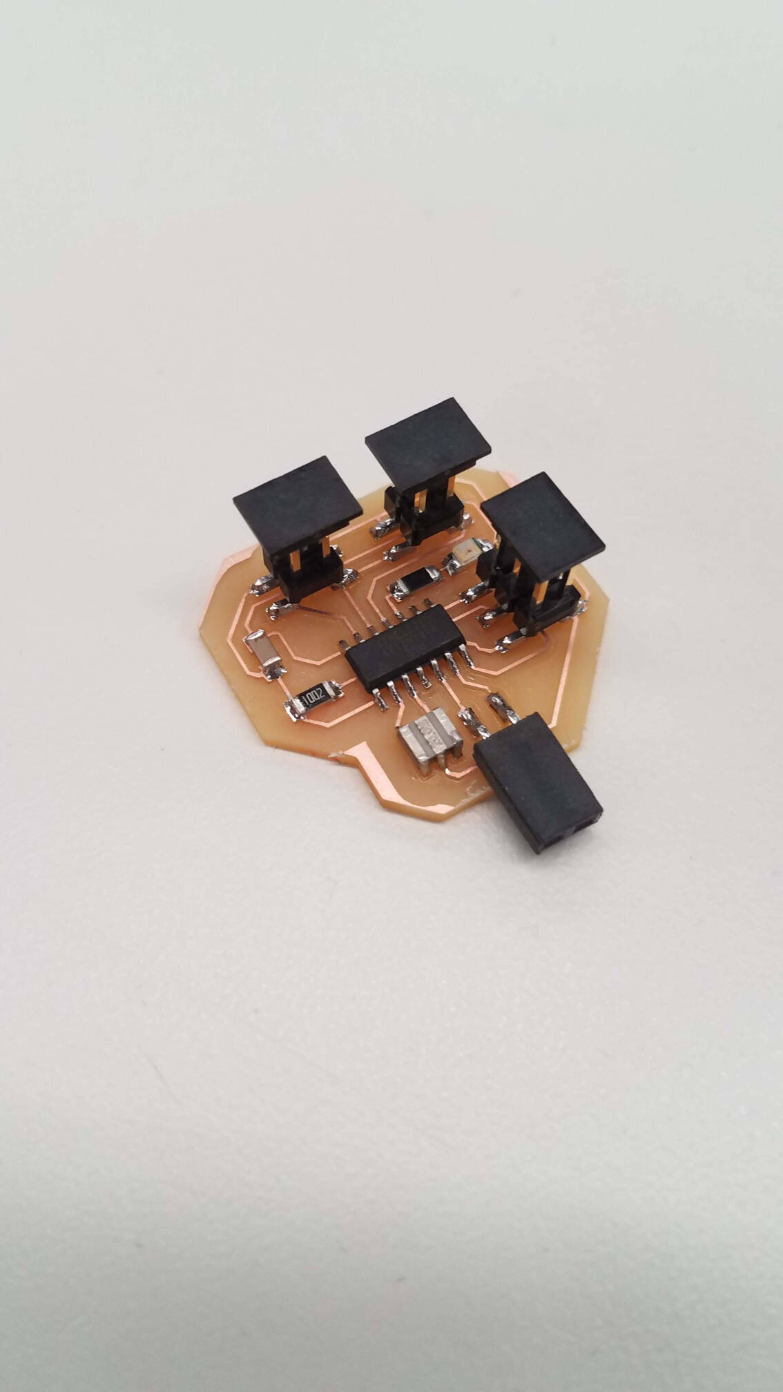
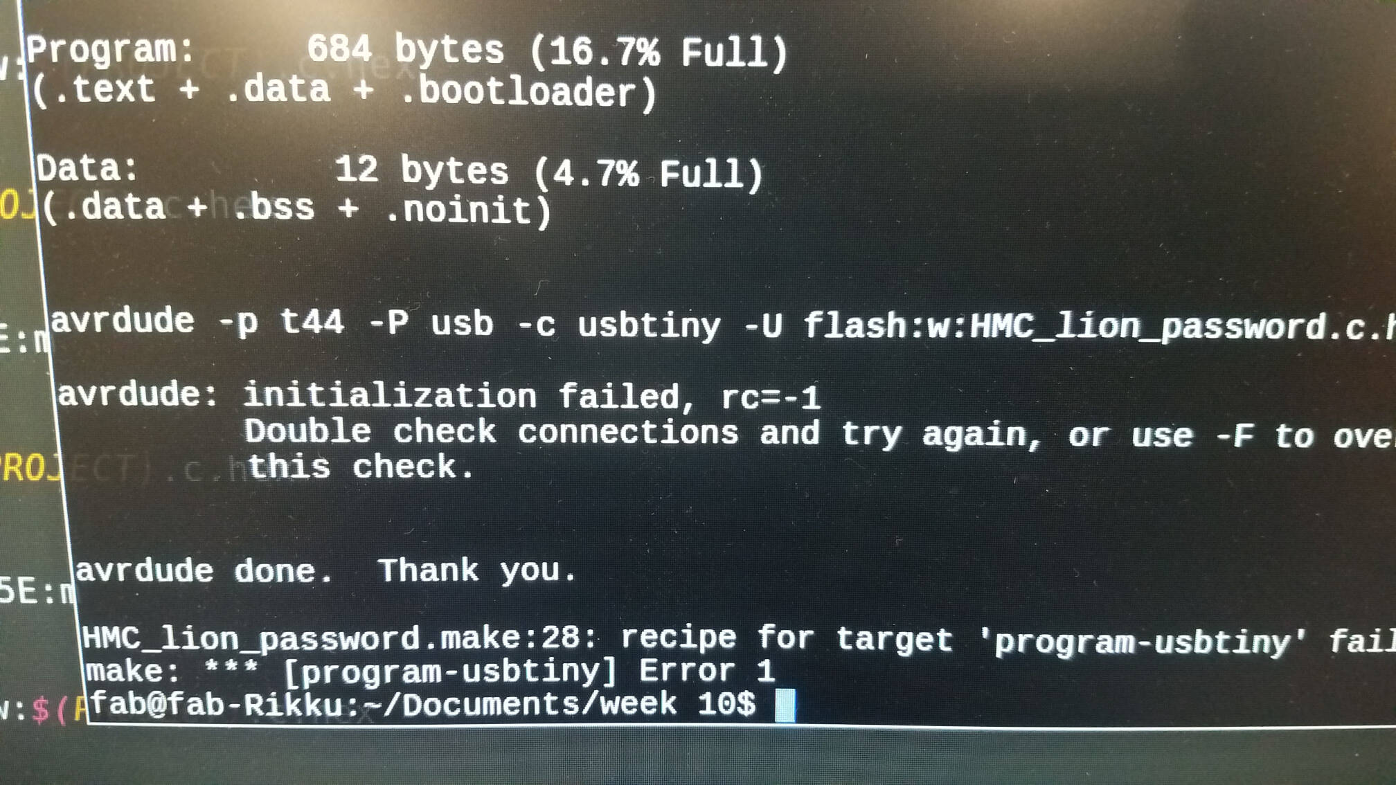
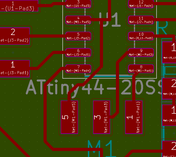
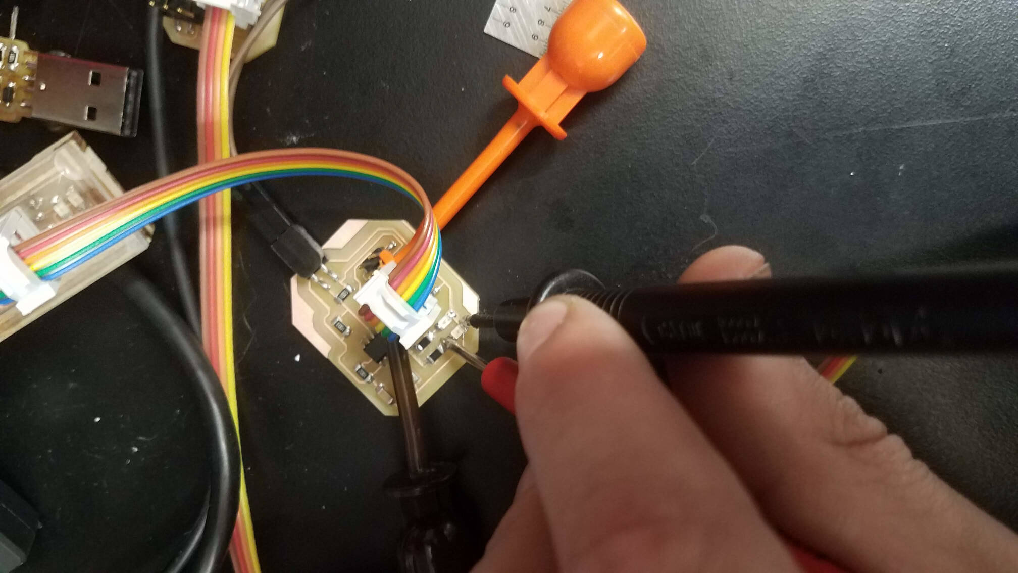
I soldered it up, plugged it in, annnnd... got an rc=-1 error. The programmer had its light on, was showing up on lsusb, so I figured it was an issue with the board. Turns out I was right -- the original version of the above PCB layout had one corner that cut too close to a pad, something I've been conscious about avoiding until now. I noticed this by probing with the multimeter, finding a connection I shouldn't have.
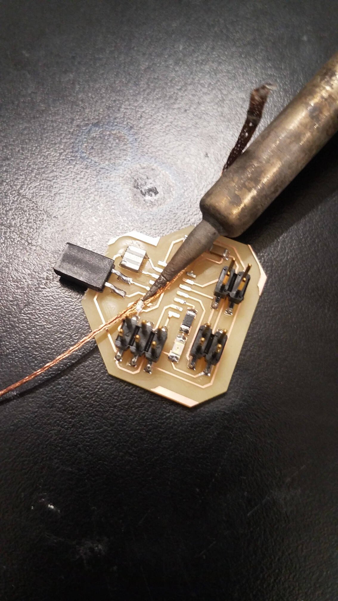
I fixed it up with a quick desolder and a knife, and the circuit programmed perfectly. Unfortunately, I couldn't get the network to (net) work. I initially tried setting up some framing, before sending the knocks over, but the framing failed, and then the code got stuck in the get_char loop.
Trying to fix that, I fiddled with some pins in the code, and got varying results. It got late, however, and one fiddle messed something up in the circuit. The LED's stopped turning on, even while the circuit programmed. I replaced the LED's, but they still wouldn't go on in the circuit. I checked the old ones, and they lit up, which I take to mean some short got created, possibly in the microcontroller. I'll replace the ATtinies and try this again soon.
Later:
I finally discovered that the output signal for the knock board, which would accurately go low across a scope, wasn't driving the pin of the password board low enough when connected (it was hitting about 2.5V instead). I found some other issues with the knock board (addressed at the end of the week 8 documentation), which didn't fix the problem, but might have messed up the microcontroller. I'll make some more changes to try and fix this up. (Below: knock board signal unconnected and connected, respectively).
Still later:
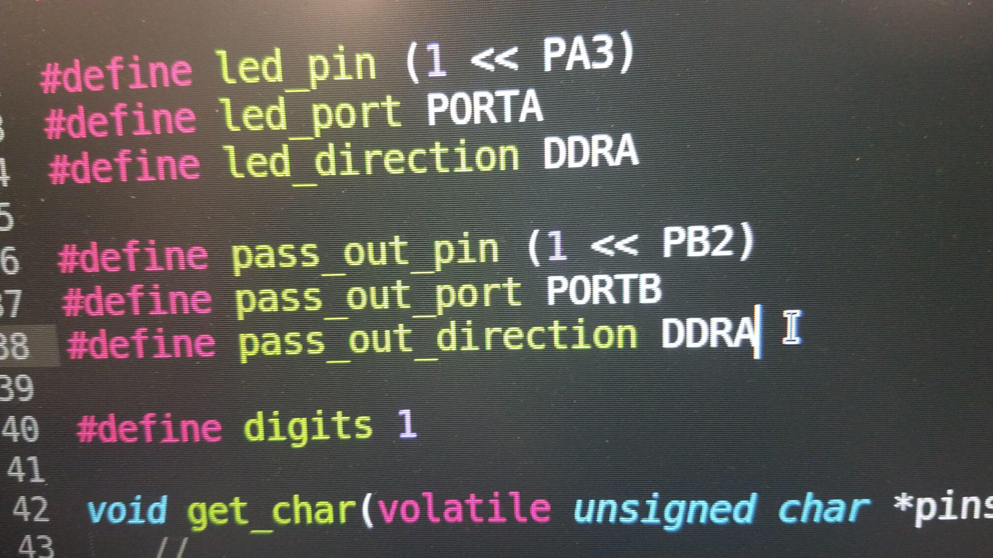
Aaand I did. After fixing the knock board, I was able to fiddle more safely with the code, and try some things up. After testing a couple situations, it looked like the pin was set as an output instead of an input. That didn't make sense though, because I never set that pin as an output... or so I thought. While I never set PA2 as an output in DDRA, I DID set PB2 as an output in the WRONG DIRECTION REGISTER -- I had the signal out direction, for a pin that I'll use to activate the next stage of the puzzle, as DDRA instead of DDRB. Because PA2 and PB2 are the same in code, this set PA2 as an output, causing my problem. I fixed this up and I FINALLY got it. Shown below is a video of entering 7 knocks with the password board accepting that as the correct password! I was even able to get it to work on multiple digits, which felt REALLY good.