Knock board
My purpose for this week is to set up the inputs. I had some ideas about a weight-based system, but for something to be a "key" for that, I'd have to measure absolute weight. I don't want to have zeroing be something that needs to be done regularly, so I switched to some other ideas. I settled on the idea of a password, with some fun ways to input it (this also helps the problem of displaying the final project without giving away how to open it).
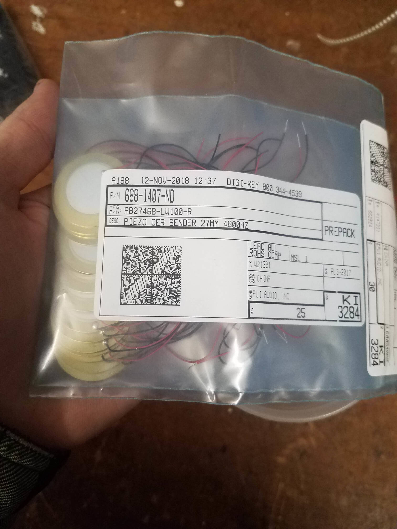
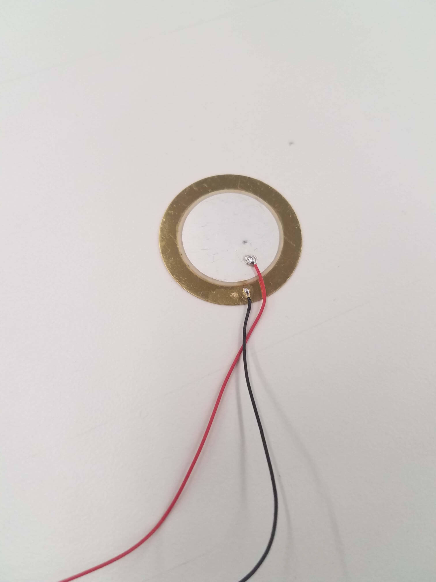
Instead, I want to make two things -- a board that counts knocks when a bit is on, and a load cell that will power that bit on when held. For the second, I ordered a load cell, because creating a strain gauge myself feels difficult. In my final documentation, I'll make sure to go into how those work, as I'd like to make sure I understand. That'll be something to work on outside of this week. For the knock, however, I used a piezo transducer, which we had a ton of.
I ended up pretty behind on this week, due to being pretty wrecked by a cold, and will be working on filling in the documentation of my work as I go along with week 10.
Later:
Working on the board on and off for two weeks, I ran into some difficulties. First off, I had issues with the oscilloscope. I didn't really know how to use it, and struggled for a bit with a flat signal with a small sine wave. As it turns out, this was due to a faulty ground connector, showing only the 60Hz AC ambient oscillations. Below is a picture of how that ungrounded signal looks (I also had it AC coupled, instead of DC).
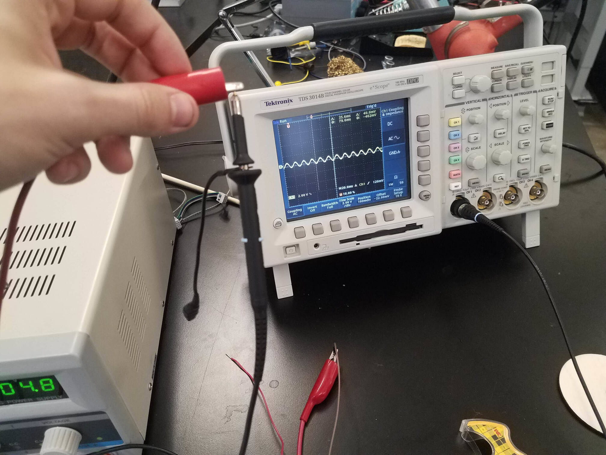
With that fixed, I set up a voltage divider across two 100K resistors, and put the piezo in parallel with the second. I measured the voltage drop across that parallel, and saw some sizeable spikes when I knocked on wood with the piezo against it. I set the trigger for 3.5V, which very consistently showed up on the oscilloscope, and is easy to check with ADC on a microcontroller.
Initially, I made a board with an FTDI header for the 6 connections I needed (power, ground, two piezo ends, and two network lines). On this board, I used the wrong resistors, and the voltage spike wasn't very strong. I did, however, use this board to test the first bit of my code. As some form of debouncing, my methodology was to separate the measurements into blocks, and just see if the piezo ever went high in that time. I set the block length, as well as the number of blocks necessary as delay between knocks, as constants in this test code. This version waits for one of the network lines (the "go" or "count" signal) to go low, turns the green LED on, and then blinks the red LED at the frequency between knocks, which is 12 block delays. This version doesn't use ADC, but the datasheet says ADC takes about 13us, which I used to ballpark the checking cycle.
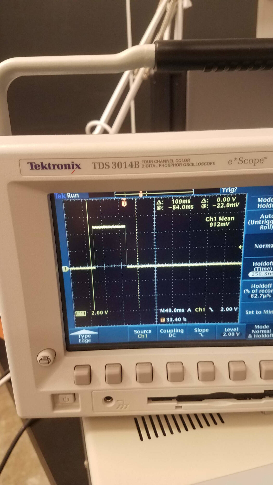
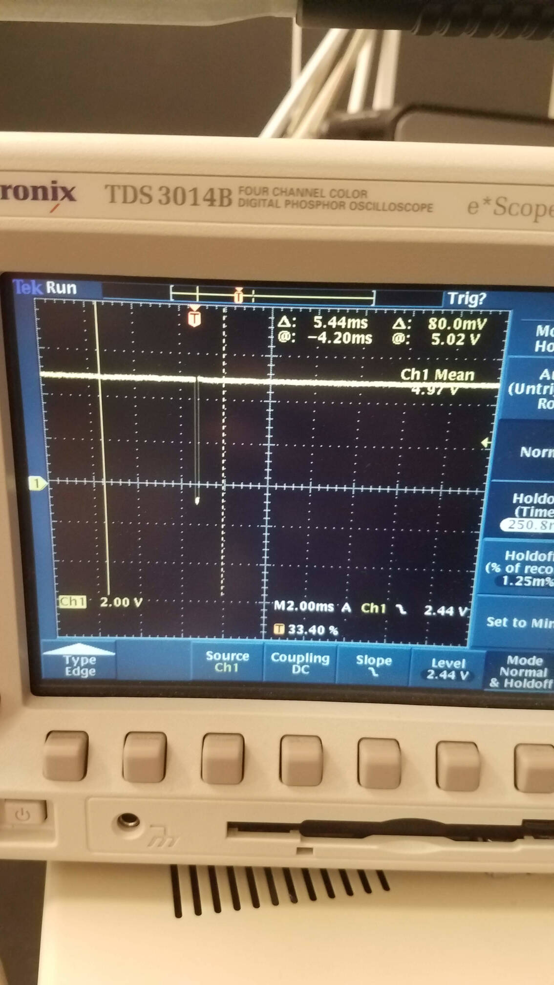
Finally, I set up a new board, and implemented this code. It worked almost perfectly -- knocks counted up to 9 while the go signal was on (knock count shown by a red LED flash, go signal shown by green LED on/off). However, I had a weird issue with a sort of short. A knock on the piezo was sending current back into the microcontroller, causing a faulty green LED flash if the actual go signal wasn't held. I tested the pins with an oscilloscope to see if the current was going straight to the LED, or triggering the go signal. Looking at the green LED pin (pictured first), the time matches a measurement block when the go signal is recieved. This made the latter more likely, and the measurement of the go signal showed that.
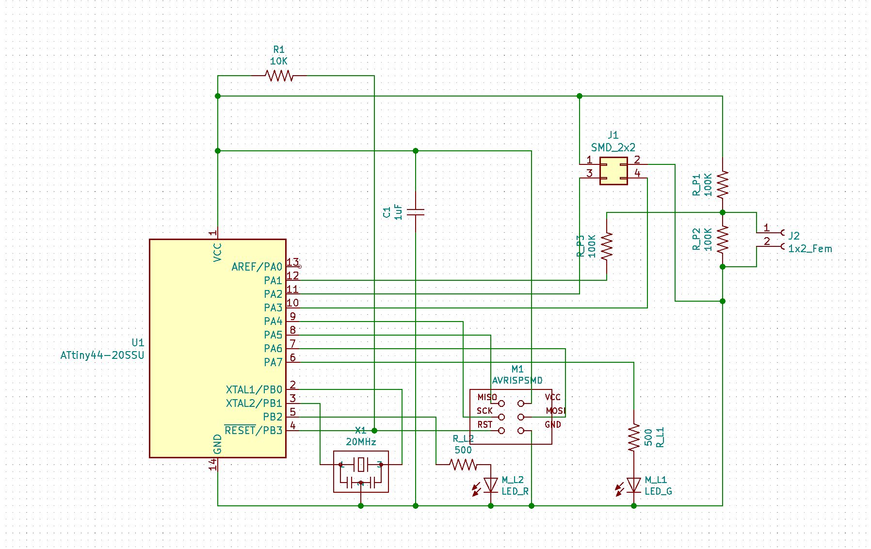
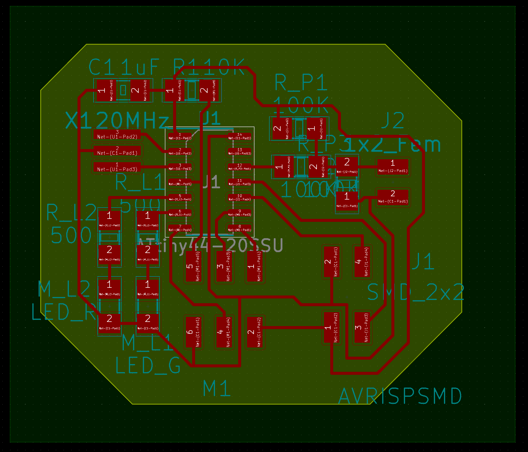
I fixed this with a large resistor, which still let me measure the voltage. The board was started with the consideration of networking in mind, but not fully implemented at this point. Check out how that went in week 10. The final schematic and board are below, as well as a video of it working!