Holdups
For this week, I wasn't exactly sure what to focus on. My final project isn't going to need an interface, and the boards that I'm making aren't too complicated outside of how they interact with input and output devices. However, I spent the past two weeks banging my head into getting my REALLY SIMPLE networking to work, so it might be nice to have a way to debug.
Specifically, a bunch of my boards function sort of like state machines, and it's hard to probe exactly what state they're in. Up to this point, I've mostly used LEDs on the board to do that, which have been doing a pretty solid job. However, it would be nice to have something that could see what the state is.
Before doing that, though, I had to get my boards even working right. I had just fixed an issue with a backwards signal going through my piezo transducer, which FINALLY helped me solve the issue at hand -- a coding mistake where I set the direction register of a B pin as DDRA. That was a GREAT reminder to double and triple check that, and a nice experience in diagnosing that problem. Check my week 10 documentation to see the final results of that!
At this point, however, it was pretty late in the week. In the past, I tested out coating a board with Smooth-On's 3D print finish coating, which worked great. I've been working hard to keep these boards from tarnishing, and I kinda liked the idea of sealing a working board. HOWEVER. This board had a different connector. My awesome amazing 1x2 female connector that I was so proud of making... was not sealed at the base.
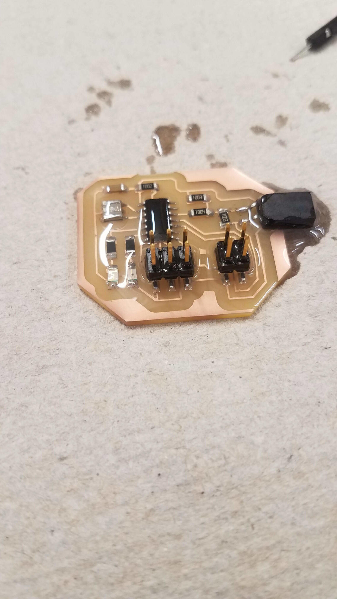
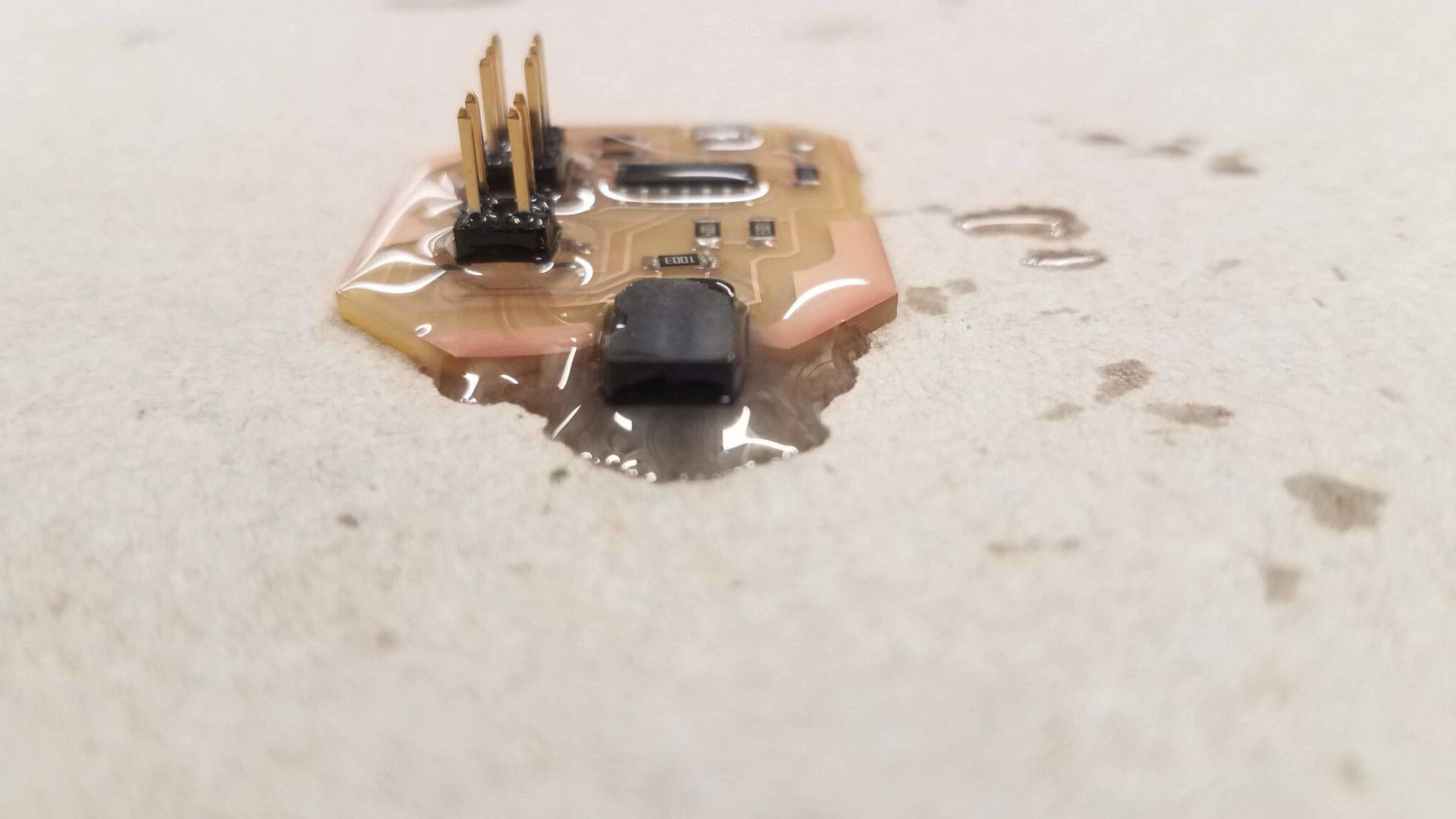
The coating, which was staying on the board through surface tension everywhere else, leaked into the connector. The holes filles up and spilled out. This trashed the board, and totally tanked my ability to work on the interface. I'll remake the board next week, and make a push to make some sort of interface before all of these assignments are due. Overall, however, finally solving my network issues was a big win!
Later: Serial hacks
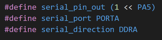
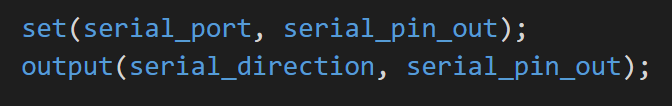
As part of my final project, I put together a load cell board. Check out the schematic, traces, and code over there. To get it to work, I accumulated 100 differential ADC measurements with the 1.1V internal reference on the tiny44. To get a sense of what that looked like, I wanted to set up an easy serial port on any board I had made. I decided to resuse PA5 from the programmer, and turn the ISP header into a hacky serial output. Essentially, inserting the following lines of code (to the head, and start of main loop, respectively) would allow any of my programs to output to serial through the already attached programming header.
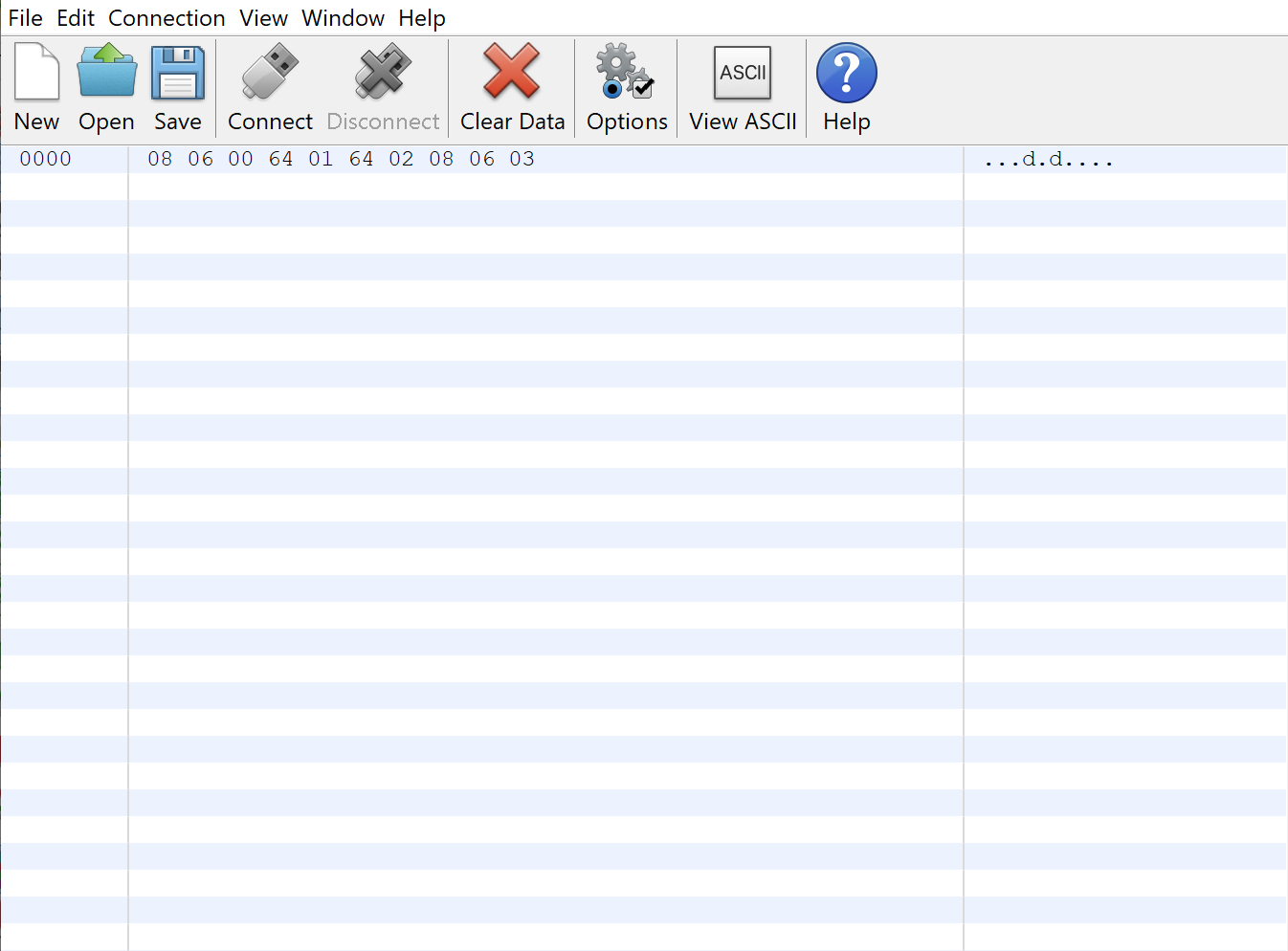
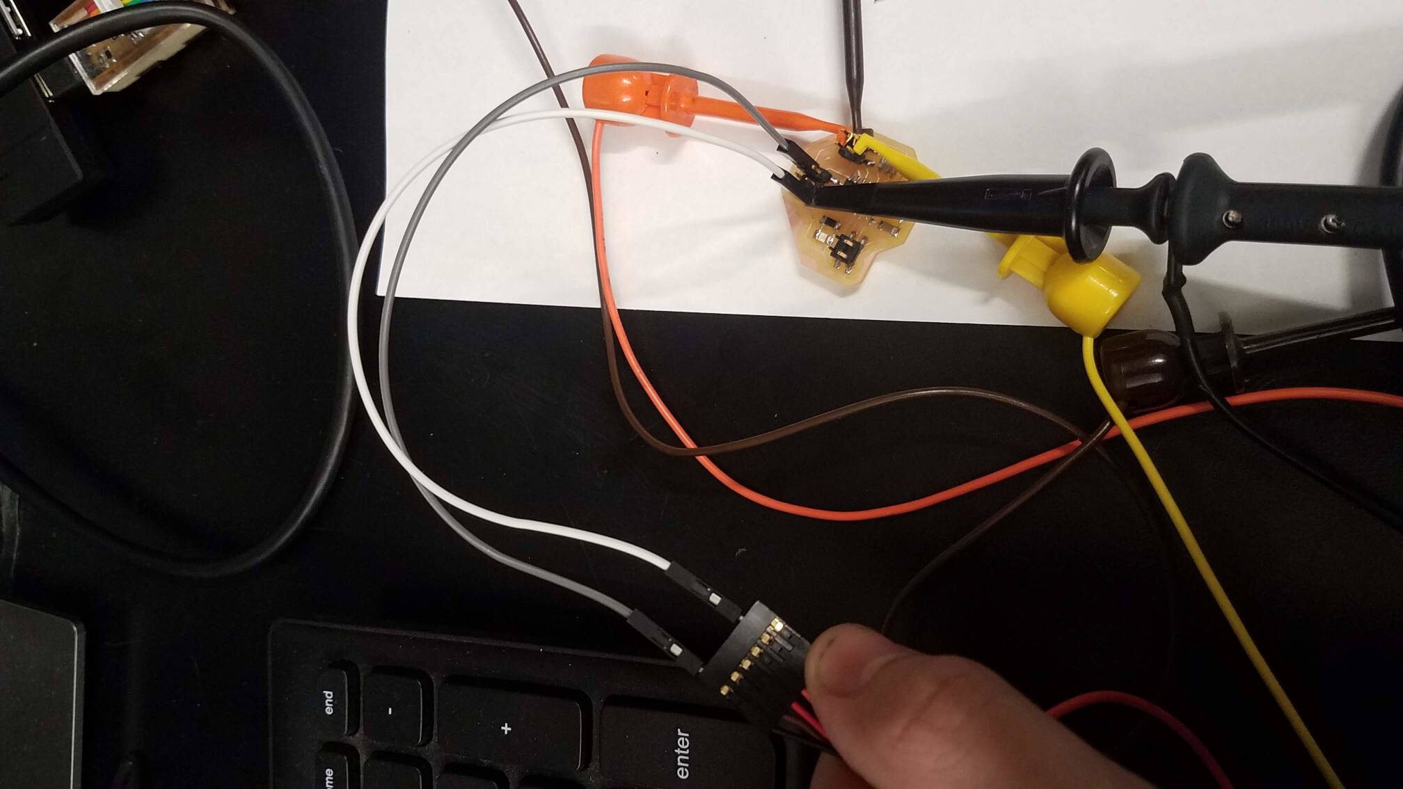
This worked amazingly. I connected an FTDI cable to the ISP header, only needing the ground pin and my serial out. I used CoolTerm to read bytes that I wrote using Neil's put_char code that I ported to my boards (and had already been using to bitbang knock count between boards).
I used this to find a reasonable threshold for my load cell, pushing on it with what I felt was the right amount of force and seeing what the output ended up being. I implemented the same code in my password board, and was able to track the current state of the digits. This is awesome if someone needs to debug my boards at any point in the future, and it's nice to know I can use this on ANY board I make with an ATtiny44.