Hello Reset
I was pretty behind due to a tough week last week, but this week was thankfully pretty manageable for me. My goal was to take the helloworld board from week 4 and program in a reset button for the string. I'm short on photo/video documentation, due to rushing a bit, but I felt confident with the steps I did take. This will be an area I need to explore for my final project, so I'm sure I'll get more time to do so.
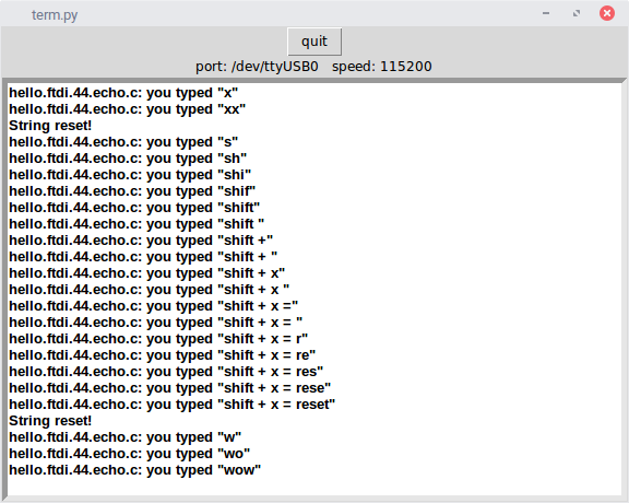
The first thing I did was to implement the string reset. This was pretty manageable to code, although I had trouble with the restrictions within the architecture. I couldn't declare variables inside for loops, which was manageable, but there were also restrictions that I found on needing to use static typing. I want to explore this further to understand the restrictions. However, I was able to set "X" as a reset character, which worked perfectly!
After that, I learned to deal with outputs and inputs. I first just set the LED as on, and later made it switch with every bit (in the future, when I go through a similar process, I'll save the code I've written for each of these steps. I didn't do that here, which was a documentation mistake). Understanding the ports, pins, and ddrs was a process, but I feel confident with my handle on it.
For input and output, the attiny44 has two sets of 8-bit registers, the second set of which doesn't use all of its bits (due to not having 8 pins). Each set has ports, pins, and ddr, and all bits of the same number correspond to the same physical pin. The pins are set by outside signal and power, and the ports are set internally. The ddr register determines how these are interpreted. If a bit in ddr is set to 1, the channel is an output, and the port sets the output value. I'm not sure if the pin has functionality in this mode. If a bit in ddr is set to 0, the channel is an input. In this mode, the pin is the read input, but the port can be set as a pull-up, defaulting the pin to high. You can test the input bit in pins (bitwise & and | were amazing for this).
For an LED, it was easy to turn it on. After setting the LED bit to 1 in DDRA, just setting the LED bit high in PORTA (the LED was on PA7) turned it on. For the button (on PB2), I needed to set the 3rd bit of PORTB high, and a low reading on that bit in PINB was a depressed button. For the button, I didn't spend time learning about interrupts or debouncing. I wanted the button to activate when held down for a period of time. This resulted in a struggle with the clock that I never fully finished.
The goal was to hold the button down for a set period of time to reset. When the button was held for long enough, the LED would light up, and then releasing the button would reset the string (and turn the LED off). At first, I tried a single integer increment to count how long the button was held down while the board was waiting for a character. This overflowed way too fast -- I'm not sure how big the int types are on the attiny44. After that, I tried stacking multiple loops of integers. This worked in raising my time, but was still immediate. Worse, I ran into something I think was a memory issue, where strings typed didn't display fully.
Finally, I used a 2ms delay between each incrementation, which let me just increment up to 1000 to make it wait two seconds. The result works just like I wanted it to, but I want to understand more about how the clock and timing systems work, as well as getting comfortable with interrupts and the architecture restrictions. I'll be exploring this more in the future, probably during week 8. In the meantime, this was a nice introduction!
My code can be found here, along with the makefile and the terminal.