SCROLL
finalProject 0000 0001 CAD 0010 cutting 0011 programmer 0100 3Dprinting 0101 elecDesign 0110 makeBig 0111 embedProg 1000 moldCast 1001 inputs 1010 outputs 1011 networks 1100 machine 1101 interface 1110 wildcard 1111 notes
0110
Embedded Programming
Group Assignment:
- compare the performance and development workflow for other architectures
Individual Assignment:
- Read a microcontroller data sheet
- Program your board to do something
Read a Data Sheet
Conjured out of the dusty, cobwebbed annals of my childhood:

This is the most daunting week by far. Learning to use machines is doable, as is soldering components on a board, directed by a diagram, but this... this seems impenetrable. One cannot "just read a data sheet" as was suggested. I got two lines in before I had to go on a half hour Googling sojourn. The line that stumped me-- "Port B is a 4-bit bi-directional I/O port with internal pull-up resistors (selected for each bit)."
Port B
- Made up of the 4 pins labelled PB0 to PB3
4-bit
- 4 legs, each can be on ( 1 ) or off ( 2 )
Bi-directional I/O port
- Bits can be received and transmitted from these pins
Internal pull-up resistors
- pull-up resistor
- When a pin of a micro controller (uC) is neither connected to Vcc or to GND it is said to be floating - this is bad, pull up resistors prohibit floating
To be clear, this was one of the more digestible sentences of the document
Programming my board to do something
First I'm going to program my board with existing code from Julia Ebert's page. Then I will play around with her code to see what happens with my button and LED.
I am using Sublime text to edit my code.
Here are the code blocks that define the behavior of the board:
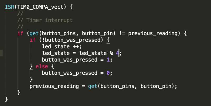
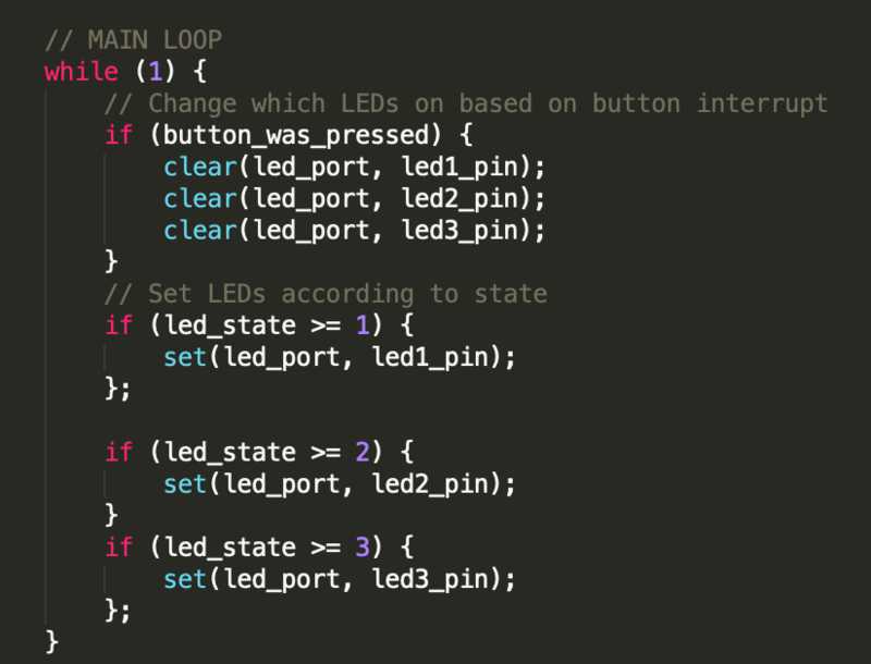
From what I can tell, the use of the modulo operator% in the top function will keep the led_state value between 0 and 3. The % operator returns the remainder of dividing the left argument by the right. Therefore, when modding a multiple of four by four, 0 will be returned.
The loop ensures that when led_state = 0 that no LED is on. Julia has three LEDs, I have only one. I expect my LED will stay on for four clicks then off.
I am connecting my previously fabricated programmer and my hello world board to each other and my computer as usual:
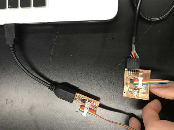
Using this as reference, I loaded Julia's program onto my board.
These were the commands I ran from within the directory I have Julia's .c and .make file saved:
make -f hello.ftdi.44.button-interrupt.c.make(this will compile my code creating a hex file)sudo make -f hello.ftdi.44.button-interrupt.c.make program-usbtiny-fuses(still not sure what thefusescommand does)sudo make -f hello.ftdi.44.button-interrupt.c.make program-usbtiny(loads program onto board)
(I ended up making a bash alias in ~/.bash_profile for these three commands so that all I have to type to reprogram my board is programJulias )
Here is a good reference for what these commands do

Seems to have loaded successfully.
Change it
I want to start with something simple to make sure I understand Julia's code.
I think if I change the line where led_state is modded by 4 to modded by 2 then I will be able to turn the LED on with one click and off with the next click.
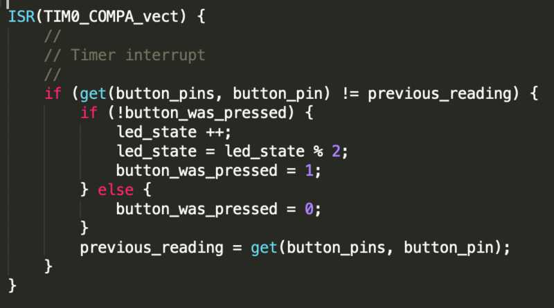
I saved the file and am now running programJulia in the directory with the file.
Success!
I am now going to go through all of the relatively arcane lines in Julia's code to see if I can understand more of it.
Exploration
With the minimum criteria of the assignment fulfilled I would like to go and do some extra digging into what exactly I did above and how it works
What is "serial" data transfer?
https://learn.sparkfun.com/tutorials/serial-communication
Parallel = 8 bits (1 byte) transferred at a time. 9 wires required: 8 for target data and one for a clock
Serial = 1 bit at a time
- Synchronous serial = with a clock
- Asynchronous serial = without a clock (more common)
With asynchronous serial data transfer some rules must be followed to ensure proper transfer of data.
Data bits
Synchronization bits
- two or three special bits transferred with each chunk of data. They are the start bit and the stop bit(s)
- mark the beginning and end of a packet
Parity bits
- Parity is optional, and not very widely used
Baud rate (similar to bit rate, except that the basic datum unit may be more than one bit)
- how fast data is sent
- determines how long the transmitter holds a serial line high/low or at what period the receiving device samples its line
- usually won't see speeds exceeding 115200
It is critical that both devices on a serial bus (a connection between devices) are operating under the same protocol
9600 8N1 - 9600 baud, 8 data bits, no parity, and 1 stop bit - is one of the more commonly used serial protocols
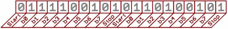
Since we're transferring at 9600 bps, the time spent holding each of those bits high or low is 1/(9600 bps) or 104 µs per bit.
For every byte of data transmitted, there are actually 10 bits being sent: a start bit, 8 data bits, and a stop bit. So, at 9600 bps, we're actually sending 9600 bits per second or 960 (9600/10) bytes per second.
Wiring and Hardware
A serial bus consists of just two wires - one for sending data and another for receiving. As such, serial devices should have two serial pins: the receiver, RX, and the transmitter, TX
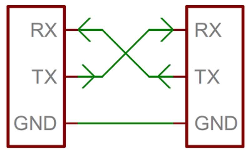
It's important to note that those RX and TX labels are with respect to the device itself.
The RX from one device should go to the TX of the other, and vice-versa
Full-duplex = both devices can send and receive simultaneously
Half-duplex = serial devices must take turns sending and receiving
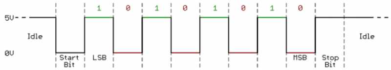
When microcontrollers and other low-level ICs communicate serially they usually do so at a TTL (transistor-transistor logic) level. TTL serial signals exist between a microcontroller's voltage supply range - usually 0V to 3.3V or 5V. A signal at the VCC level (3.3V, 5V, etc.) indicates either an idle line, a bit of value 1, or a stop bit. A 0V (GND) signal represents either a start bit or a data bit of value 0.
So that explains the RX and TX pins
What is a driver?
https://docs.microsoft.com/en-us/windows-hardware/drivers/gettingstarted/what-is-a-driver-
It is a software component that "knows" how to communicate with a device. A driver is used by an operating system to retrieve data from a device and "translate" it into a form comprehensible to the operating system of the computer being used.
What is all the gobbledygook in the .c program!?
I am going to go through it piece by piece...
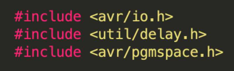
This allows access to functions we need that are held in the listed libraries (in yellow)
This next block is quite a beast:
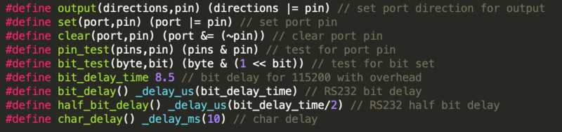
The #define means we are giving our own names to the operation defined by the code in the last pari of parentheses on each line, but what the hell is that operation...
To Google!
Research done, time for a lesson on:
Bitwise Operations in C
https://en.wikipedia.org/wiki/Bitwise_operations_in_C
| Symbol | Operator |
|---|---|
& | bitwise AND |
| | bitwise inclusive OR |
^ | bitwise XOR (exclusive OR) |
<< | left shift |
>> | right shift |
~ | bitwise NOT (one's complement) (unary) |
Bitwise AND ( & )
| bit a | bit b | a & b (a AND b) |
|---|---|---|
| 0 | 0 | 0 |
| 0 | 1 | 0 |
| 1 | 0 | 0 |
| 1 | 1 | 1 |
xxxxxxxxxx11001000& 10111000--------= 10001000
Bitwise OR ( | )
| bit a | bit b | a | b (a OR b) |
|---|---|---|
| 0 | 0 | 0 |
| 0 | 1 | 1 |
| 1 | 0 | 1 |
| 1 | 1 | 1 |
xxxxxxxxxx11001000| 10111000--------= 11111000
Bitwise XOR ( ^ )
| bit a | bit b | a ^ b (a XOR b) |
|---|---|---|
| 0 | 0 | 0 |
| 0 | 1 | 1 |
| 1 | 0 | 1 |
| 1 | 1 | 0 |
xxxxxxxxxx11001000^ 10111000--------= 01110000
Bitwise NOT ( ~ )
| bit a | ~a (complement of a) |
|---|---|
| 0 | 1 |
| 1 | 0 |
xxxxxxxxxx~ 11001000--------= 00110111
Right Shift ( >> )
If the variable ch contains the bit pattern 11100101, then ch >> 1 will produce the result 01110010, and ch >> 2 will produce 00111001
This is the equivalent of dividing ch by
a >> n =
New places are filled with s
Left Shift ( << )
If the variable ch contains the bit pattern 11100101, then ch << 1 will produce the result 11001010
This is the equivalent of multiplying ch by
a << n =
New places are filled with s
Ok, but what about the =| and =& ???
Bitwise Assignment Operators in C
| Symbol | Operator |
|---|---|
&= | bitwise AND assignment |
|= | bitwise inclusive OR assignment |
^= | bitwise exclusive OR assignment |
<<= | left shift assignment |
>>= | right shift assignment |
The trailing = just means that the result of the operation will be stored in the left operand, ie after a |= b the variable a will hold the resultant value of the bitwise operation.
Ok, but...
WHY??? What is all this pin-setting business???
This I cannot answer...
It will take quite a bit more reading to understand everything in the program I used.
I've Got It!!!
At least some of it...
The basics:
A register is a place in memory with 8 slots for either a 0 or 1 to go in.
A micro-controller is capable of many different operations, but to specify what operation you want done you have to find the register that controls that functionality (via the data sheet) and set those 8 zeros and ones to a specific pattern (documented in the datasheet).
To set those 8 zeros and ones you use the bitwise operations outlined above.
Example:
A register starts out equalling zero:
00000000
Lets call this register ABC
Say you want to make your micro-controller use pin X to perform operation Y
The data sheet will tell you that in order to do this you must set register ABC to 01001000
(It doesn't actually say it with this notation, but I'll come back to that)
So how do you do that?
Well you can use |= to do that, like so:
xxxxxxxxxxABC= 00000000|= 01001000------------ABC= 01001000
Now ABC is set to the necessary pattern.
You can also use the other bitwise operations like &, >>, << to configure your registers.
In the data sheet the binary will not be presented, instead a lettered label for the binary will be shown.
FIN
(kinda)