SCROLL
finalProject 0000 0001 CAD 0010 cutting 0011 programmer 0100 3Dprinting 0101 elecDesign 0110 makeBig 0111 embedProg 1000 moldCast 1001 inputs 1010 outputs 1011 networks 1100 machine 1101 interface 1110 wildcard 1111 notes1100
Mechanical Machine Design
Assignment:
- design a machine that includes mechanism+actuation+automation
- build the mechanical parts and operate it manually
- document the group project and your individual contribution
Tasks:
ideate and general machine design
linear axis build
rotary axis build
frame construction
end effector
electronics assemble
programming
NB: The main group tracking page for this week's assignment is here
Idea
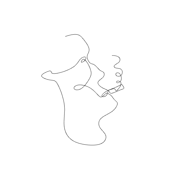
A painting machine that can replicate a digital line drawing with paint on canvas
Individual Contribution
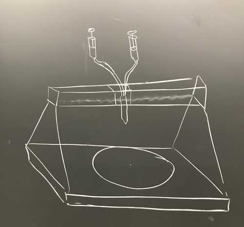
I helped with the initial mechanism brainstorming. The below sketch is our general idea for the painting machine.
Fabrication & Assembly
Laser cutting
3D printing
Assembly
Taking Jake's linear axis CAD files and hardware we constructed his linear axis design.
The yellow connectors were 3D printed on the Prusa 3D printer, as were the pieces for the blue sliding carriage.
The rubber belt was pre-made.
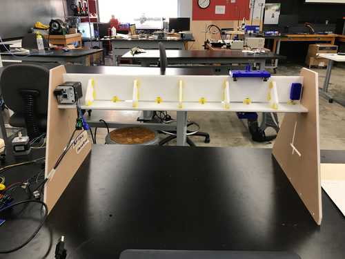
The lower platform in its original position as made by Lincoln and Phil. Sometime later Joon and I realized that this position assumed that the end effector would be located directly under the linear axis, when in fact the end effector (taped to the carriage) would be offset quite a bit from the linear axis.
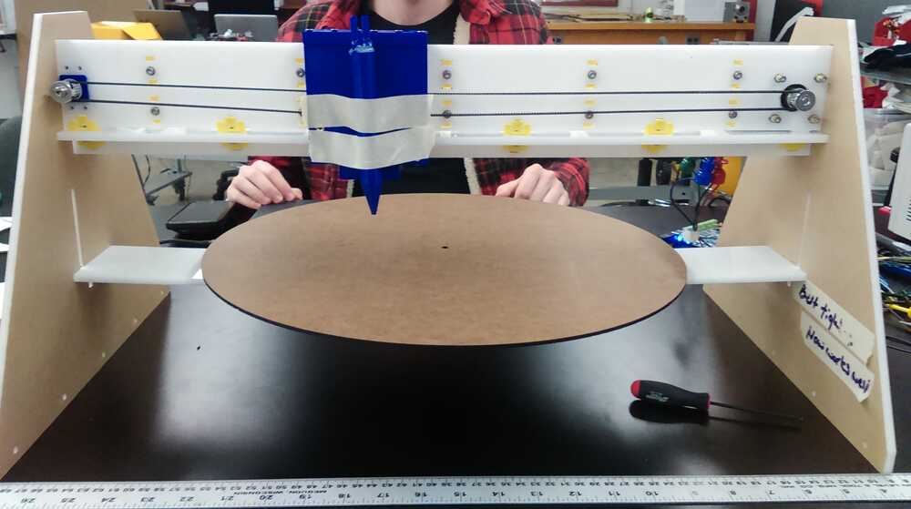
Joon and I then removed the lower platform and created supports to hold it where the end effector could be placed directly over the center line of the round platform.
With everything assembled it was time to get to work on the algorithm and eventual software that would make the machine do what we wanted
Programming
On the lab chalk board we started brainstorming algorithm ideas. The problem was synchronizing rotational movement of the lower axis with linear movement of the upper axis.
First step, rather than thinking about a line, think about a few points and figure out a way to get the end effector over those points.
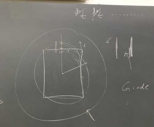
The linear axis need only travel between the center of the lower circle and its edge. That's a straight line. So we needed to find a way to mark where a point on the circle will eventually intersect with the radial line our linear axis is capable of moving over.
I started using hand drawings to simulate the rotation of the canvas, and hence the movement arc of a few points as they traveled to the radial line where the linear axis can move along. I assumed a constant rotational velocity of the canvas and plotted the four corners of a square and a few points along the sides. Incrementally numbering the location at which each point hit our line as the canvas hypothetically turned. That visualization was very helpful.
Next we needed to write it out mathematically - enter: polar coordinates.
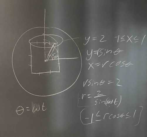
Joon was able to write (draw?) the program in grasshopper. This was great as grasshopper and Rhino (where we were making digital drawings for our machine) go hand in hand.
G Code
The tiny G takes in G code and turns that into motor output. Next I need to learn how to write G code.
A simple line of G code is made up of 4 elements. It looks like so:
xxxxxxxxxxg0 f1000 z100
G0
This selects the type of movement. G0 is for non-extrusion movements (what we are doing). G1 is for extrusion movements.
F100
This is the speed. F50 would be slower and F200 would be twice as fast.
Z100
Z is the motor selection. Z is configured to be our linear axis. 100 is the distance in mm. A positive value moves the motor clockwise and a negative value counterclockwise.
The above line should use non-extrusion movement to move the linear axis 100mm to the right at a speed of 100.
Here is part of a single axis test file created by our grasshopper program output
xxxxxxxxxxg0 f1000 Z-1.985749g0 f1000 Z-6.006049g0 f1000 Z-10.175632g0 f1000 Z-14.604177g0 f1000 Z-19.417927g0 f1000 Z-24.768936g0 f1000 Z-30.847847g0 f1000 Z-37.902039g0 f1000 Z-46.262759g0 f1000 Z-56.386916g0 f1000 Z-68.924082g0 f1000 Z2.685145g0 f1000 Z64.212032
With G-code it is possible to set the location and distance measuring to be relative or absolute.
This can be done by starting of with either
xxxxxxxxxxg91
Or
xxxxxxxxxxg90
The former is for incremental positioning and the latter for absolute positioning.
It is also possible to move to motors simultaneously by combining their commands on one line like so:
xxxxxxxxxxg0 f1000 y0.333333 Z110.0
The y motor would move 0.333333 and the linear 110.0
Here is a sample of our dual motor control g code:
xxxxxxxxxxg91g0 f1000 y0.333333 Z110.0g0 f1000 y0.333333 Z-12.425474g0 f1000 y0.333333 Z-5.97869g0 f1000 y0.333333 Z-1.922386g0 f1000 y0.333333 Z1.732948g0 f1000 y0.333333 Z5.341459g0 f1000 y0.333333 Z8.216984g0 f1000 y0.333333 Z4.910861g0 f1000 y0.333333 Z-7.791957g0 f1000 y0.333333 Z-7.942431g0 f1000 y0.333333 Z-3.829868g0 f1000 y0.333333 Z0.61758g0 f1000 y0.333333 Z4.942746g0 f1000 y0.333333 Z8.692919g0 f1000 y0.333333 Z5.167297g0 f1000 y0.333333 Z-8.23509g0 f1000 y0.333333 Z-7.703267g0 f1000 y0.333333 Z-3.571392
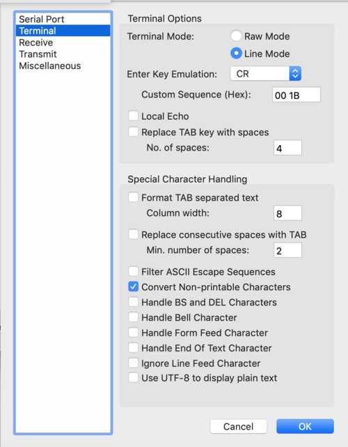
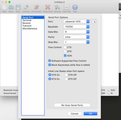
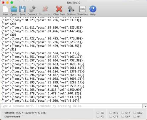
I am using CoolTerm to communicate with the tiny g over serial:
With our program running well, it is now time to test it out with some images. The videos at the bottom of our group machine page show the evolution of our control over our painting.
Our end goal (and result) was a computer controlled painting of this doodle: