SCROLL
finalProject 0000 0001 CAD 0010 cutting 0011 programmer 0100 3Dprinting 0101 elecDesign 0110 makeBig 0111 embedProg 1000 moldCast 1001 inputs 1010 outputs 1011 networks 1100 machine 1101 interface 1110 wildcard 1111 notes1010
Outputs
Individual assignment:
- Add an output device to a micro-controller board you've designed and program it to do something.
Group Assignment:
- Measure the power consumption of an output device
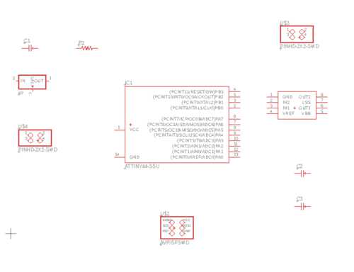
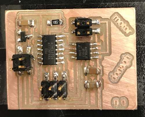
Board design
For my final project I need to program a board that will turn a motor to a specified position. I will use this week to become familiar with controlling motors.
It seems prudent to base my first design off of Neil's hello.H-bridge.44.DC circuit for a DC motor.
Let's get drawing in Eagle.
Parts (from eagleFab library):
ATTINY44-SSU
A4953-H-BRIDGE-MOTOR-DRIVER
AVRISPSMD
PINHD-2X2-SMD (x2)
REGULATORSOT23 (5V 100mA)
CAP-UNPOLARIZEDFAB (x3)
RES-US1206FAB
Now to draw the connections. I mostly prefer to draw short nets and label them rather than physically connect everything. I think it makes it easier to understand how each part should be integrated into the circuit.
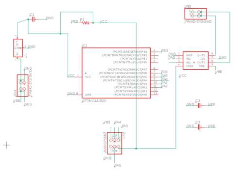
Switching to board now to design layout.
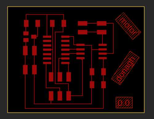
Export PNGs
- Hide all layers except traces
- File > export > image
- Set save location
- Dpi = 1000
- Check monochrome box
- ok
- Hide all layers except dimensions
- File > export > image
- Set save location
- Check monochrome box
- Dpi = 1000
- Ok
Milling
I used the same milling process as in past weeks to mill the traces and outline of my board.
Everything looked like it came out well until I noticed that all of the pads for the left side of the microcontroller were connect by a trace that was supposed to me disconnected from them. Clearly I had them too close together in my drawing and the milling machine knew the 1/64th bit was unable to make a cut that thin.
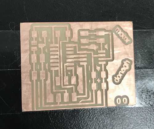
I attempted to perform surgery on my board with a scalpel, but ended up ruining more than I fixed.
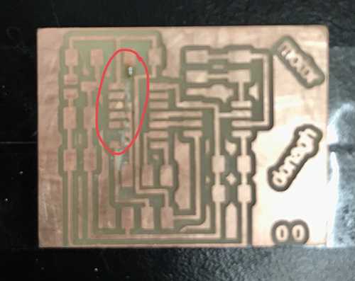
I edited my board drawing to fix this problem and will now re-mill.
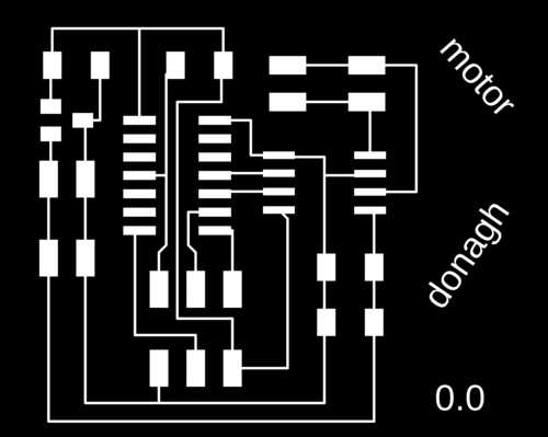
New traces and same outline:

Second iteration:
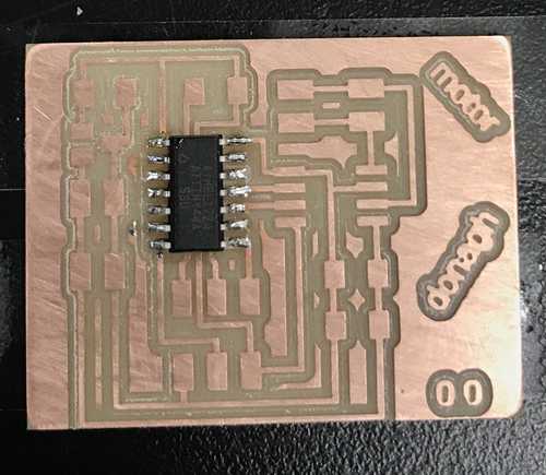
I was about to solder on the motor driver when I noticed it had a chrome colored pad on its underside. I then remembered that in Neil's board drawing he had left a fat chunk of copper underneath where the motor driver should go. Here is his design: http://academy.cba.mit.edu/classes/output_devices/H-bridge/hello.H-bridge.44.png
I am hoping that the trace I do have below the driver will be enough surface area to fulfill whatever function Neil's copper chunk is supposed to. I can hear Neil in my head saying, "when I do something there is a very good chance it's for a reason."
Programming
Downloading Neil's C and Makefile
Running the following from the directory containing the files.
make -f hello.H-bridge.44.DC.make
No need to run:sudo make -f hello.H-bridge.44.DC.make program-usbtiny-fuses
sudo make -f hello.H-bridge.44.DC.make program-usbtiny
Successfully programmed
Debugging
I cannot for the life of me get this board to work.
The motor definitely works. I connected it straight to the power supply and it spun.
There is definitely power going through the board. When I connect my programmer to the board, the LED on the programmer turns on. Similarly, when I connect the motor to any ground trace and any other VCC trace, the motor spins.
Using a multimeter I measured the voltage across many points on the board. All are as they should be except for the out2 pin on the H-bridge.
Back to the beginning
... Just had a hugely frustrating realization... I went back through my terminal output to confirm that the board had successfully programmed... it had not.
More frustrating now is that I keep getting the rc = -1 error.
When I list the devices connected to my Mac usbtinySPI shows up.
This past student's documentation on similar issues was very thorough.
After two hours (if I'm honest, three) fiddling around with this, I'm going to edit my drawing again and mill and solder a new board. Woo.hoo...
Drawing Iteration 3
Changes:
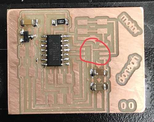
- Thickening some traces that, if I use a more demanding motor, will have to carry much more current than the "brain" of the board.
- Adding in the copper pad underneath the H-bridge's heat sink pad
Remilled
Resoldered
Programming attempt #2257930854
I set up the connections and BANG programs first time. At this point I'm thinking well lets just try the old board one more time now that I am sure the current cable connections are good. BANG "broken board" programs. This is something that would usually bring joy, except in this instance it brings the realization of around 5 hours of my day being used up on correcting something that was never broken.
Take aways:
- Board to be programmed needs power
- Programmer light should be on and BRIGHT, not just on
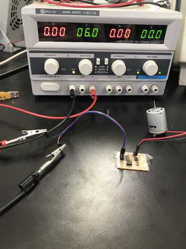
Motor Test
Looks good! Difficult to see the turning pattern with the cam on the motor as it continues to swing when the shaft stops abruptly. I also tested on other motors lying around the lab. They all exhibit the behavior outlined in the C program.
FIN