SCROLL
finalProject 0000 0001 CAD 0010 cutting 0011 programmer 0100 3Dprinting 0101 elecDesign 0110 makeBig 0111 embedProg 1000 moldCast 1001 inputs 1010 outputs 1011 networks 1100 machine 1101 interface 1110 wildcard 1111 notes1011
Networks
Individual Assignment:
- design, build, and connect wired or wireless node(s) with network or bus addresses
Group Assignment:
- Send a message between two projects
Individual Assignment
As my final project involves the use of cameras and face detection, I was pretty excited to see the face detection option in the demo video for the ESP32 module (timestamp: 1:39).
This week I hope to get the system up and running and sending a live video stream to my laptop.
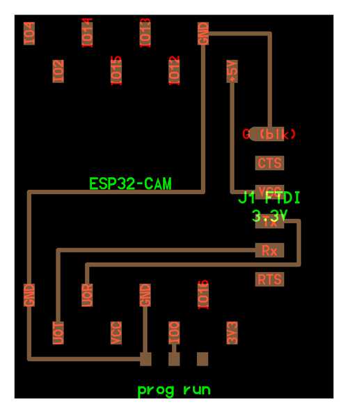
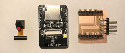
The traces to be milled are very simple as almost all necessary parts are on the ESP32-CAM module itself.
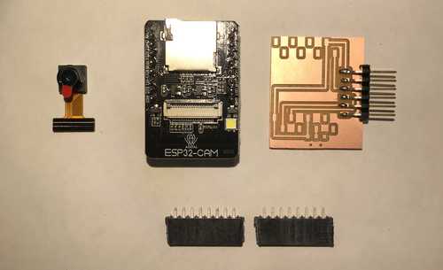
Components:
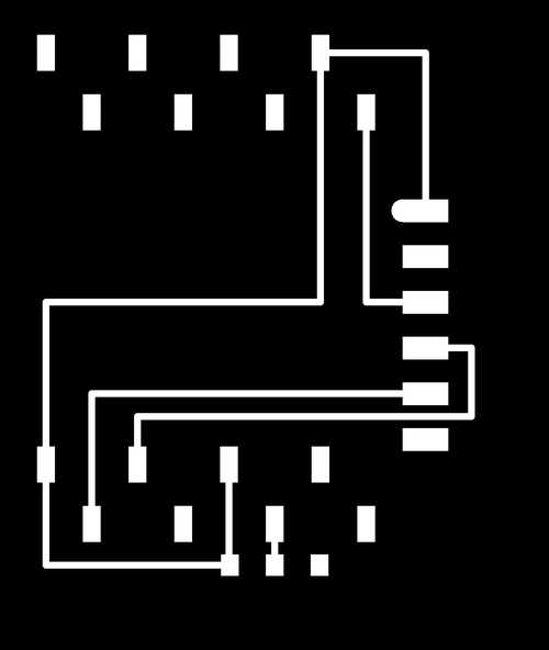
Traces:
Holes:

Outline:

I milled and prepared PCB as in past weeks.
Soldering
Went smoothly:
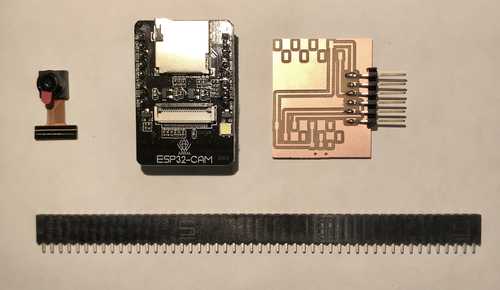
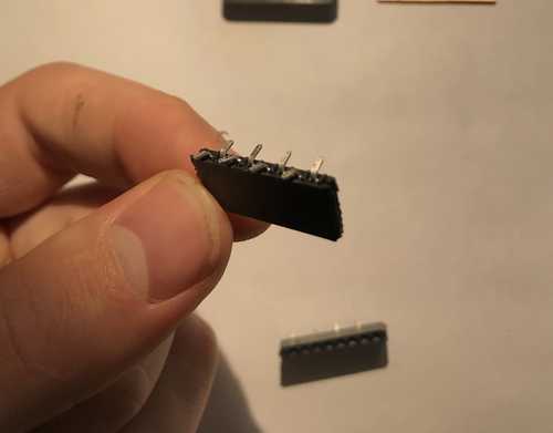
Snipped the socket series so that I had two 6 socket pieces
Using pliers I bent the pins to alternate sides so that they would lay on the copper pads of my board.
Soldering:
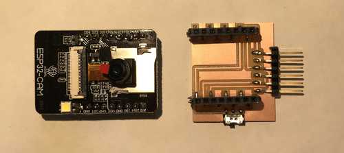
Finished
Setting up Environment
I am going to do my programming in the Arduino IDE for the first time.
After downloading and starting up the program the first thing to be done is add the ESP32 to the IDE's "additional boards"
Arduio > preferences > Settings > Additional Boards Manager URLs
Paste into the field: https://dl.espressif.com/dl/package_esp32_index.json
Next go to:
Tools > Board: ... > Board Manager > Search for "esp" > Click on esp > Install
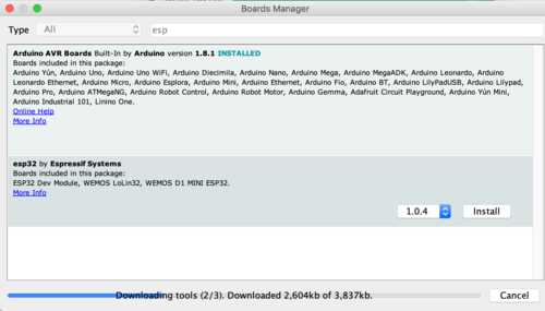
Should download within a minute or two.
NEXT
Back to the Tools dropdown menu make sure the following are set:
Board: "ESP32 Wrover Module"
Upload Speed: "921600"
Flash Frequency:"80 MHz"
Flash Mode:"QIO"
Partition Scheme: "HUGE APP (3MB No OTA/1MB) SPIFFS)"
Core Debug: "None"
Port: "/dev/cu.usbmodem14201" (use ls /dev/cu.* from terminal to find what port yours is connected to)
NEXT
File > Examples > ESP32 > Camera > CameraWebServer
This will open another window with code.
Comment out #define CAMERA_MODEL_WROVER_KIT
And un-comment #define CAMERA_MODEL_AI_THINKER
Assign ssid and password the strings of the name and password respectively of the wifi network you want your board to connect to.
Programming
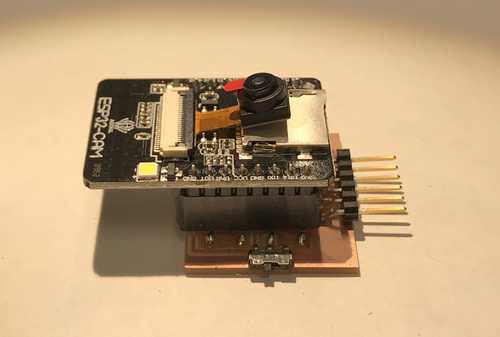
Unlike projects in the past, this board needs to be programmed using an FTDI programmer. We have a couple lying around in the lab, but I have no idea if they work.
At this point you should be able to connect your board to an FTDI programmer like so:
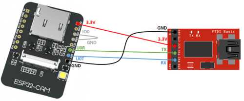
And then the FTDI programmer to your computer via usb.
Flick the switch on your board away from the FTDI header and press the RST button on the underside of the ESP module near the microSD card slot.
At this point click the upload button (double check you have the right serial port selected). It is the left to right arrow in the top left of the window (beside the checkmark).
I keep getting this error:
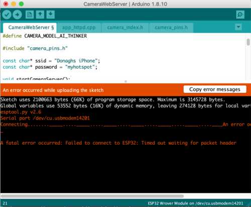
I have tried a couple different connection configurations at this point.
- Board -> 3.3V FTDI to USB cable -> Mac
- Board -> 5V FTDI to USB cable -> Mac
Neither have worked.
Time to look at soldering
Looks good.
Lets check continuity with a multimeter
Everything is connected as it should be EXCEPT for one weird occurrence: the UOT pin is connected to GND (thanks Julia!)
This obviously (...I think...) should not be the case. All the current coming out of this pin will go straight to ground instead of the FTDI Rx pin.
I switch out the ESP32-CAM module with another one and retried loading the code. It worked first time.
This was the output:
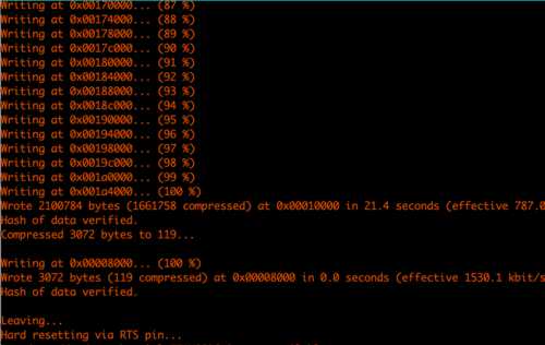
Running
Now I'm going to see if it works!
Steps:
tools > serial monitor- Disconnect
IO0fromGNDby flicking switch on board towards FTDI. - Connect your computer to the same wifi network your board is programmed to connect to
- Hit the reset button on the underside of the board
- Text should appear in the serial monitor you just opened
- Wait until something like this line appears:
Camera Ready! Use 'http://172.20.10.12' to connect - Copy the URL and paste into your browser
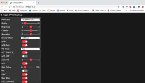
- Scroll down to the bottom of the side menu and click
Start Stream
Success!
I have a few questions about how this system works
- Is the face detection happening on the board or on the webpage?
- How difficult will it be to make this board transmit the coordinates of the box around the face?
- Is this microprocessor quick enough to respond to faces in time? It seems like it is not.