Input Devices
This week we're introduced to a variety of input devices. I experimented with the phototransistor, as I was planning to use it for my final project.
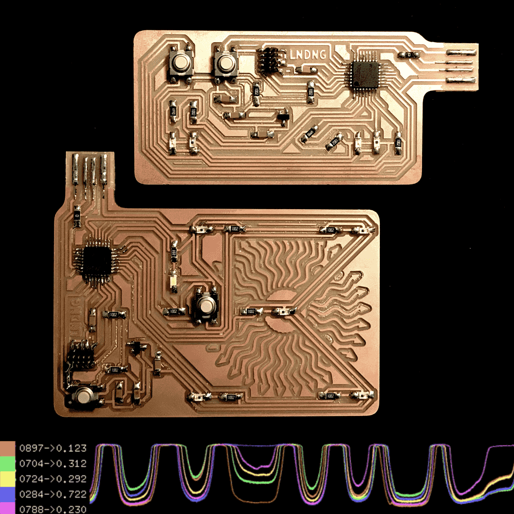
I first made a board with two phototransistors, played with it and got bored, and made another one with five phototransistors. With five phototransistors I can programmatically estimate the position of a light source on the 2D plane. So I wrote an openFrameworks program to read the sensors (via serial communication) and made a bunch of interesting visualization/interactions on my laptop.
Among them, a theramin (video), a piano (video), an illuminated 3D scene (video), as well as some basic data monitor and visualizers. More details about the demos can be found near the bottom of the page.
The openFrameworks code (c++) is available below:
// ofApp.cpp
#pragma once

#include "ofMain.h"
#include "ofxGui.h"

#define N_HIST 8192
#define N_SNSR 5
#define N_WAVE 1024

const float SNSR_X[N_SNSR] = {-1,1,0,1,-1};
const float SNSR_Y[N_SNSR] = {1,1,0,-1,-1};

class ofApp : public ofBaseApp{public:

  ofSerial serial;
  char buff[32];
  int n_buff = 0;
  int comma[N_SNSR];
  int n_comma = 0;
  int vals[N_SNSR];
  float hist[N_HIST][N_SNSR];
  int hist_ptr = 0;

  ofMesh mesh;
  int mesh_n = 16;

  ofFbo fbo;

  ofPolyline vis_abuff;

  ofParameter<bool> b_ther;
  ofParameter<bool> b_pian;
  ofParameter<bool> b_lt3d;
  ofParameter<double> f_dark;

  ofxPanel panel;

  vector<of3dPrimitive> prims;
  ofLight light;
  ofMaterial material;

  void setup(){
    serial.listDevices();
    serial.setup(1, 9600);

    ofPushStyle();
    ofColor data[9]={
      color_code(4),(color_code(4)+color_code(3))/2,
      color_code(3),(color_code(4)+color_code(0))/2,
      color_code(2),color_code(3)+color_code(1)/2,
      color_code(0),(color_code(0)+color_code(1))/2,color_code(1)};
    ofPopStyle();

    for (int i = 0; i < mesh_n; i++){
      for (int j = 0; j < mesh_n; j++){
        mesh.addVertex(ofPoint(i,j,0));

        float x = (float)j/(float)(mesh_n-1) * 3;
        float y = (float)i/(float)(mesh_n-1) * 3;
        mesh.addColor(bicubic(data,3,3,x,y)*0.5+127);
      }
    }
    for (int y=0; y<mesh_n-1; y++){
      for (int x=0; x<mesh_n-1; x++){
        mesh.addIndex(x+y*mesh_n);         // 0
        mesh.addIndex((x+1)+y*mesh_n);     // 1
        mesh.addIndex(x+(y+1)*mesh_n);     // 10
        mesh.addIndex((x+1)+y*mesh_n);     // 1
        mesh.addIndex((x+1)+(y+1)*mesh_n); // 11
        mesh.addIndex(x+(y+1)*mesh_n);     // 10
      }
    }
    fbo.allocate(600,600);

//    setup_prims();

    ofSoundStreamSetup(2, 0);

    panel.setup();
    panel.add(b_ther.set("theramin?", false));
    panel.add(b_pian.set("piano?", false));
    panel.add(b_lt3d.set("3d light?", false));
    panel.add(f_dark.set("dark thresh", 0.03, 0, 0.2));
    panel.setPosition(5, 5);


  }


  void update(){
    while (serial.available()) {
      char c = serial.readByte();
      if (c == '\n'){
        buff[n_buff] = 0;
        for (int i = 0; i < N_SNSR; i++){
          vals[i] = atoi(buff+comma[i]);
          hist[hist_ptr][i] = 1.-(float)vals[i]/1023.;
        }
        hist_ptr = (hist_ptr+1)%N_HIST;
        n_buff = 0;
        n_comma = 0;
      }else if (c == ','){
        buff[n_buff++] = 0;
        comma[++n_comma] = n_buff;
      }else{
        buff[n_buff++] = c;
      }
    }

  }

  ofColor color_code(int k){
    int r = ( (k+1)     & 1) * 155 + 100;
    int g = (((k+1)>>1) & 1) * 155 + 100;
    int b = (((k+1)>>2) & 1) * 155 + 100;
    ofSetColor(r,g,b);
    return ofColor(r,g,b);
  }

  void draw_chart(float x, float y, float w, float h){
    ofPushMatrix();
    ofPushStyle();
    ofTranslate(x,y);
    ofFill();
    ofSetColor(0);
    ofDrawRectangle(0,0,w,h);
    ofNoFill();
    ofSetLineWidth(1);

    for (int k = 0; k < N_SNSR; k++){
      color_code(k);
      ofBeginShape();
      for (int i = 0; i < N_HIST; i++){
        int idx = (hist_ptr+1+i)%N_HIST;
        ofVertex((float)i/(float)N_HIST*w,h-hist[idx][k]*h);
      }
      ofEndShape();
    }

    ofPopStyle();
    ofPopMatrix();
  }

  void quinbary(float* vals, float* x, float* y){
    float s = 0;
    (*x) = 0;
    (*y) = 0;
    for (int i = 0; i < N_SNSR; i++){
      s += vals[i];
    }
    for (int i = 0; i < N_SNSR; i++){
      float f = vals[i]/s;
      (*x) += SNSR_X[i] * f;
      (*y) += SNSR_Y[i] * f;
    }
  }

  void draw_quinbary(float x, float y, float w, float h){
    float u;
    float v;
    float* fval = hist[(hist_ptr-1+N_HIST)%N_HIST];
    quinbary(fval,&u,&v);
    u*=2;
    v*=2;
    ofPushMatrix();
    ofPushStyle();

    ofTranslate(x+w/2,y+h/2);
    ofScale(0.5,0.5);

    for (int i = 0; i < N_SNSR; i++){
      color_code(i);
      ofFill();
      ofDrawCircle(SNSR_X[i]*w, SNSR_Y[i]*h, 12);
      ofNoFill();
      color_code(i);
      ofSetLineWidth(2);
      float z = fval[i];
      ofDrawCircle(SNSR_X[i]*w, SNSR_Y[i]*h, 12+z*60);

    }

    ofFill();
    ofSetColor(255);
    ofDrawCircle(u*w,v*h,20);

    ofPopStyle();
    ofPopMatrix();

  }

  void draw_vals(float x,float y){
    float* fval = hist[(hist_ptr-1+N_HIST)%N_HIST];

    ofPushStyle();
    for (int i = 0; i < N_SNSR; i++){
      color_code(i);
      ofDrawRectangle(x,y+i*20,20,20);
      ofDrawBitmapStringHighlight(ofToString(vals[i],4,'0')+"->"+ofToString(fval[i],3),x+25,y+i*20+14);
    }
    ofPopStyle();
  }


  template <class T>
  T bilinear(T* data, int w, int h, float x, float y){
    x = fmin(fmax(x,0),w-1-FLT_EPSILON);
    y = fmin(fmax(y,0),h-1-FLT_EPSILON);
    int ix = (int)x;
    int iy = (int)y;
    float fx = x - ix;
    float fy = y - iy;
    T z00 = data[iy*w+ix];
    T z01 = data[iy*w+ix+1];
    T z10 = data[(iy+1)*w+ix];
    T z11 = data[(iy+1)*w+ix+1];
    T a = z00 * (1-fx) + z01 * fx;
    T b = z10 * (1-fx) + z11 * fx;
    return a * (1-fy) + b * fy;
  }
  ofVec4f cubicFn(float v){
    ofVec4f n = ofVec4f(1.0, 2.0, 3.0, 4.0) - v;
    ofVec4f s = n * n * n;
    float x = s.x;
    float y = s.y - 4.0 * s.x;
    float z = s.z - 4.0 * s.y + 6.0 * s.x;
    float w = 6.0 - x - y - z;
    return ofVec4f(x, y, z, w) * (1.0/6.0);
  }
  template <class T>
  T bicubic(T* data, int w, int h, float x, float y){
    x = fmin(fmax(x,0),w-1-FLT_EPSILON);
    y = fmin(fmax(y,0),h-1-FLT_EPSILON);

    int ix = (int)x;
    int iy = (int)y;

    float fx = x - ix;
    float fy = y - iy;
    ofVec4f xcubic = cubicFn(fx);
    ofVec4f ycubic = cubicFn(fy);
    ofVec4f c = ofVec4f(ix-1,ix+1,iy-1,iy+1);
    ofVec4f s = ofVec4f(xcubic.x+xcubic.y,xcubic.z+xcubic.w,
                        ycubic.x+ycubic.y,ycubic.z+ycubic.w);
    ofVec4f offset = c + ofVec4f(xcubic.y,xcubic.w,ycubic.y,ycubic.w)/s;
    T s0 = bilinear(data,w,h,offset.x,offset.z);
    T s1 = bilinear(data,w,h,offset.y,offset.z);
    T s2 = bilinear(data,w,h,offset.x,offset.w);
    T s3 = bilinear(data,w,h,offset.y,offset.w);
    float sx = s.x/(s.x+s.y);
    float sy = s.z/(s.z+s.w);
    return (s3 * (1-sx) + s2 * sx) * (1-sy) + (s1 * (1-sx) + s0 * sx) * sy;
  }

  void draw_surface(float x0, float y0){
    float* fval = hist[(hist_ptr-1+N_HIST)%N_HIST];
    float data[9]={fval[4],(fval[4]+fval[3])/2,fval[3],(fval[4]+fval[0])/2,fval[2],(fval[3]+fval[1])/2,fval[0],(fval[0]+fval[1])/2,fval[1]};

    for (int i = 0; i < mesh_n; i++){
      for (int j = 0; j < mesh_n; j++){
        float x = (float)j/(float)(mesh_n-1) * 3;
        float y = (float)i/(float)(mesh_n-1) * 3;
        float z = bicubic(data,3,3,x,y);
        mesh.setVertex(i*mesh_n+j,ofPoint((x-1.5)*120,(y-1.5)*120,z*150));
      }
    }
    fbo.begin();
    ofBackground(0);
    ofPushMatrix();
    ofTranslate(fbo.getWidth()/2,fbo.getHeight()/2);
    ofRotateXRad(M_PI/4);
    mesh.drawWireframe();
    ofPopMatrix();
    fbo.end();
    fbo.draw(x0,y0);
  }


  void draw(){
    ofBackground(50);


    draw_surface(400,50);

    if (b_lt3d){
      draw_prims();
    }
    draw_quinbary(50,300,300,300);

    if (b_pian || b_ther){
      draw_ao();
    }

    draw_chart(0,ofGetWindowHeight()-100,ofGetWindowWidth(),100);
    draw_vals(0,ofGetWindowHeight()-100);

    panel.draw();

    ofSetWindowTitle(ofToString(ofGetFrameRate()));
  }

  void draw_ao(){
    ofPushStyle();
    vis_abuff.draw();
    ofPopStyle();
  }

  double frq;
  double amp;
  double phase = 0;
  double  waveform[N_WAVE];
  int n_wave = 1024;
  double phases[N_SNSR] = {0};
  double amps[N_SNSR] = {0};
  double key_freq[N_SNSR] = {261.63, 293.67, 329.63, 392.00, 440.00};

  void audioOut( float * output, int bufferSize, int nChannels ) {
    float* fval = hist[(hist_ptr-1+N_HIST)%N_HIST];
    double sampleRate = 44100;

    if (b_ther){

      double frq_targ = (fval[3]+fval[4])/(fval[0]+fval[1]+fval[3]+fval[4])*800+40;
      frq = frq * 0.95 + frq_targ * 0.05;

  //    n_wave = (int)((fval[1]+fval[3])/(fval[0]+fval[1]+fval[3]+fval[4])*61+3);
      double amp_targ = ofClamp( (fval[1]+fval[3])/(fval[0]+fval[1]+fval[3]+fval[4]) - 0.25, 0, 0.5);

  //    float amp_targ = (fval[0]+fval[1]+fval[2]+fval[3]+fval[4])/5.0;
      amp = amp * 0.95 + amp_targ * 0.05;
      double waveformStep = (M_PI * 2.) / (double) n_wave;

      for(int i = 0; i < n_wave; i++) {
        waveform[i] = sin(i * waveformStep);
      }

      double phaseStep = frq / sampleRate;
      for(int i = 0; i < bufferSize * nChannels; i += nChannels) {
        phase += phaseStep;
        int waveformIndex = (int)(phase * n_wave) % n_wave;
        output[i] = waveform[waveformIndex]*amp;


      }
    }
    if (b_pian){

      double waveformStep = (M_PI * 2.) / (double) n_wave;
      for(int i = 0; i < n_wave; i++) {
        waveform[i] = sin(i * waveformStep);
      }

      for (int k = 0; k < N_SNSR; k++){
        if (fval[k] < f_dark){
          double amp_targ = (f_dark - fval[k])/f_dark;
          amps[k] = amp_targ * 0.1 + amps[k]*0.9;
        }else{
          amps[k] = amps[k]*0.9;
        }
        double phaseStep = key_freq[k] / sampleRate;
        for(int i = 0; i < bufferSize * nChannels; i += nChannels) {
          phases[k] += phaseStep;
          int waveformIndex = (int)(phases[k] * n_wave) % n_wave;
          output[i] += waveform[waveformIndex]*amps[k];
        }
      }
    }

    vis_abuff.clear();
    for(int i = 0; i < bufferSize * nChannels; i += nChannels) {
      vis_abuff.addVertex(ofMap(i,0,bufferSize-1,0,1024),ofMap(output[i],-1,1,100,568));
    }

  }

  #define prim_rand_dim ofRandom(60,80)
  void setup_prims(){
    ofSetSmoothLighting(true);
    light.setDiffuseColor( ofFloatColor(1.f,1.f,1.f) );
    light.setSpecularColor( ofFloatColor(1.f, 1.f, 1.f));
    material.setShininess( 120 );
    material.setSpecularColor(ofColor(255, 255, 255, 255));

    for (int i = 0; i < 10; i++){
      ofIcoSpherePrimitive p;
      p.setResolution(1);
      p.setRadius(prim_rand_dim);
      prims.push_back(p);
    }
    for (int i = 0; i < 10; i++){
      ofConePrimitive p;
      p.setResolution(7,1,1);
      p.set(prim_rand_dim/2,prim_rand_dim);
      prims.push_back(p);
    }
    for (int i = 0; i < 10; i++){
      ofBoxPrimitive p;
      p.set(prim_rand_dim,prim_rand_dim,prim_rand_dim);
      prims.push_back(p);
    }
    for (int i = 0; i < prims.size(); i++){
      prims[i].rotateRad(ofRandom(0,M_PI*2),1,0,0);
      prims[i].rotateRad(ofRandom(0,M_PI*2),0,1,0);
      prims[i].setPosition(ofRandom(-400,400),ofRandom(-200,100),ofRandom(-300,200));
    }
  }

  float u_sm = 0;
  float v_sm = 0;
  bool did_prim_setup = false;
  void draw_prims(){
    if (!did_prim_setup){
      did_prim_setup = true;
      setup_prims();
    }
    float u;
    float v;
    float* fval = hist[(hist_ptr-1+N_HIST)%N_HIST];
    quinbary(fval,&u,&v);
    u*=2;
    v*=2;

    u_sm = u_sm * 0.9 + u * 0.1;
    v_sm = v_sm * 0.9 + v * 0.1;

    ofPushStyle();
    ofBackground(0);
    ofPushMatrix();
    ofTranslate(ofGetWindowWidth()/2,ofGetWindowHeight()/2);
    ofRotateXRad(M_PI/4);
    ofRotateYRad(M_PI/4);
    ofEnableDepthTest();
    ofEnableLighting();
    light.enable();

    light.setPosition(ofGetWindowWidth()/2+u_sm*ofGetWindowWidth(),ofGetWindowHeight()/2+v_sm*ofGetWindowHeight(),300);

    for (int i = 0; i < prims.size(); i++){
      material.begin();
      prims[i].draw();
      material.end();
      ofSetColor(0);
      prims[i].setScale(1.01f);
      prims[i].drawWireframe();
      prims[i].setScale(1.f);
    }

    ofDisableLighting();
    ofDisableDepthTest();
    ofPopMatrix();
    ofPopStyle();
  }

  void keyPressed(int key){}
  void keyReleased(int key){}
  void mouseMoved(int x, int y ){}
  void mouseDragged(int x, int y, int button){}
  void mousePressed(int x, int y, int button){}
  void mouseReleased(int x, int y, int button){}
  void mouseEntered(int x, int y){}
  void mouseExited(int x, int y){}
  void windowResized(int w, int h){}
  void dragEvent(ofDragInfo dragInfo){}
  void gotMessage(ofMessage msg){}
};
On the board is a simple arduino program that reads the sensors and sends serial:
void setup() {
  pinMode(11,OUTPUT);
  pinMode(2, INPUT);
  pinMode(3, INPUT);
  pinMode(4, INPUT);
  pinMode(5, INPUT);
  pinMode(6, INPUT);
  pinMode(7, INPUT);
  Serial.begin(9600);
  for (int i = 0; i < 7; i++){
    digitalWrite(11,i%2);
    delay(500);
  }
}
void loop() {
  if (digitalRead(7) == LOW){
    digitalWrite(11,HIGH);
  }else{
    digitalWrite(11,LOW);
  }
  Serial.print(analogRead(2));
  Serial.print(",");
  Serial.print(analogRead(3));
  Serial.print(",");
  Serial.print(analogRead(4));
  Serial.print(",");
  Serial.print(analogRead(5));
  Serial.print(",");
  Serial.print(analogRead(6));
  Serial.print("\n");
}
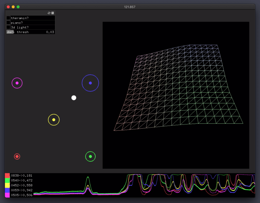
A screenshot:
Design
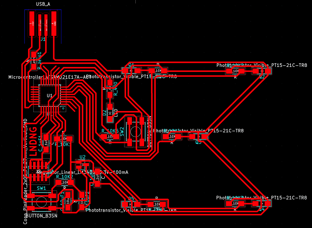
I made a schematic with two phototransistors, two LED's and one button. My plan was to affect the phototransistors' readings with the LED's, and use the button to control the LED's.
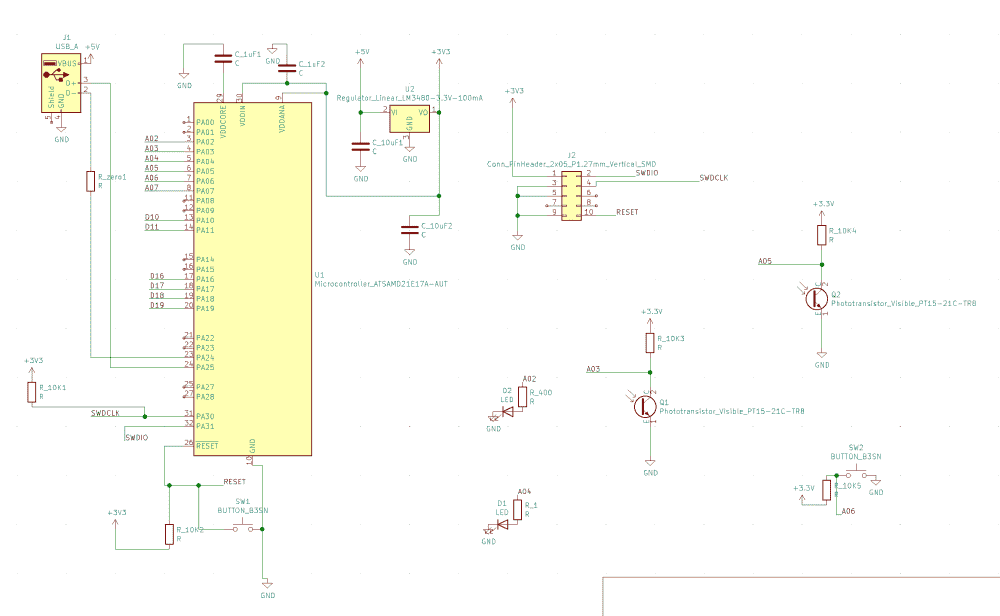
Since previous weeks of PCB-making, I've developed an “optimal” layout for SAMD21E boards, which is compact and require only one jump (or zero jump if smaller pads for the microcontroller is used). So every time I make a new board, I copy over that portion of the board. Then I use KiCAD to make a very rough layout with the new components, just to solve the routing puzzle, and where aesthetic is not a concern.
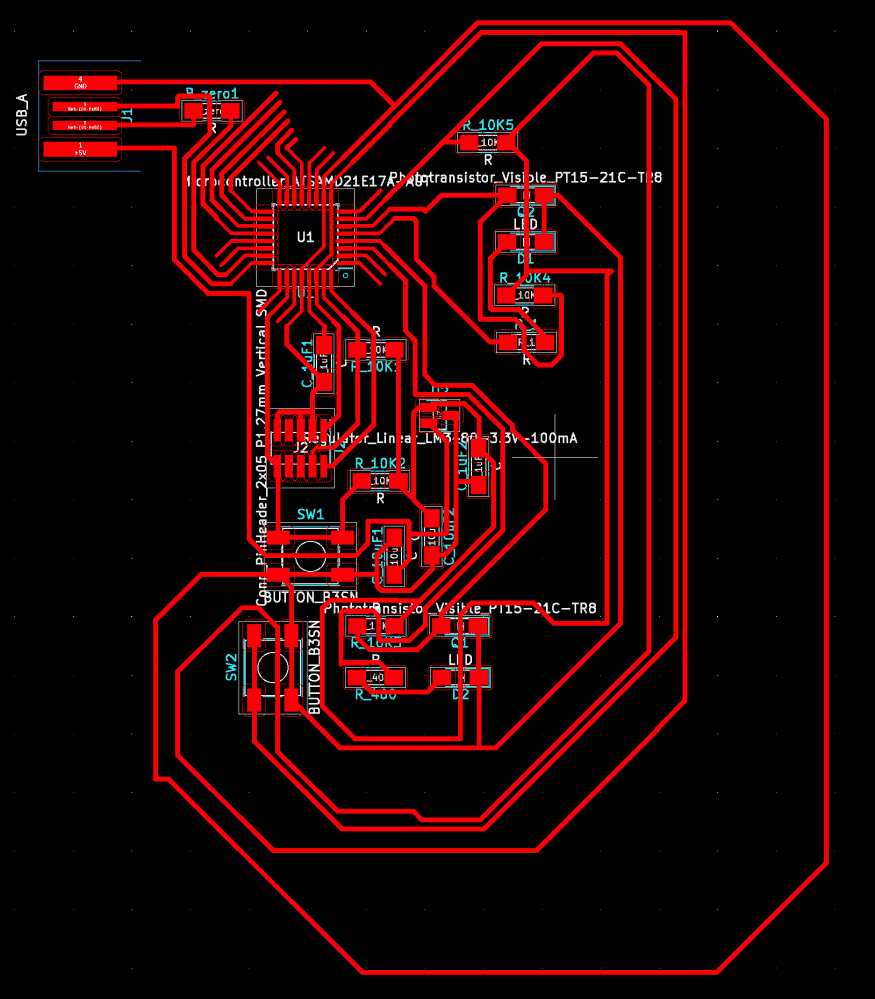
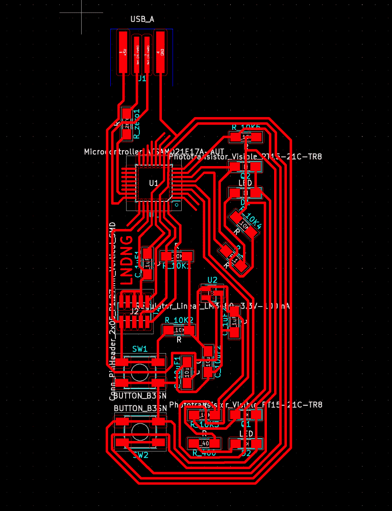
Then I make a screenshot, delete the components, and redo the process in a compact and good looking way.
You can see that I've spaced the phototransistors such that they're aligned on the X-axis while being as far apart as possible on the Y-axis. This way the readings won't be too similar that the point of having two of them is lost; and I can move a light source or an object blocking the light source along the Y-axis and observe how the readings change.
Fabrication
Having designed the board on Wednesday night, I started to fabricate the board on Thursday. There was already a half-used borad in the PCB milling machine, so I tried to reuse that. But the board was taped down too sloppily by the previous person, that it started jiggling when being milled. Moments later the tip of the endmill disappeared, and I realized that I broke the endmill. I used to be pretty proud that I've never broken one, but now I can no longer say that.
I taped down a new board and it milled beautifully, so I started soldering it. Last time it took me some two hours to solder the SAMD21, because the pins/pads are so incredibly thin and tightly spaced. But this time I became so good at soldering that I managed to solder the microcontroller in five minutes. I finished soldering the rest of the board in another couple of minutes.
My method was to just smudge some flux on each pad, melt a drip of solder onto the iron, and scrape it onto the pins/pads. Another trick that greatly reduced my soldering time (and frustration) was the one prof. Neil explained during lecture: when using the braid to remove solder, there needs to be some solder already on the iron or the braid. I've always been doing it wrong until then; previously I even took care to wipe the iron and use clean sections of the braid, which worked very badly for me. Now with this new trick removing solder with the braid became a breeze.
It didn't took too many trials before I managed to bootload the board. However, when I programmed the board to report the sensor readings via serial, it seems that the range only varied between 980 and 1023, when I obscure and un-obscure the phototransistors with my finger. I was hoping that it could cover the entire range of 0-1023. So I asked the question on our section's issue tracker. Classmate Jason recommanded changing the resistor to a smaller one, while TA's Andres and Anthony pointed out that the phototransistors were soldered the wrong way. I decided to try flipping the phototransistors first.
And it turned out that this fixed the problem, and I was getting a good range of reading. The reason I connected the phototransistors wrongly in the first place, was that I thought they were like LED's, and the little green mark on the package denotes cathode and should point to the ground. However, it turns out that phototransistors are the “reverse” of LED's, and the green mark should point toward the analog pin instead. Who would have thought of that??
More!
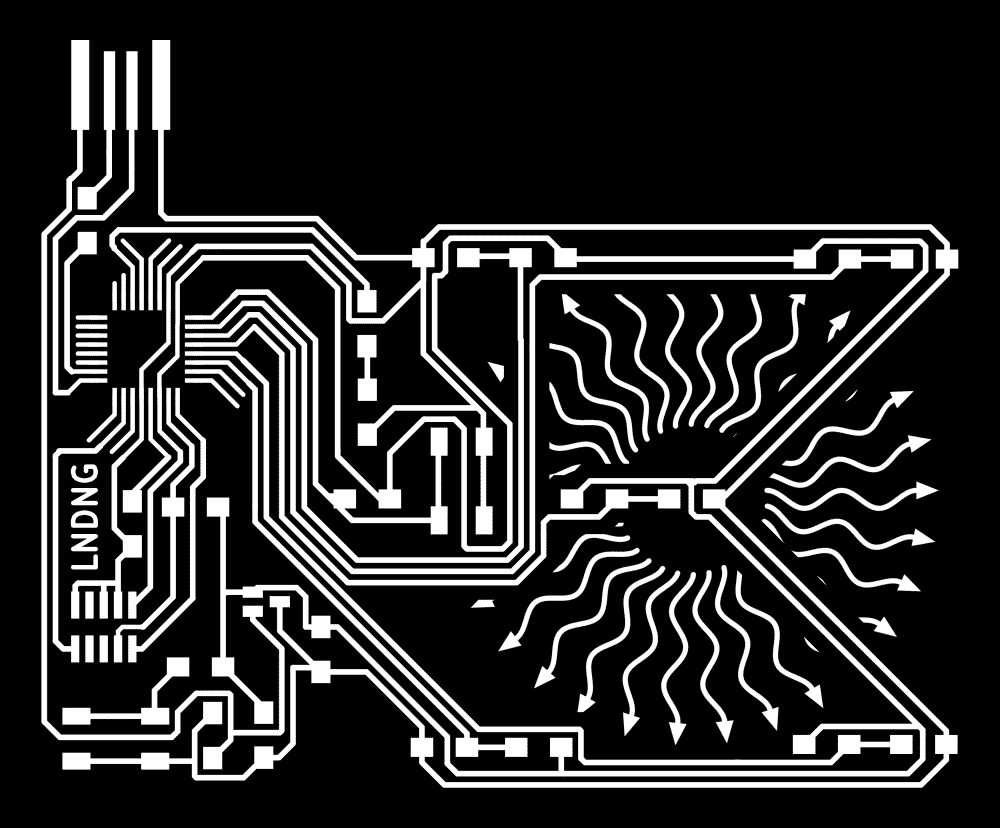
I was soon a bit bored with playing the 2-transistor board. Plus, it seemed that LED's were too dim to significantly affect the transistors' readings. Therefore, I came up with a new idea, of having a matrix of phototransistors, which should allow me to locate the light souce on the 2D plane programmatically.
Originally I was planning to have a 4x4 gird of them, but soon realized that there were only 6 analog pins on the SAMD21. Therefore, I settled with placing 5 phototransistors: 4 on each corner of a square, and one in the middle.
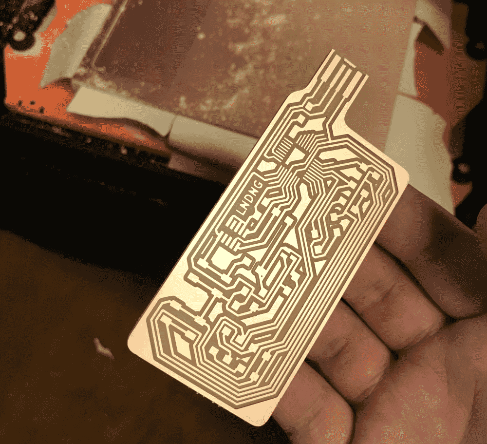
The board now looked a bit too spacious and empty, a kind of look that I dislike. so I decided to put some decorations there.
I wrote some super trivial and sloppy code in p5.js to draw some simple ray patterns. Code below:
const N = 500;
const N_CAND = 50;
function ray(x0,y0,x1,y1){
  let a = atan2(y1-y0,x1-x0);
  let n = ~~(dist(x0,y0,x1,y1)/2);
  strokeWeight(10);
  stroke(255);
  noFill();
  beginShape();
  for (let i = 0; i < n; i++){
    let t = i/(n-1);
    let x = lerp(x0,x1,t);
    let y = lerp(y0,y1,t);
    let z = cos(t*PI*4)*12;
    let u = x + cos(a-PI/2)*z;
    let v = y + sin(a-PI/2)*z;
    vertex(u,v);
  }
  endShape();
  push();
  translate(x1,y1);
  rotate(a);
  noStroke();
  fill(255);
  triangle(30,-12,0,-24,0,0);
  pop();
}
function setup() {
  createCanvas(800,800);
  background(0);
  const W = width;
  const H = height;
  translate(W/2,H/2);
  strokeCap(SQUARE)
  let n = 30;
  for (let i = 0; i < n; i++){
    let t = i/n;
    let a = PI*2*t;
    let x0 = cos(a)*100;
    let y0 = sin(a)*100;
    let x1 = cos(a)*300;
    let y1 = sin(a)*300;
    ray(x0,y0,x1,y1);
  }
}
Then I composited the images in photoshop. I dilated the traces to subtract them from the decoration, such that the decoration was clearly separated and could not become accidental bridges electrically.
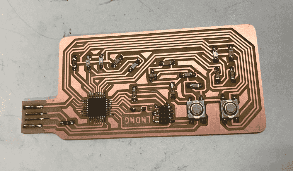
I fabricated the new board on Sunday. It took an hour or so to mill, but much less time to solder. However, I couldn't quite get it to bootload. I soon discovered that I forgot to put a trace from the reset button to the reset pin on the header. In KiCAD, the white line indicating the missing trace was very thin, and because it was entirely vertical, I failed to see it. As I was too confident with my layout skills, I didn't even bother to run the “bug-finding” feature in KiCAD. Now I had to pay the price.
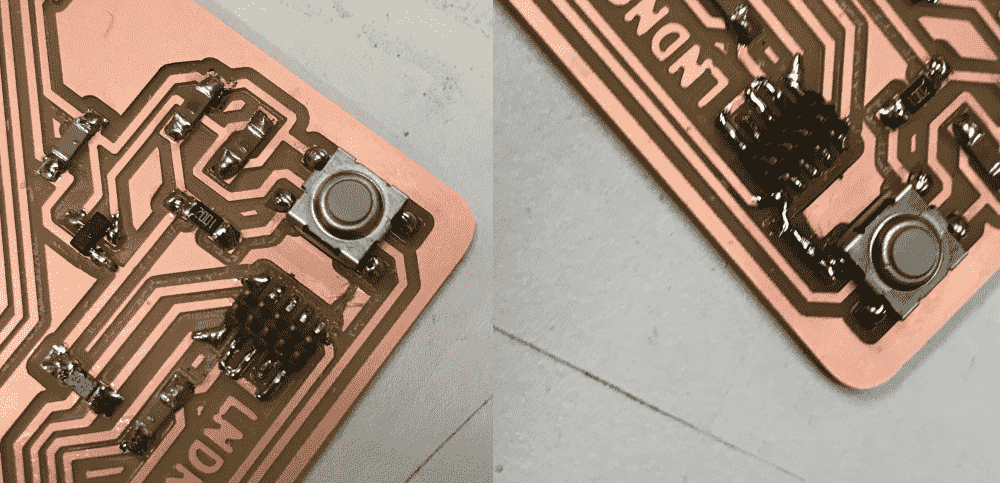
So I first carved out a groove on the copper with a razor, and then put a large amount of solder on the ridge to act as a bridge. My ugly hack worked!
The demos
I thought about the algorithm I should use to locate the light source on the 2D plane with readings from the five sensors. Initially, I was inspired by barycentric coordinates, which allows locating a point in relation to a triangle. So I thought, perhaps I can devide the area into four right-angled triangles, and first decide which of the four triangles the light source is currently in, and then imploy barycentric formulae. However, this caused the estimated location to jump abruptly from one triangle to another, the moment the trianlge's score exceed its neighbor.
I realized that I was overthinking it. Instead of dividing into triangular regions, I just blended the coordinate of all five sensors weighted by their brightness. This looked much smoother, but the estimation tends to bias toward the middle, which is expectable. I simply multiplied the vector by a factor of 2, and found the result quite believable.
Next I went on to fit a 3d surface to the 5 points. Initially I thought about solving some system of equations, but decided it was too much headache. Instead, I faked 4 more datapoints by taking the midpoint of adjacent vertices, creating a 3x3 gird. Then I simply applied bicubic interpolation to get the smooth surface. It worked reasonably well.
Finally I added a couple simple demos. The fun part was that I made the sound synthesizers by directly writing an array of floats to the laptop's sound buffer, something I kinda understood before but never tried personally.
A theramin:
A (5 key) piano:
A 3D scene where the position of the virtual light source is controlled by that of the real light source.
Downloads
My design files (KiCAD) can be downloaded below: