Networking and Communications
This week we're asked to try out either wired or wireless communication between boards. Since I was not particularly fond of wireless communication (I found them unreliable and a pain to debug), I decided to play with serial. However, it proved to be too little of a challenge for me, so I tried out bluetooth too. I was satisfied with the extra headaches.
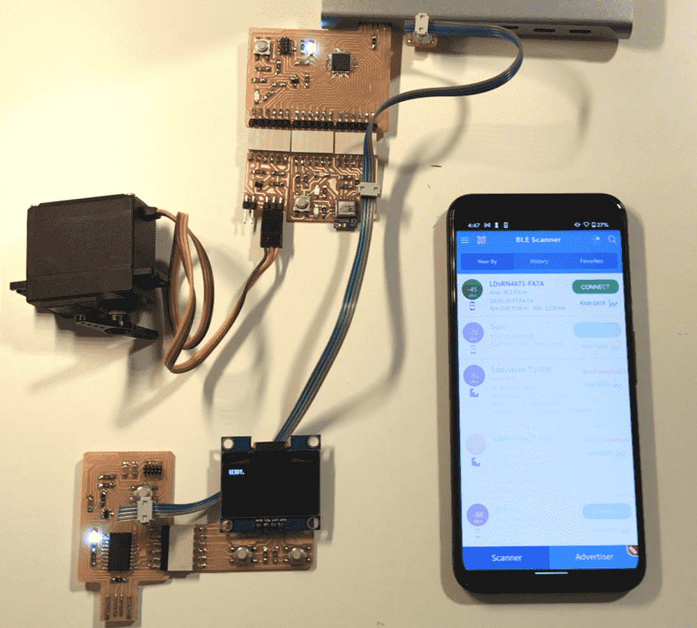
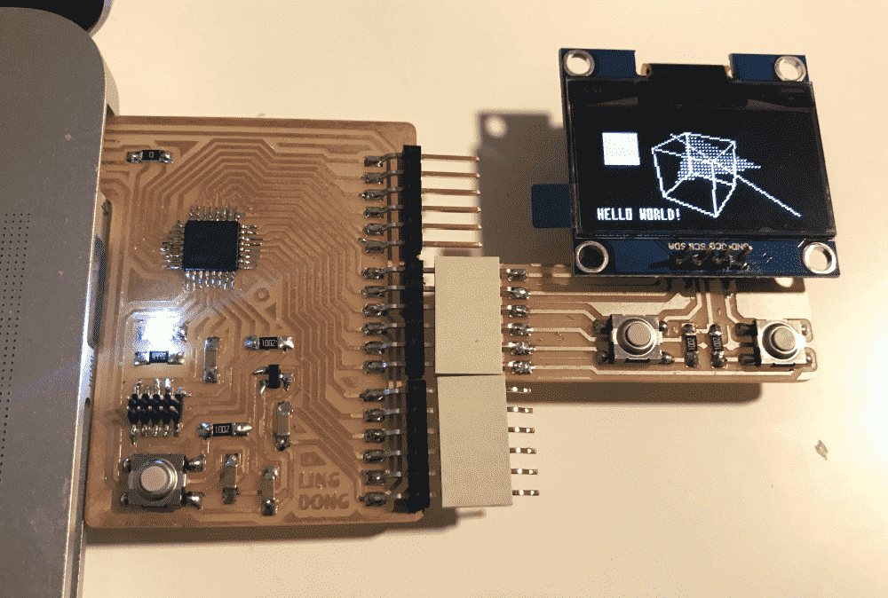
In the first video below, you can see how I used a phone to talk to the RN4871 via bluetooth, which talks to a SAMD21E microcontroller, which controls a servo and also pass on the command to a SAMD11D microcontroller via serial, which controls a OLED display via I2C.
In this video below, you can see how I wrote a web interface for my bluetooth setup, and how I managed to send a 32x32 image via bluetooth. Unfortunately the webpage only works on my laptop; the phone has too small a buffer for BLE data.
Design
Since I initially planned to play with serial, I figured that it would be a good idea to make more boards, even though I already have quite a stash of them from previous weeks.
I noticed that our section was nearly out of SAMD21E's and SAMD11C's. They're probably so popular because they're featured in the professor's and TA's demos, which we tend to copy our designs from. In comparison, the SAMD11D's are very unloved, the drawer is packed full of them and it seems that nobody uses them.
So I decided to give the SAMD11D's a chance. In the end I found them very lackluster: they're basically SAMD11C's in a fatter package. Though it has more pins it has just as little flash as a SAMD11C. The serial USB library still takes up 90% of the space, which means that if my program is so complex that it requires that many pins, it probably won't fit in the flash. If I get rid of the USB library, it seems that I'll always need a programmer to re-program it, which isn't exactly convenient.
They aren't easy to route either. The different type of pins are somewhat scattered and hard to form a “bus” that flows through the board, like I've been doing with my favorite microcontroller so far, the SAMD21E.
In the end, I had to use two 0-ohm resisters for jumps, my worst record. I also used a “riskier” track width 0.45mm instead of my usual 0.5mm.
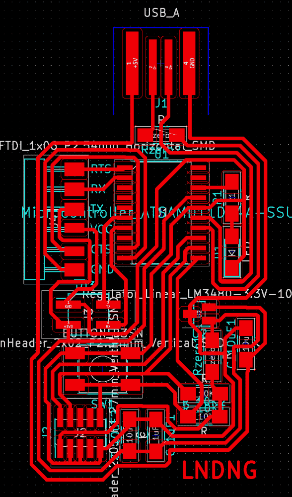
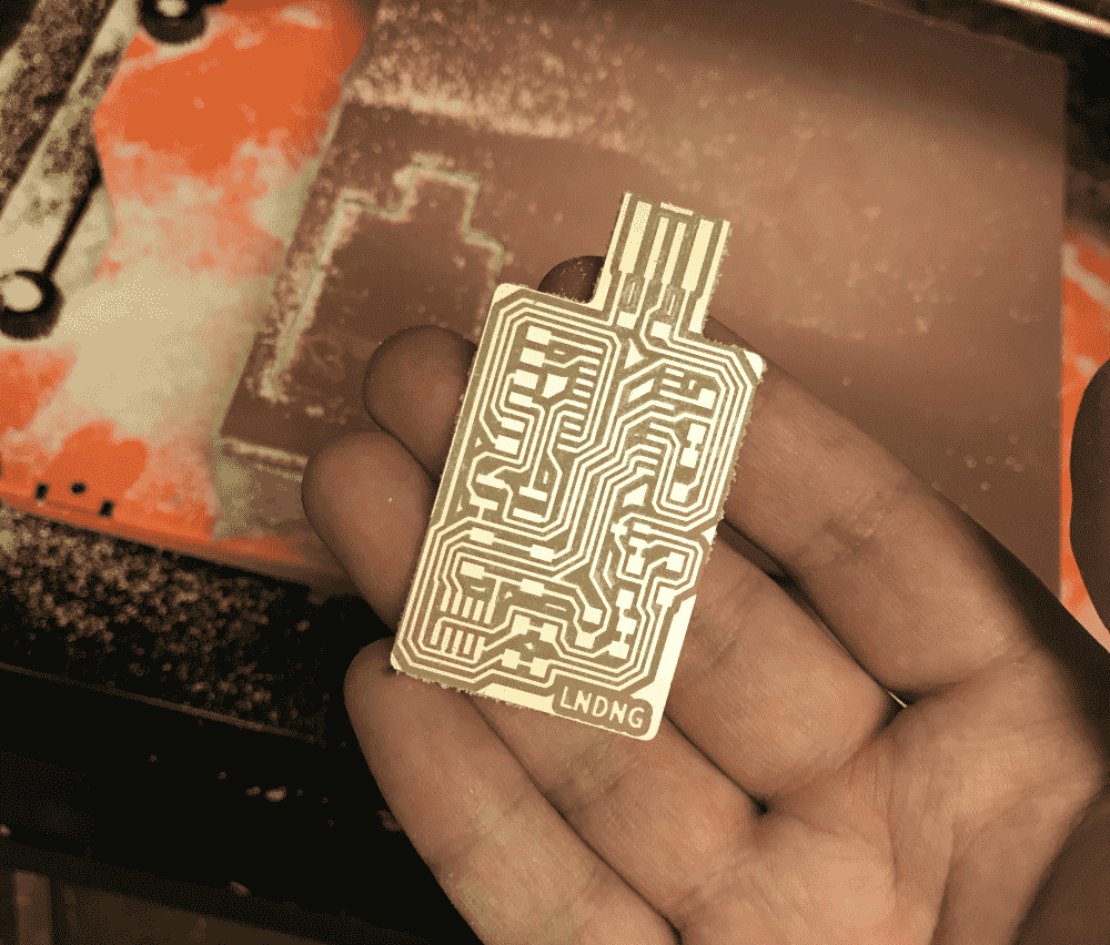
As you can see my design is a “semi-breakout board”. It has four 2.54mm pins dedicated for serial (TX, RX, plus power, so that only one board in a series needs to be plugged in), as well as a row of six FTDI headers for unspecified purpose. The FTDI headers are arranged in the same way as one of the three on my other SAMD21E breakout board, (SDL, SCA, GND, 3.3V, analog, analog), so any “module” I make for that board is also compatible with this one.
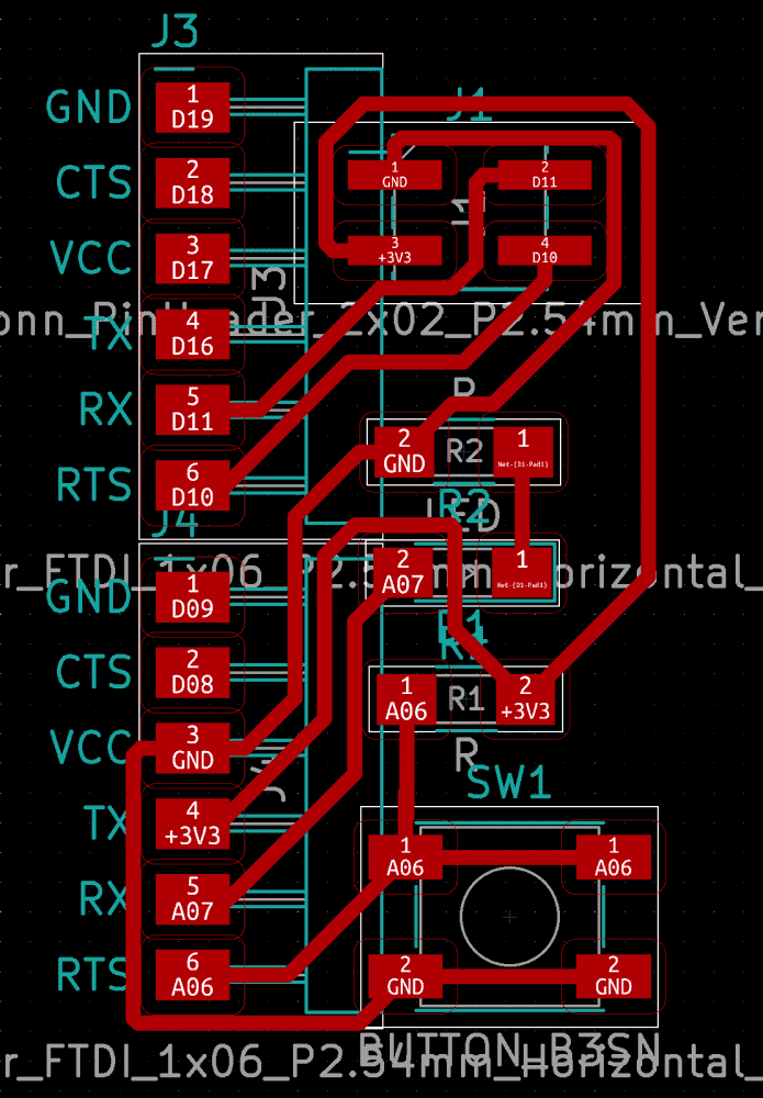
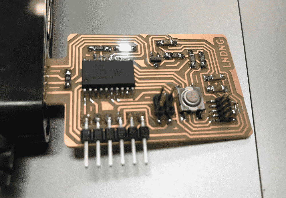
I then designed a serial module for my other SAMD21E breakout board, for it to talk to this SAMD11D semi-breakout board. It has some random LED's and buttons, so I can control and indicate something, exact functions of which to be decided later.
Fabrication
As I've fabricated so many boards (almost 20 by now), perfectly milled boards only make me only very slightly happy.
As I've bootloaded so many boards, boards bootloaded in one shot also make me only very slightly happy.
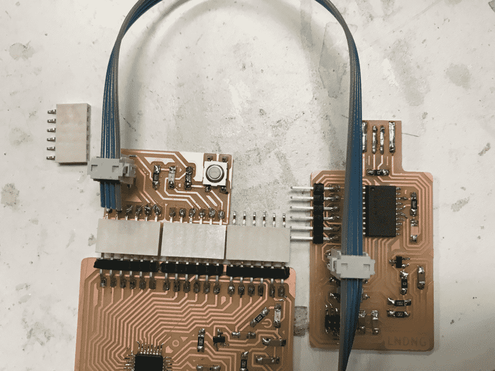
However, when I connected my boards with a ribbon cable and plugged one of them into USB, the boards only got powered for a fleeting moment, after which both died, as indicated by the fading LED power indicator.
It seemed that I had to have both boards plugged into USB power, and that the 3V3 from the ribbon cable was not enough to support the two of them.
I thought that the dying boards, how the shimmering lights flee their “eyes”, was a rather poetic sight to look at. However, when I showed it to classmate Reina, she promptly pointed out that I should be running 5V in the ribbon cable instead of 3V3, otherwise the regulator wouldn't have anything to regulate with.
I suddenly felt less poetic and more dumb. I just produced two pieces of garbage! Time to mill two new boards.
Getting Serial to Work
Then I realized that I should make sure the serial on the boards are working first, lest I waste more time fabricating garbage. So I plugged both into USB, and started frobbing at Arduino IDE.
And it was not working. Firstly, on the SAMD11D pin map, I could see that the TX/RX pins I was using were labeled “2”, so supposedly, I should be using Serial2 in Arduino IDE (Terrible design on Arduino's side by the way, why can't we have Serial mySerial(2);? Arduino users are dabbler programmers maybe, but to assume that they don't know how to instantiate is just strange. Perhaps there's a better reason. Luckily, C++ is decent enough to keep the C macros, so I just #define mySerial Serial2).
Anyways, the problem was that Arduino IDE didn't even think that Serial2 exists. It recognizes Serial or Serial1, but Serial2 is just a compile error. Time to copy-paste random code grabbed from the Internet!
This piece of random code looked particularly plausible:
Uart Serial2(&sercom2, PIN_SERIAL2_RX, PIN_SERIAL2_TX, PAD_SERIAL2_RX, PAD_SERIAL2_TX);
But it didn't quite work. The sketch compiled OK, but apparently no data was transmitted. It seemed that there were other pieces of random code that I needed to copy too:
pinPeripheral(14, PIO_SERCOM);
pinPeripheral(15, PIO_SERCOM);
void SERCOM2_Handler(){
  Serial2.IrqHandler();
}
But no luck with those either. Same, silent failure as before. I thought, perhaps I could probe the RX/TX lines with an oscilloscope and see if anything shows up. The problem was that I didn't know how to use one, so classmate Justin kindly helped me. However, every thing we probed, circuit or otherwise, always showed up as the same sin wave. Justin speculated that the scaling needed to be adjusted, using the myriad of knobs on the machine. I decided to try out software-simulated serial first.
It turned out the SoftSerial Arduino library only works for AVR boards. What?? And the internet seemed to be OK with the fact. Just use hardware serial, they say.
I was a tad frustrated and started clicking around in the Arduino IDE to see if there was anything I could frob with in the GUI's. Wait a moment, what's this??!
ONE_UART_ONE_WIRE_ONE_SPI
What? only one UART? I do need more!
TWO_UART_ONE_WIRE_NO_SPI
Much better. Who cares about SPI's? I uploaded the sketch, and guess what, my serial started working beautifully.
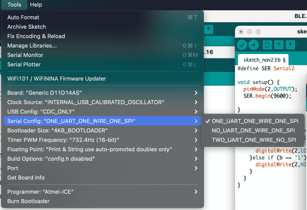
So I believe that since I was using Serial2, the second pair of serial pins, I need to enable two UART's. It makes sense, since many pins on SAMD are multi-functional, so this menu option lets you select which functions to dedicate these pins to. I believe that after that, when you hit verify or upload, the SAMD library for Arduino gets re-compiled, and the identifier Serial2 becomes globally defined.
The same is the case for SAMD21E's. You can select one to four UART's, at the price of having less I2C's and SPI's.
Below you can see the synchronous blink of the SAMD11D and the SAMD21E, synchronized by serial communication.
The codes are super simple:
//SERIAL.A.ino
#define SER Serial1

void setup() {
  pinMode(28,OUTPUT)
  SER.begin(9600);
}

void loop() {
  digitalWrite(28,LOW);
  SER.print('0');
  delay(500);
  digitalWrite(28,HIGH);
  SER.print('1');
  delay(500);
}
//SERIAL.B.ino
#define SER Serial2

void setup() {
  pinMode(2,OUTPUT);
  SER.begin(9600);
}
void loop() {
  if (SER.available() > 0) {
    int b = SER.read();
    if (b == '0'){
      digitalWrite(2,LOW);
    }else if (b == '1'){
      digitalWrite(2,HIGH);
    }
  }
}
The only nuisance is that since I'm using two different types of microcontrollers (21E and 11D), I constantly need to switch multiple settings (Board, Serial, Port) back and forth in Arduino IDE.
Getting 5V
Now that I got the serial working, it's finally time to mill new boards sans the power problem.
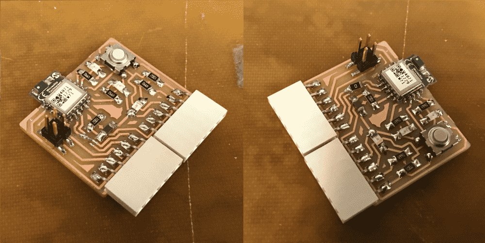
Below you can see the almost identical “twins” of SAMD11D boards; the bottom one has the 3V3 pin fixed to connect to 5V instead. Can you spot the difference?
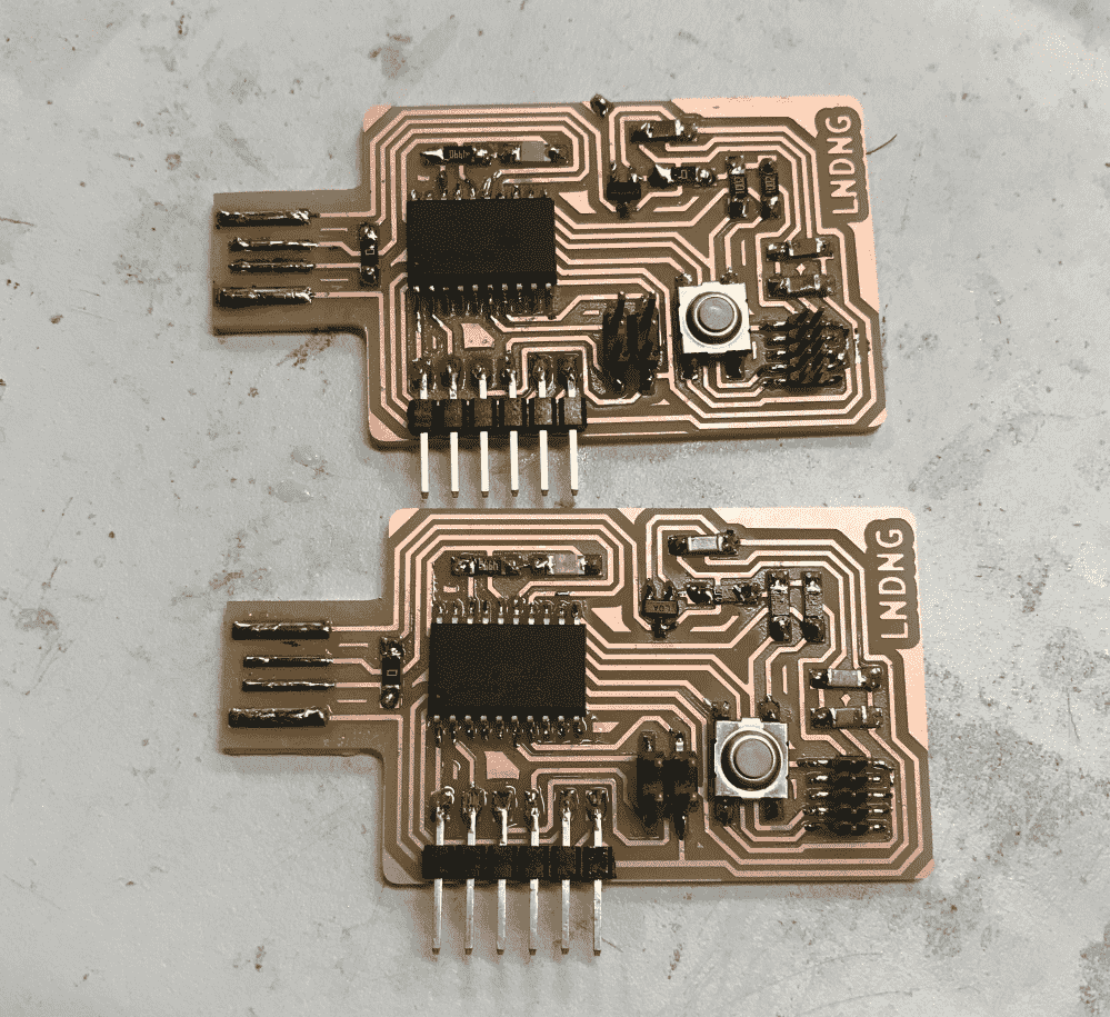
I verified that I could now power many boards via one ribbon cable.
SAM > AVR
Only two boards talking didn't sound fun enough, so I decided to bring in a third. Too lazy to design a new one or fabricate my SAMD11D design a third time, I decided to mill prof. Neil's serial demo board.
The board uses a AVR (Attiny45) microcontroller, which I had never made or used before, so I figured that it might be a good chance to try it out. It was a tiny board with few elements so I fabricated it in a matter of minutes.
However, I was greeted with many troubles. Firstly, the board design has no USB plug, so I needed another way to plug it in. I found that the 6 pin female thing on Atmel-ICE seemed to fit the 6-pin male thing on the board. I also switched the Atmel-ICE cable to its AVR slot. However, the green light on Atmel-ICE, which usually indicates that Atmel-ICE approves of whatever connected into it, did not light up.
Nevertheless, I fired up Arduino IDE to see what happens. Obviously I would need AVR board definitions like I did with the SAM ones, so I looked up the Fab Arduino ATTINY Guide on MTM. Interestingly, the Attiny45/85 is not included in the recommended board manager. Huh? Time to try out random board managers from the Internet.
So I found this package from David A. Mellis, simply called “attiny”, which includes the 45/85. However, after I installed and configured it and tried to upload an empty sketch, Arduino spit out pages of errors about jtag or something (which is strange, since I was not even using the jtag header). It seemed that Arduino is using something called “avrdude” underneath, and this “dude” was not very happy!
As a test, I unplugged the board and tried uploading again, and the error messages were the same. This indicated that the board was not even detected.
Then I remembered that the Atmel-ICE cannot power boards, even it though it wants GND and V pins. So I needed another way of powering the board, but how? I looked at the design again and realized that I could probably power it through the TX/RX cable, for that 4 pin header includes GND and V too. So I connected the tiny board to my D11D which was powered by USB, and Atmel-ICE's green light finally lit up.
However, Arduino IDE was still giving me strange errors about “claiming interface”. It turned out, that the Internet says, avrdude cannot program through Atmel-ICE under macOS, and there's a scary way to fix it, which involves disabling SIP (system integrity protection, not to be confused with ISP, in-system programming, or SPI, serial peripheral interface). What? But edbg doesn't seem to have this problem (edbg still has issues with macOS though, e.g. I can't use a fab programmer with it on a mac, only Atmel-ICE works). Maybe the authors of avrdude could chat with those of edbg to see how they got it to work.
So I ended up programming the tiny board using Windowses and Linuxes. Another interesting problem was that the board didn't seem to respond to Arduino commands digitalWrite() and pinMode(), and I had to use prof. Neil's register bit operations to control the LED.
However, I still couldn't get the tiny board to talk to my other two boards via serial. Then I suddenly also realized that the AVR's are using 5V, does that make its TX/RX pins also send 5V and expect 5V? Will the 5V from the pins kill my 3V3 SAM's? I figured that I should stop risking it and call it a day.
In summary, I had a bad experience with the AVR, and was glad that I've been sticking to SAM's so far.
Bluetooth
Since I've got all the serial stuff figured out on Thursday, I decided to try some wireless stuff, perhaps those would be more of a challenge.
So I looked through the shop's drawers and the course website to see what I felt like doing. There was a bluetooth module, labelled RN4871. It only requires ground, power, TX and RX, nice and simple.
I designed a small circuit to connect it to my SAMD21E breakout board.
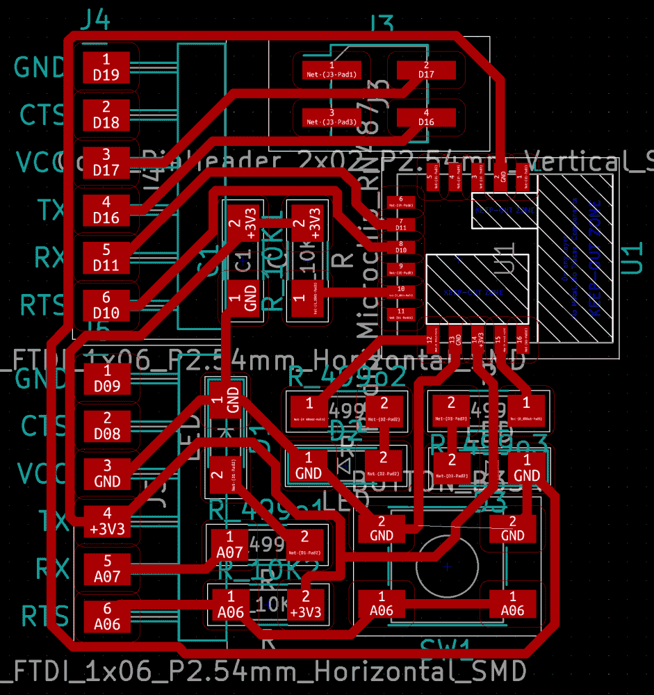
There are 16 pins on RN4871. There are two GND's, one V, a RST, RX, TX, those I understood -- but why are there so many other pins? Initially I planned to expose all the other pins via pin headers, so in case they're useful, I could figure out later. But that made the routing quite messy, so I decided to actually read the datasheet.
Among pages of cryptic jargons, I found two pins that I could understand:
P0_2
LED0: Provides indication whether the module is in On/Off mode.
and
P2_7
UART_TX_IND output pin. Provides indication if RN4870 is transmitting
 to host MCU over UART. Pulled low before UART TX begins and pulled
 high after UART TX is over.
So basically I can connect LED's to them as indicators, cool! Later I found out that the LED's should connect to power instead of ground on the other end, since the pins are high by default. But that wasn't much of an issue, since they could still blink, just with inverted light/dark. I even liked that way better.
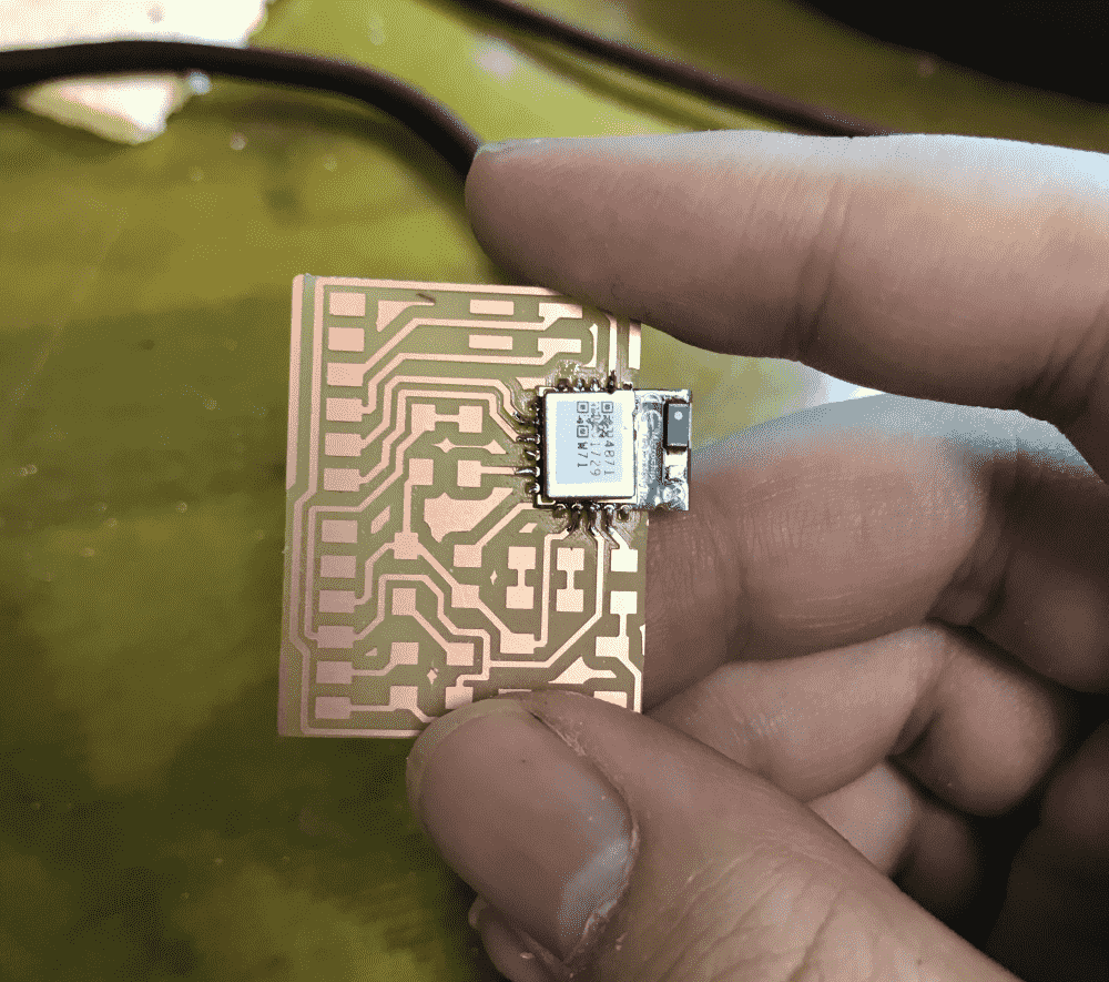
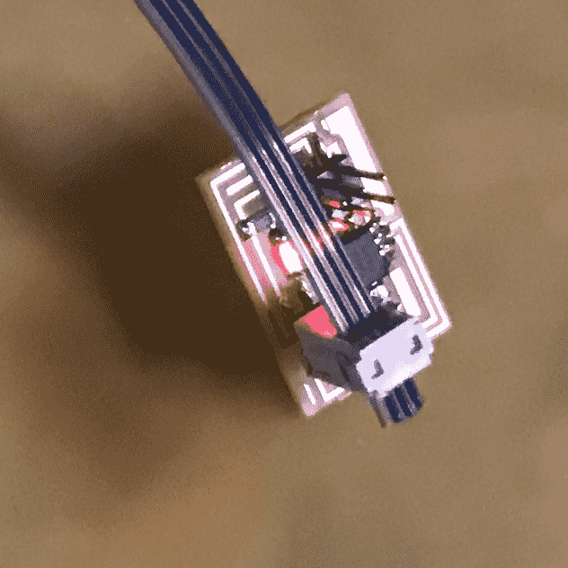
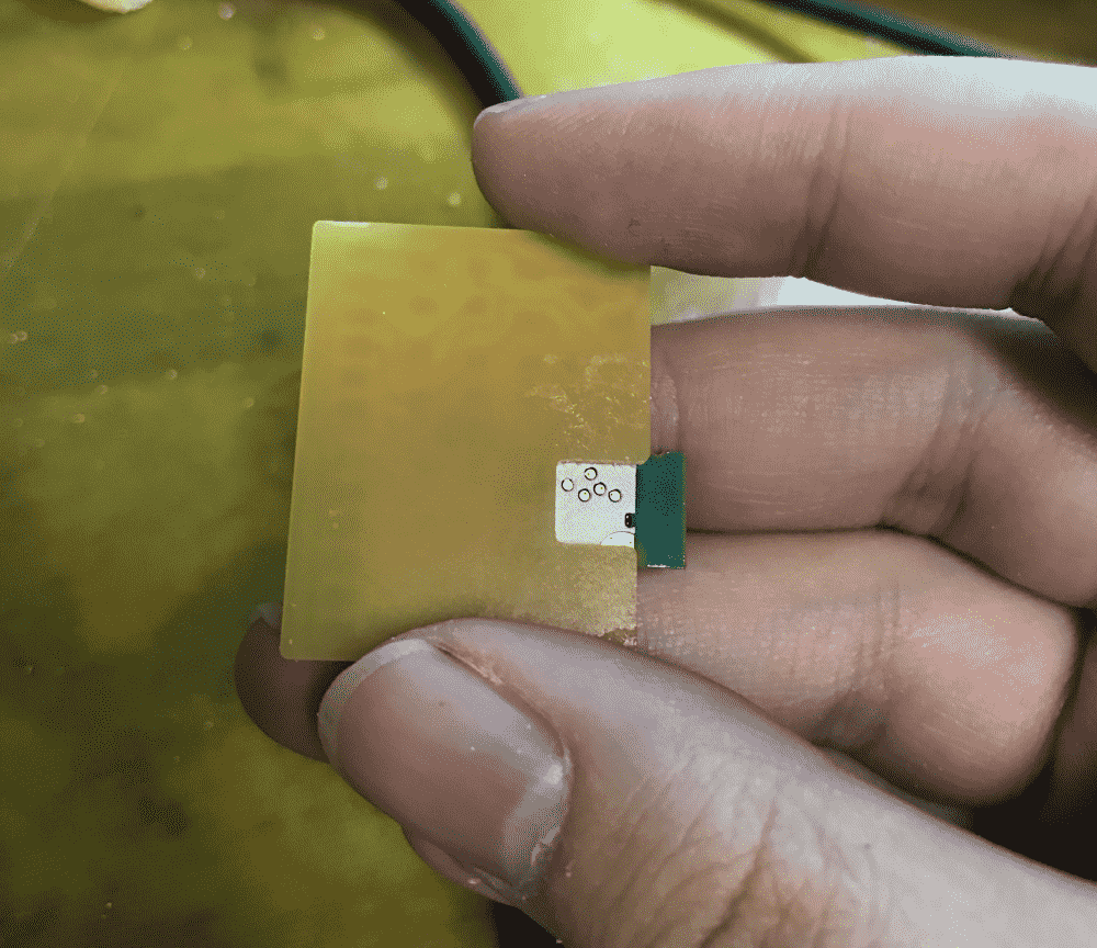
I quickly milled the board. The RN4871 doesn't have “pins”, they have small dents where the pins should have been. But that didn't turn out to be much of an issue for soldering.
I also cut my board's outline so that there's nothing behind the RN4871, as warned by the footprint “KEEP-OUT ZONE”.
When I connected the module to my SAMD21E breakout, which was plugged into my laptop, the two indicator LED's came to life.
However, the next day, when I sat down and tried to program the boards, I wasn't able to communicate with RN4871 from SAMD21E. After a long period of fiddling around with the code, I realized that I might have the TX/RX inverted.
So the labels “RX” and “TX” on RN4871's footprint doesn't mean that “you should connect your RX/TX here”, in fact they mean “I am RX/TX, connect your TX/RX to me”.
In retrospect, the latter reading makes more sense, yet somehow, I was quite convinced of the former when I designed the board.
I was chilling at home on a Saturday morning, doing some relaxing bluetooth stuff, but now I needed to go to school to fix it. And the subway was under construction…
Anyways some two hours later I was finally at the shop testing my hypothesis with a bunch of jumper wires.
I was able to receive the %REBOOT% message from the RN4871, when I short the reset pin to ground, but the communication was unfortunately one-sided. I tried telling it $$$ and + and R,1 etc. as the datasheet suggested, but RN4871 simply ignored me.
So I started searching the internet, and discovered that, despite the datasheet saying “all commands end with \r (cartridge return)” and “RN4871 will respond to anything ending with \r”, the very first command you need to send it, the $$$, doesn't count as a “command”, and so can NOT end with a “\r”. What???
So I sent the $$$ without a \r. It worked! Now I could tell the module to report various status, and change its name so I could more easily find it with another device. I decided to name it LDsRN4871, meaning “Lingdong's RN4871”.
Now that the serial is working, I needed to get rid of the jumper wires, and permanently fix my circuit.
The TX and RX lines are next to each other. I first broke both of them with a blade. Then I used solder to make a diagonal connection. Finally I soldered a diagonal 0-ohm resistor on top to make the other connection. I checked with a multimeter that the connections were good. Couldn't believe that my hack worked!
Talking to the bluetooth via phone
I downloaded an Android app called “BLE Scanner”, because it seemed to be what people were using. In it, I can find my RN4871, and write to a value of a “characteristic”. Apparently, writing “values” to a “characteristic” means sending data in BLE land. I hope they find a shorter name than “characteristic” next time, it's so hard to spell when I code.
In the video below (same as the one at the beginning of the post, reproduced here for convenience), you can see how I used a phone to talk to the RN4871 via bluetooth, which talks to a SAMD21E microcontroller, which controls a servo and also pass on the command to a SAMD11D microcontroller via serial, which controls a OLED display via I2C.
Writing a bluetooth app
The BLE Scanner GUI is usable: it's not a super great UX, but I've seen much worse. However, I thought it'd be nice if I make my custom GUI.
I found out that there's a Web Bluetooth API, supported on Chromes and Androids. Great, I can slap together some JavaScript to talk to my board.
It ended up more complicated than I thought, and because the Android browser's buffer for BLE is so small, I couldn't send more than a couple bytes. So in the end, I made my demo in Chrome on my MacBook:
You can find the source code here and online demo here. Of course, you would also need to fabricate my bluetooth boards to make it work (or modify the codes so that they work for your setup).
The magic one-liner that actually does the communication is reproduced below:
let namePrefix = "LDsRN4871";
let serviceUUID = '49535343-fe7d-4ae5-8fa9-9fafd205e455';
let characteristicUUID = '49535343-1e4d-4bd9-ba61-23c647249616';

navigator.bluetooth.requestDevice({filters:[{namePrefix}],optionalServices:[serviceUUID]}).then(device=>{console.log(device.name);return device.gatt.connect()}).then(server=>server.getPrimaryService(serviceUUID)).then(service=>service.getCharacteristic(characteristicUUID)).then(characteristic=>characteristic.writeValue(new TextEncoder().encode("hello"))).catch(error=>{console.error(error);})
I also tried writing a native android app, using Processing Android mode. I progressed as far as scanning, finding and connecting to my bluetooth module, starting the “gatt server”, activating the “service”, finding the “characteristics”, but when I actually wrote some values to the characteristic, the RN4871 didn't seem to receive them. The android app was somehow falsely convinced that the bytes were written. I gave up.
You can find my half-baked code below. Maybe if you're smarter than me, you can figure out how to make it work:
import android.content.Intent;
import android.bluetooth.BluetoothAdapter;
import android.bluetooth.BluetoothDevice;
import android.bluetooth.BluetoothManager;
import android.bluetooth.BluetoothSocket;
import android.bluetooth.BluetoothGattCharacteristic;
import android.bluetooth.BluetoothGattCallback;
import android.bluetooth.BluetoothGatt;
import android.bluetooth.BluetoothGattService;
import android.bluetooth.BluetoothProfile;
import android.bluetooth.BluetoothGattDescriptor;
import android.bluetooth.le.BluetoothLeScanner;
import android.bluetooth.le.ScanCallback;
import android.bluetooth.le.ScanResult;
import android.content.Context;
import android.os.Handler;
import android.Manifest;
import android.content.pm.PackageManager;
import java.util.Set;
import java.util.List;
import java.util.UUID;

String namePrefix = "LDsRN4871";
String serviceUUID = "49535343-fe7d-4ae5-8fa9-9fafd205e455";
String characteristicUUID = "49535343-1e4d-4bd9-ba61-23c647249616";

BluetoothAdapter adapter;

BluetoothLeScanner scanner;

boolean scanning = false;
Handler handler = new Handler();

// Stops scanning after 10 seconds.
static final long SCAN_PERIOD = 10000;


private final BluetoothGattCallback gattCallback = new BluetoothGattCallback() {
    @Override
    public void onConnectionStateChange(BluetoothGatt gatt, int status, int newState) {
        if (newState == BluetoothProfile.STATE_CONNECTED) {
            println("successfully connected to the GATT Server");
            gatt.discoverServices();


        } else if (newState == BluetoothProfile.STATE_DISCONNECTED) {
            println("disconnected from the GATT Server");
        }
    }
    @Override
    public void onServicesDiscovered (BluetoothGatt gatt, int status){

        println(gatt.getServices());

        BluetoothGattService service = gatt.getService(UUID.fromString(serviceUUID));

        println(service);

        //println(service.getCharacteristics());

        List<BluetoothGattCharacteristic> characteristics = service.getCharacteristics();

        for (int i = 0; i < characteristics.size(); i++){
          println(characteristics.get(i).getUuid());
        }

        BluetoothGattCharacteristic characteristic = service.getCharacteristic(UUID.fromString(characteristicUUID));


        gatt.setCharacteristicNotification(characteristic, true);
        UUID uuid = UUID.fromString("00002902-0000-1000-8000-00805f9b34fb");
        BluetoothGattDescriptor descriptor = characteristic.getDescriptor(uuid);
        descriptor.setValue(BluetoothGattDescriptor.ENABLE_NOTIFICATION_VALUE);
        gatt.writeDescriptor(descriptor);

        println(characteristic);

        for (int i = 0; i < 1000; i++){
          println(characteristic.setValue("(l1)"));
          try
{
    Thread.sleep(100);
}
catch(InterruptedException ex)
{
    Thread.currentThread().interrupt();
}
        }
        println(characteristic.getValue());
    }
};

ScanCallback leScanCallback =
  new ScanCallback() {
      @Override
      public void onScanResult(int callbackType, ScanResult result) {
          //println("found");
          super.onScanResult(callbackType, result);
          BluetoothDevice device = result.getDevice();
          String name = device.getName();
          if (name != null && name.startsWith(namePrefix)){
            println(name);
            println(device);
            device.connectGatt(getContext(), false, gattCallback);
            scanner.stopScan(leScanCallback);
          }
      }
  };

private void scanLeDevice() {
    if (!scanning) {
        // Stops scanning after a predefined scan period.
        handler.postDelayed(new Runnable() {
            @Override
            public void run() {
              if (scanning){
                println("timeout");
                scanning = false;
                scanner.stopScan(leScanCallback);
              }
            }
        }, SCAN_PERIOD);
        println("scanning");
        scanning = true;
        scanner.startScan(leScanCallback);
    } else {
        scanning = false;
        scanner.stopScan(leScanCallback);
    }
}

void setup(){
  adapter = BluetoothAdapter.getDefaultAdapter();

  String[] permissions = {Manifest.permission.ACCESS_FINE_LOCATION};
  getActivity().requestPermissions(permissions, 2);

  getActivity().startActivityForResult(new Intent(BluetoothAdapter.ACTION_REQUEST_ENABLE),1);

  scanner = adapter.getBluetoothLeScanner();
  scanLeDevice();
}

void draw() {
}
Downloads
My design files (KiCAD) can be downloaded below:
- SAMD11D semi-breakout serial board schematics
- SAMD11D semi-breakout serial board layout
- Serial module for SAMD21E breakout schematics
- Serial module for SAMD21E breakout layout
- Bluetooth (RN4871) for SAMD21E breakout schematics
- Bluetooth (RN4871) for SAMD21E breakout layout
My programs (.ino) can be downloaded below: